AEVITA: Designing Biomimetic Vehicle-to-Pedestrian Communication
Protocols for Autonomously Operating & Parking On-Road Electric Vehicles
by
Nicholas Pennycooke
B.Sc.
ME, MIT (2010)Submitted to the Program in Media Arts and Sciences, School of Architecture and Planning,
in partial fulfillment of the requirements of the degree of
Master of Science in Media Arts and Sciences
~ A> ~
at the
Massachusetts Institute of Technology
September 2012©
2012 Massachusetts Institute of Technology. All rights reserved.Author:
P gram in Media Arts and Sciences, MIT September, 2012
Certified by:
Kent Larson Principal Research Scientist, MIT Media Lab Thesis Supervisor
:1
Accepted by:
Prof. Patricia Maes Associate Academic Head, Program in Media Arts and Sciences
AEVITA: Designing Biomimetic Vehicle-to-Pedestrian Communication
Protocols for Autonomously Operating & Parking On-Road Electric Vehicles
by
Nicholas Pennycooke B.Sc. ME, MIT (2010)
Submitted to the Program in Media Arts and Sciences, School of Architecture and Planning, on August 7, 2012 in partial fulfillment of the requirements of the degree of
Master of Science in Media Arts and Sciences at the Massachusetts Institute of Technology
September 2012
Abstract
With research institutions from various private, government and academic sectors performing research into autonomous vehicle deployment strategies, the way we think about vehicles must adapt. But what happens when the driver, the main conduit of information transaction between the vehicle and its surroundings, is removed?
The EVITA system aims to fill this communication void by giving the autonomous vehicle the means to sense others around it, and react to various stimuli in as intuitive ways as possible by taking design cues from the living world. The system is comprised of various types of sensors (computer vision, UWB beacon tracking, sonar) and actuators (light, sound, mechanical) in order to express recognition of others, announcement of intentions, and portraying the vehicle's general state. All systems are built on the 2 nd version of the 1/2 -scale CityCar concept vehicle,
featuring advanced mixed-materials (CFRP + Aluminum) and a significantly more modularized architecture.
Thesis Supervisor: Kent Larson
AEVITA: Designing Biomimetic Vehicle-to-Pedestrian Communication Protocols for Autonomously Operating & Parking On-Road Electric Vehicles
by
Nicholas Pennycooke
Thesis Reader:
Alex 'Sandy' Pentland Professor MIT Media Arts and Sciences
4\ ~
T
4Li
T
AEVITA: Designing Biomimetic Vehicle-to-Pedestrian Communication
Protocols for Autonomously Operating & Parking On-Road Electric Vehicles
by
Nicholas Pennycooke
Thesis Reader:
Emilio Frazzoli Associate Professor MIT Laboratory for Information and Decision Systems
457
0-011,
I
-1
1~
0
-Vt
AL LA LIFT
ilk
NI ~
£ ~4;
AI
LAcknowledgements
I would like to take a moment to acknowledge the many incredible people who have worked with me on this immense project over the last few years. First, I would like to thank Kent for taking up the helm at a crucial time for our research group, and believing in
my work and my vision. His kindness, hospitality, and guidance kept me on track while I swam through these uncertain waters.
Thank you to my readers, Assoc. Prof. Emilio Frazzoli and Prof. Sandy Pentland for their help in polishing this document into an acceptable academic account, as well as a future technology-inspiring story.
I would not be in a position to be writing this thesis if not for my colleague and friend Will Lark Jr. I started out working for him as a clueless undergraduate, but with his support and inspiration I am where I am today. Praveen Subramani, my partner in both academia and social exploits, for always being a good ear, great speaker, and grand person. To all my dear friends for helping me maintain that healthy work/life balance. Also, many thanks to my family, especially my parents, for always being my biggest fans.
If not for my extremely talented team of undergraduates over the past 2 years, I would be
still in the machine shop for possibly another 2 years:
Sean Cockey Laura Shumaker Chad Bean
Katharine Daly Katarina Struckmann Daniel Goodman
Aron Dreyfoos Princess Len M Carlos Michael Buchman
Tom Lutz and John DiFrancisco, shop managers, for maintaining the amazing tools in the workshop, providing excellent advice on the best ways to make awesome things, and generally making sure I keep all my limbs intact.
I would also like to thank the entire Denokinn and Hiriko teams, especially Carlos, for providing not only the funding to make REVITA a reality, but also in believing in our dream of making the CityCar concept a reality.
Last, but by no means, the least, the late Professor William J. Mitchell.
Bill, Praveen and I were the last of your admitted students. The last SoBs. I can only hope that the work that we have
completed fits into your wonderful vision of how the world needs to adapt to all these new challenges we face everyday.
It's been almost 2 years to the day since you left, and I will
never forget the amazing opportunity you granted me, believing that I truly had something to offer to that vision. I cannot possibly begin to thank you enough. This is for you. It's important to get the technology and the policy right, but in the end, the way you break a logjam is by engaging people's imagination, people's desire, by creating things that
they never thought of before.
itt1GE
s
Table of Contents
[1.0] Introduction ... 16
[1.1] The State Of Today's Cities... 16
[1.2] The State Of Today's Transportation... 17
[1.3] Changing M obility...18
[1.4] The CityCar...20
[1.5] Introducing Autonom y... 22
[1.5.1] The Expanded Gradient Of Autonom y ... 25
[1.6] Introducing R VITA ... 27
[2.0] Related W ork ... 29
[2.1] Purpose Built Autonomous Vehicle Deployment... 29
[2.2] Biom im etic and H M I Research... 32
[3.0] 2nd Generation City Car System Development ... 35
[3.1] Predecessors ... 35
[3.1.1] Hiriko...37
[3.2] 2nd Generation % Scale Platform Design Overview... 38
[3.3] M ain Structural Fram e ... 41
[3.4] Pow ertrain M odule ... 45
[3.5] Folding Linkages ... 54
[3.5.1] Prim ary Linkages ... 56
[3.5.2] Folding Actuators...57
[3.5.3] Secondary And Synchro Link... 59
[3.6] Robot W heel M odule ... 61
[3.6.1] Arm And Suspension ... 62
[3.6.2] Steering...64
[3.6.3] Steering Control...66
[3.6.4] Drive...69
[3.6.5] Drive Control...72
[3.6.6] W heel And Tire ... 75
[4.0] EV ITA System D evelopm ent ... 78
[4.1] D esign Overview ... 78
[4.2] Recognition Subsystem ... 81
[4.2.1] Com puter Vision: Kinect Integration... 81
[4.2.2] Eye Assem blies...84
[4.3] Announcem ent System ... 91
[4.4] Body Language System ... 94
[4.4.1] Basic Subsystem ... 94
[4.4.2] Vehicle Login and Personalization ... 97
[4.4.3] Com bined Subsystem Behaviors... 99
[4.5] W ireless Controller...102
[4.6] A VITA Sum m ary ... 103
[5.0] Technical Evaluation ... 104
[5.1] 2GH S Platform & Control...104
[5.1.1] Folding M echanism Failure M ode...104
[5.1.2] Folding M echanism Loading & Speed ... 105
[5.1.4] Throttle Input Testing...107
[5.2] Recognition ... 109
[5.2.1] Kinect Sensor Feasibility...109
[5.2.3] Kinect Tracking Program Selection...110
[5.2.4] AETP Hum an Identification...111
[5.2.5] Eye Assem bly Tracking Speed...113
[5.2.6] Continuous Eye Tracking Perceptions...114
[5.3] Announcem ent... 115
[5.3.1] Non-directional speakers ... 115
[5.4] Body Language...116
[5.4.1] RAW L Light Blending ... 116
[5.4.2] RAW L Reaction Tim e...116
[5.4.3] Com bined Body Language System Perform ance...117
[5.5] System -w ide Perform ance...118
[6.0] Conclusion ... 119
[6.1] Findings...119
[6.2] Im plications and Im plem entation ... 120
[7.0] Future W ork ... 122
[7.1] User Evaluation ... 122
[7.2] Gestural Commands and Pedestrian-to Vehicle Communication...122
[7.3] Development of a Communication Standard...123
[7.4] Possible Applications Today... 123
[7.5] Integration of Good Driver Habits...124
[8.0] Bibliography...125
[9.0] A ppendix...128
[9-A] User Study...128
Instructions to The Participant...128
Instructions to The Conductor...129
Interaction M odes...131
Questionnaire ... 133
[9-B] Vehicle Personalization via NFC Devices ... 135
[9-C] Geometric Steering Angle -Servo Relationship ... 137
[9-D] 10 Box Pin Schem atics ... 138
[9-E] Castle M am ba M ax Pro ESC Settings... 1 39 [9-F] Additional Design Im ages... 140
[9-G] ATP C# Code ... 145
M ainW indow .xam l ... 145
M ainW indow .xam l.cs...146
[9-H] Arduino Code...161
Prim ary Front M icro...161
Prim ary Rear M icro ... 173
Pupil M icro...176
[9-I] Custom /M odified Arduino Libraries ... 179
BLINKM _FUNCS_12C.h ... 179
ELESCUDO.h ... 182
List of Figures & Tables
Figure 1-1: 2010 C02 Emissions from Fossil Fuel Combustion 17
Figure 1-2: Selection of implemented shared mobility system providers 18
Figure 1-3: Reinventing the Automobile cover 19
Figure 1-4: The MIT Media Lab CityCar. Image by W. Lark 20 Figure 1-5: The MIT Media Lab CityCar's maneuverability enabled by its robot wheels. Image by W. Lark
21 Figure 1-6: Parking ratio enabled by the CityCar folding structure 21 Figure 1-7: Changing parking density afforded by autonomy and the CityCar 22 Figure 1-8: Some of the key stakeholders in autonomous vehicle research 23
Figure 1-9: The basic gradient of autonomy 24 Figure 1-10: Definition of vehicle automation, as recommended by BASt 24 Figure 1-11: The expanded gradient of autonomy 26
Figure 1-12: The application space of the EVITA system 28
Figure 2-1: The GM EN-V 29
Figure 2-2: Personal Robotics Group's Aida 32
Figure 3-1: 1st half-scale CityCar prototype 35
Figure 3-2: CAD - 1st generation half-scale CityCar prototype 36
Figure 3-3: The Hiriko Fold, commercialization of the concept CityCar 37
Figure 3-4: CAD -The 2nd generation M scale CityCar platform with EVITA, unfolded 38
Figure 3-5: CAD -The 2GHS platform with AVITA, folded 39
Figure 3-6: CAD -The 2GHS main structuralframe 41 Figure 3-7: CAD -The 2GHS main structuraliframe, as viewed from below 43 Figure 3-8: The 2GHS platform, with both underbody CFRP pieces top center 44 Figure 3-9: CAD -The 2GHS platform, with the top CFRP attached 44
Figure 3-10: CAD -The 2GHSpowertrain module, with some robot wheel components attached 45
Figure 3-11: The dry 2GHS powertrain module with tray 46 Figure 3-12: CAD -The 2GHS powertrain module, with some robot wheel components attached, as
viewed from top 47
Figure 3-13: CAD -The 2GHS platform showing structural difference between front and rear powertrain
modules, as viewed from below 48
Figure 3-14: The lead/trail arm attached to the powertrain module, showing the angular offset 49 Figure 3-15: 3D printed ABS plastic suspension upper connection point 50 Figure 3-16: FEA optimized 6061-T6 suspension upper connection point 50
Figure 3-17: Powertrain module with tray pulled out on drawer slides 51
Figure 3-18: Internals of thefront powertrain module's tray. At right, 10 Box 52
Figure 3-19: The completed rear powertrain module's tray 53
Figure 3-20: CAD -The 2GHSfolding linkage main elements 54 Figure 3-21: CAD -The 2GHS primary linkage 56
Figure 3-22: The Linak LA23 actuator, extended 58
Figure 3-24: The Linak LA23 actuator, retracted 58
Figure 3-25: The secondary and synchro links 59
Figure 3-26: CAD -The 2GHS folding sequence, showing the lift of the main structural frame, and the overlap of thefront and rear powertrain pivot points 60
Figure 3-27: CAD -The 2GHS front-left/rear-right robot wheel module, without suspension 61
Figure 3-28: The 2GHS front-left/rear-right arm and suspension structure 62
Figure 3-29: The 2GHS robot wheel steering mechanism 64 Figure 3-30: CAD -Details of the robot wheel architecture and the steering mechanism 65
Figure 3-31: Diagrammatic representation of the Ackermann steering geometry 67
Figure 3-32: The 2GHS robot wheel drive motor and motor mount 69
Figure 3-33: The 2GHS robot wheel hub assemblies, without lug bolts or bearings 70
Figure 3-34: The 2GHS robot wheel hub assembly, mounted to the drive/steer assembly 71
Figure 3-36: CAD - The 2GHS rim and tire 75
Figure 3-37: The two parts of the 2GHS wheel, before epoxying 76
Figure 3-38: The 2GHS rim and tire mounted to the hubs 76
Figure 3-39: EVITA, the complete platform 77
Figure 4-1: EVITA system data/signal network 78
Figure 4-2: Arduino Uno and Mega 2560 microcontroller boards 79
Figure 4-3: Microsoft Kinect sensor mounted on EVITA 81
Figure 4-4: Microsoft Kinect 82
Figure 4-5: EVI TA's human and skeleton tracking, early version of the ETP 83
Figure 4-6: EVI TA's left eye 84
Figure 4-7: Sparkfun original El Escudo Arduino shield 85
Figure 4-8: EVITA's pan and tilt servos, right eye, without pupils 87
Figure 4-9: Difference in angle neededfor two rotating elements to converge on a single point 88
Figure 4-1 0:EVI TA's eyes and Kinect sensor, ETP running on screen in background 90
Figure 4-11: CAD - EVI TA's announcement system 91
Figure 4-12: EVI TA's announcement system 92
Figure 4-13: Parallax Ping! sonar sensor 94
Figure 4-14: One group of RAWLs, attached to the stationary motor mount 96
Figure 4-15: Diffused and reflected light responding to changes in object proximity 96
Figure 4-16: EVI TA RFID login reader and cards 97
Figure 4-17: IEVI TA login RAWL personalization 98
Figure 4-18: EVITA aggression sequence 100
Figure 4-19: EVITA submission sequence 101
Figure 4-20: Microsoft Xbox 360 Wireless Controller for Windows (Microsoftcom) 102 Figure 5-1: Rear 4-bar linkage and front 4-bar linkage droop 106
Figure 5-2: Scaled forward and reverse throttle example 108
Figure 5-3: Original tracking program based on depth thresholds 110
Figure 5-4: Example 1 of The Infamous Small Man 111
Figure 5-5: Example 2 of The Infamous Small Man 112
Figure 5-6: Diagnostic print out via serial monitor of primary front micro 114
Table 4-1: Summary of two examples of body language system combinations 99
Table 5-1: Folding actuator loading and speeds 105 Table 5-2: Calibration data from ESC setting printout 107
[i.o] Introduction
[1.1] The State Of Today's Cities
Today's cities are experiencing rapid urban densification, the likes of which has never been before seen in human history. For the first time in 2007-2008, the United Nations Population Division estimates that more than half of the world's population now lives in cities'. This trend is expected to continue, with over 90% of expected population growth to occur in these urban cells. With this growth comes the opportunity to reduce suburban sprawl, integrate more mixed-use zoning, and increase the efficiency at which the city operates from both an energy and
transportation point of view. More dense urban environments create a sense of vibrancy, as its inhabitants interact in ways suburban sprawls cannot achieve. However, today's cities were not built with this rapid growth in mind. In fact, the exact opposite is occurring. According to the United Nations Department of Economic and Social Affairs, Population Division, there is a trend of decreasing density. If current rates remain, the average land occupied by cities with
populations of over 100,000 inhabitants will increase by a factor of 2.75 by 20302.
Current infrastructure in most modern cities is already struggling to keep up with the demand being asked of it. The American electric grid is largely made up of components built decades ago. Energy supply does not match demand, and so there are frequently megawatts of electricity being produced for non-existent loads. Similarly, spikes in electricity demand puts massive strain on the grid, requiring supplemental sources offering little to no resiliency or redundancy should portions fail.
1 United Nations, Department of Economic and Social Affairs, Population Division. (2011). World Population Prospects: The 2010 Revision. New York
2 United Nations, Department of Economic and Social Affairs, Population Division. (2011). Population
[1.2]
The State Of Today's Transportation
Transportation systems are similarly at peril. There exists an excess of personally owned automobiles, causing traffic congestion in most major metro areas, and represents a large portion of total C02 and other greenhouse gas emissions per year. The US Environmental Protection Agency (USEPA) 2012 Greenhouse Gas Inventory states, "The transportation end-use sector accounted for 1,772.5 Tg C02
Eq. in 2010, which represented 33 percent of C02 emissions, 23 percent of CH4
emissions, and 48 percent of N20 emissions from fossil fuel combustion, respectively." Further, it states that of that figure, passenger vehicles and light-duty trucks accounted for 61% of total transportation related emissions3. If a non-incremental modal shift in how we think about mobility does not occur, the veins and arteries of the city, supplying its lifeblood - the people - will be constantly congested.
z5W
PAW"~ CWdoxn2X2 0E0m Fgr 1-1 21 CO2 1,74S
500 22430
42
Figure 1-1: 2010 C02 Emissions from Fossil Fuel Combusfion4
In order to support the growth we can expect to see, cities will have to move away from traditional, private ownership-centric transportation models, integrating a mobility ecosystem that is designed specifically around the needs of its
3 USEPA. (April 2012). Inventory of U.S Greenhouse gas emissions and sinks: 1990-2010, p3-13 4 USEPA. (April 2012). Inventory of U.S Greenhouse gas emissions and sinks: 1990-2010, Figure 3-5
inhabitants. In the last decade, there has been a notable boom in small to medium scale rollouts of such systems, providing some evidence that there are individuals
and municipalities considering the implications of integrating shared mobility.
[1-3]
Changing Mobility
outolib'
!rHubway
Figure i-2: Selection of implemented shared mobility system providers
One such system is Mobility on Demand (MoD). Originally conceptualized by the Smart Cities research group within the MIT Media Lab under Professor William J. Mitchell (1944-2010). MoD is a one-way, shared use mobility system which seeks to better balance the mobility supply and demand ratio, all the while integrating
sustainable vehicle technology, distributed information and renewable energy systems, and minimizing the urban footprint required to move people from A to B. Vehicles can be picked up or rented from a nearby MoD station, and driven to the
user's destination, parking it any other non-full station with no responsibility or even expectation for the vehicle to returned to its original pickup point. Outlined in
further detail in Reinventing the Automobile: Personal Urban Mobility for the 2 1st
Century (2010), MoD combines many of the best features of currently deployed shared mobility systems, some of which as presented in Figure 1-2.
Figure 1-3: Reinventing the Automobile cover
Some of the key features of MoD include its one-way sharing, dynamic pricing incentive-based vehicle redistribution, and constant information sharing across the system. Perhaps most interestingly, however, are the types of vehicles used in MoD. Other one-way systems such as Autolib' and Hubway utilize only one kind of vehicle throughout: cars and bicycles, respectively. MoD seeks to improve upon this by providing a mobility ecosystem of connected electric vehicles of various types and form factors, allowing users to take the right kind of vehicle for the type of trip they intend to take. By providing a fleet of electric assist bicycles and
tricycles, scooters and lightweight passenger vehicles, MoD is able to provide clean, efficient mobility satisfying the lion's share of most urban trips.
[1.4] The CityCar
Figure 1-4: The MIT Media Lab CityCar. Image by W. Lark.
Of these vehicles, the concept CityCar not only solves many of the mobility issues
MoD attempts to tackle, but also sets a far reaching precedent for the future of mobility. The CityCar is a lightweight, two passenger electric vehicle, built on a
highly modular platform, giving it a feature set that directly complements and
enhances MoD's effectiveness. Central to the CityCar's architecture are the Robot Wheels at its corners. The core principle of Robot Wheel technology, as defined by Raul Poblano5, is the consolidation of a vehicle's complexity into its wheels, thus freeing the rest of the chassis from its typically static construction. Each corner contains its own drive motor, steering actuator, braking, and suspension systems, has no direct mechanical link between units, and is independently controllable through drive-by-wire technology. Each wheel has a total sweep of approximately 8o degrees, allowing for high maneuverability, including the ability to spin around its own central axis, dubbed an'O-Turn'.
5 Poblano, R V. (2008). Exploration of robotic-wheel technology for enhanced urban mobility and city scale omni-directional personal transportation. M.S. Thesis. Massachusetts Institute of Technology, USA.
Figure 1-5: The MIT Media Lab CityCar's maneuverability enabled by its robot wheels. Image by W. Lark.
By removing the traditional drivetrain, the chassis can be much more dynamic: the
vehicle can be made to fold. By enabling folding, the CityCar can reduce its total footprint to take up less than 1/3 of the space of a normal car. Coupled with the front ingress and egress, three of these vehicles can fit in one 8' by 18' parking spot.
a?-rpO fnw* 4-1 (1500 MV4 CtyCar (unfodc CityCw olded
Folde Cfty~w v& conventlon 4-doo sedan
Parldng ratio- 3.3: 1
Figure 1-6: Parking ratio enabled by the CityCar folding structure6
This complements MoD by increasing the utilization rate of the land, and reducing the total urban footprint required of the mobility system as a whole. Introducing dynamic incentives for redistribution of the MoD fleet is a solution viable with technology available today. This requires relying on human behavioral dynamics, which at best is sporadic. Other vehicle sharing programs rely on the much more
difficult, inefficient and expensive method of manually moving vehicles to the stations where they are needed.
[1.5]
Introducing Autonomy
ga, lo
Figure 1-7: Changing parking density afforded by autonomy and the CityCar
What then, if we enabled this system to redistribute itself on demand, utilizing vehicles that redistribute themselves. Further, if we remove the need for human ingress, we can pack these vehicles even tighter, up to a ratio of 7 vehicles to the space required to park and move one regular sedan. The CityCar is more of an electronic car, than simply electric. It is already controlled by on board computer systems in a way not found in today's available vehicles. This makes it a
particularly viable platform to deploy autonomous vehicle technology, as it only requires the addition of the various sensors needed to enable autonomy.
Mercedes-Benz
A:TOYOTA
£ State Farm
VEHCOATEIN RUNANIND
VEHICLE SYSTEMS INTEPNATIONAL
Figure 1-8: Some of the key stakeholders in autonomous vehicle research
Searching for the terms "autonomous car", or "cars that drive themselves" gives a very quick glimpse into the ever-expanding world of autonomous vehicle research. Parallel parking assists, which perform the sometimes tricky maneuver
automatically for the driver, have been installed in vehicles as early as 2003;
Toyota being the first to deploy a commercially viable solution on that model year's Prius sedan7. Those shopping for new high-end luxury automobiles such as the
2012 Lexus LS are afforded a vehicle that has advanced pre-collision detection
systems, and 'Lane Keep Assist'that uses radar to keep the vehicle driving down the middle of its current lane8. The DARPA urban challenge, which blends the
interests of the US Department of Defense and those of academia, answers "[ ...] a congressional mandate [ ...] to develop autonomous vehicles that reduce or even eliminate the presence of conductors in order to limit the loss of life on land military operations."9 Private corporations such as Google have already logged over 100,000 miles of driving with little to no human intervention.10
7 Time. (2003). Best Inventions of 2003. Retrieved October 25, 2011, from Time Magazine:
http://www.time.com/time/specials/packages/article/o,28804,1935038_1935083_1935719,oo.html 8 Lexus. (2011). LS Safety & Security. Retrieved October 25, 2011, from Lexus:
driver
vehicle
full control
full control
Figure 1-9: The basic gradient of autonomy
What this exposes is that autonomous vehicle research is actively occurring on a spectrum. In fact, one of the key tasks of the majority of the stakeholders in autonomous vehicle technology is to ratify a legally robust definition set of the various levels of autonomy, examples of which are used above in Figure 1-8. Currently, one of the accepted starting points towards this goal is the BASt definition set, presented below."
Definition of vehicle automation-degrees:
*Driver Only: Human driver executes manual driving task c- *Driver Assistance: The driver permanently controls
either longitudinal or lateral control. The other task can be automated to a certain extent by the assistance system. ePartial automation: The system takes over longitudinal
and lateral control, the driver shall permanently monitor the system and shall be prepared to take over control at any time.
* High automation: The system takes over longitudinal and lateral control; the driver must no longer permanently monitor the system. In case of a take-over request, the
12 driver must take-over control with a certain time buffer.
* Full automation: The system takes over longitudinal and lateral control completely and permanently. In case of a take-over request that is not carried out, the system will return to the minimal risk condition by itself.
Tom M. Gasser 26t Oct. 2011 slide No. 12
Figure 1-1o: Definition of vehicle automation, as recommended by BASt
10 Markoff, J. (2010, October 9). Smarter Than you Think. Retrieved October 25,2011, from The New York
Times: http://www.nytimes.com/2lo/o/o/science/logoogle.html
11 Gasser, T. M. (October 26, 2011), Additional Requirements for Automation Liability and Legal Aspects
[1-5.1] The Expanded Gradient Of Autonomy
The world of 'Google' vehicles may be some years away though, as both technology and policy are not yet ready. The state of Nevada recently became the maverick on the policy front, however, by becoming the first municipality to sign into law, provisions that will set the precedent for autonomous vehicles to operate on their highways12. Once the technology becomes commoditized to the point of mass
deployment, as the stakeholders in Figure 1-7 are working towards, there are several new use cases for self-driving vehicles - also occurring on its own gradient.
As a nascent technology, which involves relinquishing human trust to a mechanical system, autonomous vehicle technology will not immediately be the Google car. Figure 1-10 not only shows how autonomy not only progresses from driver to
vehicle control, but also that two versions of autonomy exists - with and without a driver. Autonomy may begin simply as controlled, indoor operation such as in a confined parking structure. This 'robotic valet' involves a system where the complex sensor arrays and computing requirements are moved from the vehicle into parking lot infrastructures, allowing drivers to have their vehicles park themselves into ultra-efficient arrays. At the far end of the spectrum are vehicles whose driver algorithms are fine-tuned to the function the vehicle will be
performing. Using biometric data and driving behavior extracted by analyzing the habits of good taxi drivers, good truck drivers, autonomous vehicles can behave as if they are expert drivers of their designated jobs. It could be taken further, such that an autonomous vehicle operating in a sleepy southern town will be a lot more polite, than say one tasked to navigate the hectic streets of Manhattan.
12
Shunk, C. (2011, June 12). Nevada passes law governing the use of autonomous vehicles. Retrieved October
25, 2011, from Autoblog:
41P
driver
vehicle
full control
W
M
JW
full control
cornwoWd=o
restriced sOw-speed-outdoo opeatio
o=ptdo
ful-seed opera*o with d&W"e profe
autonomy autonomy without driver with driver Figure 1-11: The expanded gradient of autonomy
Most use cases of autonomy currently assume that there will always be a driver in the seat, being shuttled from A to B with minimal input from the vehicle's
passengers. Platooning, dynamic self-redistribution, on-demand pickup, and fixed-circuit autonomous shuttles are all applications where there is no driver while the vehicle navigates the environment. Normally, when on-road vehicles are operating, the feedback loop always occurs through the driver or passenger(s): eye contact, horns, turn signals, shouting, and hand gestures. These communication
conventions are largely taken for granted, and happen in a very fast, natural way. This can be easily realized by observing a busy intersection.
But if an autonomous system such as the one described above was to proliferate, how do we go about handling these intuitive conventions once we remove the human factor? Statistics from NHTSA show that in 2009, there were 4092
pedestrian fatalities caused by accidents with motor vehicles.13 This accounted for
1 3
National Highway Traffic Safety Administration. (2012), Fatality Analysis Reporting System (Fars) Encyclopedia. Retrieved June,28, 2012, from NHTSA:
12% of all vehicular fatalities that year. It is not difficult to imagine that most of these incidents were likely because of miscommunication, or reduced
pedestrian/driver vigilance. This situation gives us the unique opportunity to not only match, but also exceed the currently low levels of communication quality between vehicles and pedestrians, regardless of whether or not a human is in the driver seat.
[1.6] Introducing IEVITA
The purpose of this thesis is to provide various answers to this problem space, by breaking the question down into its constituents, and proposing viable
electromechanical interventions that address each concern. As a pedestrian, one has to be able to know what the autonomous vehicle is about to do next. The vehicle has to be able to communicate recognition of those around it, and
subsequently announce its intentions. These communication protocols have to be achieved immediately, and intuitively, so as to not require the populous to read an instruction manual prior to feeling safe. Such a system will be most powerful when it can be applied to many different stages of the driverless car gradient, and is
highly transposable to many different vehicle types.
Lastly, a way has to be found to take design cues from the living world to effectively tie the above three concerns together. The successful implementation of this work will lead to the transposition of the developed system on to any autonomous vehicle platform, and help to significantly alleviate robotic vehicle operational anxiety by those who will have no choice but to navigate the same spaces with them. The name of the developed system to answer the above stated problems is the Autonomous Electric Vehicle Interaction Testing Array, or EVITA. As Figure 1-n1 below demonstrates, AVITA was primarily developed for application to the arm of full autonomy that does not have a human in the driver seat. However, the system is not exclusively confined to this arm. Driver vigilance as it is currently could always be better. Hence, removing responsibility from the driver to watch
the road, one could expect the conduit of information transfer to be sleeping, reading, texting, or generally not aware of his or her surroundings. In this case,
EVITA may also be applicable as a constantly aware communication entity.
driver
d wihivefull control
'Afull
control
application
space
to be bletoM-m with drisi pofiles
autonomy autonomy without driver with driver
Figure ii: The application space of the/EVITA system
In summary, /EVITA has three layers of communication it leverages, attempting to cover the simplified spectrum of how we communicate with each other../EVITA is built to be able to:
* Express its recognition of humans in its field of view o Recognition System
- Announce its intentions through directed contextual messages o Announcement System
- Utilize the dynamic CityCar platform, its various sensors and actuators to evoke body language
[2.o]
Related Work
[2.1] Purpose Built Autonomous Vehicle Deployment
There are many groups who are actively working towards deploying autonomous vehicle technology. Some of the best examples of autonomy gradient occupiers were previously mentioned in Section 1.5. Most research currently occurring
involves the retrofit of traditional vehicles with the sensors and computing systems required to achieve autonomy. Several platforms however have been purpose built with the intention of building autonomous operation as a feature, not an add-on.
Figure 2-1: The GM EN-V
The GM EN-V (Electric Networked Vehicle) project was a joint project between
GM and Segway to develop a prototype of what the future of urban mobility would
look like.14 In fact, the leaders of the EN-V project collaborated closely with the Smart Cities Group during its conception, and it was built with the same mindset as the CityCar, which is why an early version of the EN-V concept shares space on
14 Motavalli, J. (March 24, 2010). G.M. EN-V: Sharpening the Focus of Future Urban Mobility. Retrieved June
28h, 2012 from New York Times: http://wheels.blogs.nytimes.com/2010/o3/24/g-m-en-v-sharpening-the-focus-of-future-urban-mobility/
the cover of Reinventing the Automobile. Some of the core features of the EN-V are:
" Leverages electrification and connectivity, creating a new class of
personal urban mobility
" Autonomous driving, parking and retrieval with advanced sensors and
drive-by-wire systems15
Sharing such close DNA with the CityCar and its goals of changing the mobility landscape make it almost its cousin. Having autonomy built-in as a core feature does set the two apart to some degree, however the system's description makes no mention of rich communication pathways from the vehicle to pedestrians.
The EN-V may remain a technological demonstration at best, but there are already fully autonomous systems available for public in place. Companies such as Paris based Induct are working not only on closed-loop, campus style autonomous transport vehicles, but also on robotic valet systems16. The larger CityMobil initiative incorporates many subprojects aimed at creating multimodal intelligent transportation systems - many of which include the incorporation of autonomous
Personal Rapid Transit (PRT) solutions.17 One of the projects currently operating in France is the Cybus. Similar to the closed-loop bus concept from Induct, it picks up passengers on demand along a predetermined route and carries them to their
requested destination.18 Both systems are viable platforms for the inclusion of the
IEVITA, as they also completely lack of any pedestrian communication protocols.
15 GM. (March 24, 2010). EN-V Fast Facts. Retrieved June 28t, 2012 from GM:
http://media.gm.com/autoshows/Shanghai/20lo/public/cn/en/env/news.detail.html/content/Pages/news/c n/en/2010/March/envo3.html
16 Induct, (June 2011). Company Presentation. Paris, France. p28 -45
17 CityMobil. (2012). CityMobil Objectives. Retrieved June 28t, 2012, from CityMobil: http://www.citymobil-project.eu/site/en/Objectives.php
18 Inria. (December 5, 2011). Le Cybus d'Inria en demonstration a la Rochelle. Retreived June 28t, 2012, from Inria: http://www.inria.fr/actualite/mediacenter/cybus-inria
In the field of autonomous vehicle deployment and communication, the system most closely resembling /EVITA is the voice-commandable robotic forklift developed by Seth Teller, et.al. In a 2010 IEEE Conference paper titled A
Voice-Commandable Robotic Forklift Working Alongside Humans in Minimally-Prepared Outdoor Environments, the authors describe a system built to
demonstrate how an autonomous machine that has to operate in human inhabited environments may receive input from a supervisor, navigate the obstacle-filled workspace, and interact with humans it encounters.19 The last of those three main
features is achieved through the two of the three categories defined by the /EVITA system - recognition and announcement. The robotic forklift expresses its
recognition by activating a set of marquee lights (addressable LED strings) in the direction of the person, and audibly announces that a human is approaching. It goes further to announce its state through written text on LED signage based on the context of the situation.
While this work does go further into the reverse communication case, where a human send commands or gestures to the autonomous vehicle, the robotic forklift utilizes methods of vehicle-to-pedestrian communication that may not be intuitive or rapid enough for an on-street environment. Reading text output may be slower than what is needed in the streetscape, and it cannot be assumed that all persons around an autonomous vehicle can understand the message for various reasons. Aside from the audio warning, the system also does not emulate any natural human or animal interactions in a biomimetic sense, nor does it take advantage of explicit body language responses, with the recognition marquee lights being a close abstraction of this concept.
19 S. Teller, A. Correa, R. Davis, L. Fletcher, E. Frazzoli, J. Glass, J.P. How, J.h. Jeon, S. Karaman, B. Lud- ers, N. Roy, T. Sainath, and M.R. Walter. (2010). A voice-commandable robotic forldift working alongside humans in minimally-prepared outdoor environments. In International Conf. on Robotics and Automation, pages
[2.2] Biomimetic and HMI Research
Figure 2-2: Personal Robotics Group's Aida
Anthropomorphism and biomimicing research in the field of robotics has been on going for a number of decades. In the MIT Media Lab, work by Dr. Cynthia
Breazeal in the Personal Robotics Group, where robots such as Kismet2o and MDS21 were developed specifically to understand ways to engage human-robot interaction. While the depth of interaction between humans and the class of robots in this thesis is far beyond what may be necessary for the living EV, it helps to define what kinds of electromechanical solutions can be found to personify an autonomous electric vehicle. Moving towards the automotive, Aida (Affective Intelligent Driving Agent)22 also developed by the Personal Robotics Group, shows how robots can be integrated into a vehicle, but can only provide insight into driver/passenger to vehicle communication.
20 Breazeal, D. C. (2000). Kismet Overview. Retrieved October 26, 2011, from Kismet: http://web.media.mit.edu/-cynthiab/research/robots/ldsmet/overview/overview.html
21 Personal Robotics Group. (2008). MDS Overview. Retrieved October 26, 2011, from Personal Robots Group: http://robotic.media.mit.edu/projects/robots/mds/overview/overview.html
22 Personal Robotics Group. (2003). Aida Overview. Retrieved October 26, 2011, from Personal Robotics Group: http://robotic.media.mit.edu/projects/robots/aida/overview/overview.html
In the Biomimetic Robotics Lab, headed by Assistant Professor Sangbae Kim, entire mechanical assemblies are designed to match or exceed the performance of its naturally occurring counterparts. Robots such as Stickybot and the Hyper
dynamic quadruped robotic platform (Cheetah Robot)23 are the truest form of biomimetic design. The Stickybot was built to demonstrate how to build active and
passive limb locomotion, as well as researching the ways gecko's feet adhere to low friction surfaces.24 The Cheetah Robot attempts to develop a high-speed
locomotion platform, designed with high torque motors and the natural gait dynamics of a real Cheetah. However, both of these prototypes do not integrate any form of human interaction, focusing on electromechanical replication are not interactive, and are not designed to exhibit naturally understandable behaviors.
In both fields of biomimetics and HMI, the above presented are only a few examples of the work being done. Prof. Kim's previous lab at Stanford, where for example Stickybot was originally designed, continues to push the design
boundaries of design electromechanical systems based on nature. Prof. Breazeal's PhD adviser, Prof. Emeritus Rodney Brooks, was one of the pioneers in developing responsive robots with which humans may interact.25
23 Biomimetic Robotics Lab. (2008). Research. Retrieved October 26, 2011, from Biomimetic Robotics Lab:
http://sangbae.scripts.mit.edu/biomimetics/
24 Cutkosky, M. (May 24, 2011). Stickybot III. Retrieved June 28th, 2012, from: Biomimetics and Dexterous Manipulation Lab: http://bdml.stanford.edu/twiki/bin/view/Rise/StickyBotIn.html
25 CSAIL. (July 2010). Rodney Brooks - Roboticist. Retrieved July 29t, 2012 from CSAIL:
In a paper submitted to a 1997 IEEE conference, Shibata et al explored the idea that robots have advanced to the point where we may begin to treat them as
equals, and so both verbal and non-verbal communications will be important.26 They proposed to build a pet robot with which to begin understanding this space. Observing human-to-human, as well as human-to-animal interactions will provide important indicators to programming the right kinds of human machine
interactions. This idea resonates with the objectives of ANITA, however, the system presented in this thesis focuses firstly on the machine to human interactions, as well as specific interventions suitable for an automotive application.
26 Shibata, T., Yoshida, M., & Yamato, J. (1997). Artificial emotional creature for human-machine interaction. 1997 IEEE International Conference on Systems Man and Cybernetics Computational Cybernetics and Simulation, 3, 1-6. Ieee. Retrieved June 28t, 2012 ,from:
[3-0]
2nd
Generation City Car System
Development
[3-1]
Predecessors
The EVITA system is built on top of a custom half-scale prototype of the MIT CityCar. Over the past three and a half years, there have been several half-scale prototypes developed for various purposes. The first generation half-scale was built as the first fully functional driving and folding platform, meant to used as a proof-of-concept and expose of the various core features of the CityCar idea. The five core principles of the CityCar are:
i. Robot wheel technology ii. Drive-by-wire controls iii. Front ingress/egress iv. Foldable chassis
v. Fully electric drivetrain
Figure 3-2: CAD - 1st generation half-scale CityCar prototype
Following the development of the first generation fully functional prototype came the first museum/exhibition version, based on the same chassis design, but featuring a polished all-aluminum exoskeleton. This version was built for the Smithsonian Copper-Hewitt Design Museum in New York City for their National Design Triennial "Why Design Now" exhibit, 2010. It is currently on display at the MIT Museum for the MIT 150th year anniversary.
[3-1.1] Hiriko
These two first generation prototypes lead directly to the culmination of almost a decades worth of research into the concept: the commercialization and realization of the first full-sized, operational, and to-be-sold version of the CityCar. The Hiriko Fold was developed by the graduate students of the Smart Cities/Changing Places research group, in conjunction with a sponsor of the MIT Media Lab, Denokinn, and a consortium of traditional automotive suppliers operating in capacity as co-manufacturers. Current work is being done to fully homologate and crash test the vehicle, with an estimated availability late 2013-14.
[3.2] 2 nd
Generation
1/2Scale Platform Design Overview
Figure 3-4: CAD -The 2nd generation 1/2 scale CityCar platform with AEVITA, unfolded
Building on much of what was learnt from developing the 1st generation
prototypes, as well as working with the folding chassis of the Hiriko Fold, the 2 nd
generation 1/2 scale platform, referred to from this point on as the 2GHS, improves
upon the design of its predecessors in several ways. The platform makes use of a revised folding architecture, repeated modules in the front and rear, and fully redesigned robot wheels. It makes heavy use of advanced composite materials and thorough finite element analysis (FEA) on almost all components and assemblies in order to minimize weight while maintaining structural integrity.
Figure 3-5: CAD -The 2GHS platform with /EVITA, folded
The platform was also designed specifically with the intention to incorporate various sensor systems, integrated microcontroller subsystems, as well as various lighting and motion actuators. The platform is designed to fully incorporate the key operational features of the CityCar concept, as outlined in Section 3.1, and can be broken down into four main subassemblies:
- Main structural frame - Powertrain modules - Folding linkages
Each main subassembly is made up of several smaller assemblies, of which more detail will be described in the following Sections. The three main /EVITA system modules are deeply integrated into the 2GHS structure. The announcement system has its own mechanical subassembly, as does the recognition system. The body language system largely relies on the electromechanical design already existing on the 2GHS. Details of the mechanical and sensor design and integration of the
[3-3] Main Structural Frame
Figure 3-6: CAD -The 2GHS main structural frame
Central to the 2GHS is the main structural frame, which not only serves as the primary pivot points for most of the folding linkages, but also as the final load bearing element of the platform. There are five parts that make up the main structural frame: two main bars, two carbon fiber reinforced plastic (CFRP) underbody members, and a single CFRP top member. The five parts of mechanically bonded together to form a single structure.
The main bars are T6-6o6i aluminum alloy (T6-6o6i) rectangular bars that have been cut and welded to incorporate the necessary angular changes as the design
called for. T6-6o6i tubular pieces are also welded into the main bars, forming the main folding linkage pivot bushing housings.
CFRP was chosen for the remaining structural members for a single reason. CFRP is an advanced composite material, finding its way into more and more
mainstream automotive applications due to its exceptional tensile strength to weight ratio. Assuming a volume of im3, CFRPs can achieve up to 0.94 MPa/kg,
while stainless steel AISI 304, for example, reaches only 0.14 MPa/kg
(substech.com). This constitutes an order of magnitude greater strength for CFRP versus conventional steel structures. CFRPs also have the added ease of forming
complex surface pieces without the need for very expensive forming processes, as it relates to a one-off prototype such as this. However, CFRP is inherently much more expensive to manufacture as it requires pricey carbon-fiber filaments, either left as strands or woven into cloth, and is also costly create on a large scale since much of the standard layup process is done by hand. It is because of this why CFRP and other composite materials are typically only used in advanced motorsports and the aerospace industry.
As prices continue to fall and manufacturing processes improve, CFRP will be seen on many more classes of vehicles, including electric vehicles. Weight is a cyclical problem for electric vehicles. As weight increases, larger motors are required to move the vehicle at usable velocities. Larger motors require more power, and so larger battery packs must be integrated. Larger battery packs
increase the overall weight, and so the cycle restarts. To counteract this, the use of composite materials in the vehicle's structural members becomes very attractive, for the reasons outlined previously. BMW has taken this exact stance with the introduction of their new'i'line of electric and hybrid vehicles27.
For the 2GHS, the carbon cloth chosen was a 2x2 twill weave, 3K weight roll, with a nominal thickness of 0.22mm. 2x2 twill refers to a cloth that has 2 weaves, or threads, woven equally over and under. 3K weight means that each thread has
3000 carbon filaments. This weave and weight was chosen for its moderate
strength, and high formability over complex and small radii of curvature molds. All CFRP parts were laid-up using a two part clear epoxy, and cured using vacuum
27
Ozler, L. (September 3,2011). The Carbon Age Begins: Start of Carbon Fiber Production for BMW i3 and BMW i8. Retrieved June 20t, 2012 from Dexigner: http://www.dexigner.com/news/23727
bagging techniques over positive molds. All molds were 3-axis CNC machined out of high-density polyurethane foam, and surface sealed using thickened epoxy. Both underbody pieces are made up of 3 layers of the carbon fiber cloth described
above, while the top member has 5 layers. The top member features contours designed to provide a clear range of motion for the various folding elements beneath it, as well as two wing-like structures on its side, serving as mounting points for the prototype's exoskeleton frame (See Appendix 9-E)
Figure 3-7: CAD -The 2GHS main structural frame, as viewed from below
The component parts of the main structure are fastened together using machine screws, the positions of which were determined by placing the various sub-structures in a jig to ensure dimensional accuracy. The total weight of the main structure comes in at 2.16kg, which when compared to the ist generation /2 scale represents a 54.4% reduction in mass, whilst being optimized to bear anticipated loading factors during normal vehicle operation.
Figure 3-8: The 2GHS platform, with both underbody CFRP pieces top center
[3.4] Powertrain Module
Figure 3-10: CAD -The 2GHS powertrain module, with some robot wheel components attached
As the main structural frame is the mechanical backbone of the 2GHS, the powertrain modules can be thought of as both its torso, as well as the electronic heart. The 2GHS has two powertrain modules: one at the front of the vehicle and one at its rear. The powertrain modules are the mounting points for the robot wheel assemblies, houses the micro-controllers, batteries, & power distribution buses, as well as being two linkages in the folding structure. In the previous design iterations of the 1/2 scale vehicle, it was determined that the vehicle needed to be
designed to allow for driving and steering in both the unfolded and folded
positions. Based on the design at the time, however, the front arms of the vehicle would be tilted at an angle such that attempts to steer the vehicle would collapse the entire wheel structures underneath the vehicle.
Figure 3-11: The dry 2GHS powertrain module with tray
To remedy this, the lead/trail arms connecting the robot wheels to the main
chassis of the vehicle were instead attached to a structural element that pivoted on the main bar. It was then connected to the rest of the folding linkages via another link, called the synchro link, which maintains a close-to-perpendicular relationship between the steering axis of the front wheel assemblies and the ground throughout the folding process. As the design evolved, it was realized that both the front and back structural elements serving as the robot wheel attachment points could be a single repeated design. This saved manufacturing time, as CNC cut files were combined on metal plates of the same thickness, and the number of unique
finishing machining operations were be significantly reduced. As Figure 3-13 below shows, the only structural difference between the front and rear modules is
that the front has a single pivot point in middle of its back wall, while the rear has two.
Figure 3-12: CAD -The 2GHS powertrain module, with some robot wheel components
FRONT
Figure 3-13: CAD -The 2GHS platform showing structural difference between front and rear powertrain modules, as viewed from below
Figure 3-14: The lead/trail arm attached to the powertrain module, showing the angular offset
The powertrain module makes extensive use of FEA in order to reduce its weight as much as possible. Entirely constructed out of T6-6o6i aluminum alloy, each module has a dry mass of 6.92kg. As shown in Figure 3-10 the powertrain modules have two mechanical mounting points of a robot wheel module. Each robot wheel rotates about a pivot point that is 200 offset from being perpendicular to the side of the powertrain. The upper mounting point had to be designed in such a way so as to allow for the normal compression and extension of the gas suspension. While the design was verified digitally in the CAD process, it was important to also verify the free motion of the suspension and lead/trail arm on the physical model. Figure
3-15 shows an early iteration of the upper connection point that was 3D printed in ABS plastic to quickly perform this verification. Dimensionally, the design worked
currently used design, which is a lattice structure with elements as thin as imm. Figure 3-16 shows this final design execution, with suspension element attached.
Figure 3-15: 3D printed ABS plastic suspension upper connection point
The powertrain module houses a polycarbonate tray, mounted to the module on removable drawer slides, and held in place with magnetic latches. This tray was designed to house the majority of the vehicle's electronic systems, and its power source and distribution buses. The tray is fitted with two 26.5cfm exhaust fans to aid in the movement of stagnant hot air. The top of the tray is also removable, which in conjunction with the drawer slides simplifies the process of working on the tray's internal components. The front and rear trays are responsible for different vehicle functions, and as such, have unique internal elements.
Figure 3-17: Powertrain module with tray pulled out on drawer slides
The front tray contains:
- 1 microcontroller 10 box, with 2 Arduino microcontrollers o Primary front micro - Arduino Mega 2560
o Pupil controller micro - Arduino Uno
- 1 K2 Energy K2B24V1oEB 24V ioAh Lithium Iron Phosphate Battery
- 15VDC bus
- 1 12VDC bus
The rear tray contains:
* 1 microcontroller 10 box, with 1 Arduino microcontroller and 1 relay board o Primary rear micro - Arduino Mega 1280
o Folding actuator bidirectional relay switch
- 1 K2 Energy K2B24V1oEB 24V 1oAh Lithium Iron Phosphate Battery - 1 DC-DC converter board, with 5v and 12v outputs
o Cosel CBS502412 12V 4.2A output o Cosel SFS302405 5V 6.oA output - 15VDC bus
- 1 12VDC bus
- 1 24VDC bus
A power umbilical cord connects the front and rear power buses, with the 5V and 12V lines being supplied entirely from the rear DC-DC converter board, and tying
the front and rear 24V K2 batteries in parallel. Both trays also house a 30A power switch, and a Turnigy 130A Precision Watt Meter and Power Analyzer to easily see the average power being drawn from each tray, especially useful during initial tabletop system tests. Further details on the microcontroller board and shield stacks are covered in Section 4.1.
Figure 3-19: The completed rear powertrain module's tray
Each 10 box was created in order to consolidate the wiring required to tie the various motor controllers, sensors and actuators to the Arduino microcontroller network. The 10 boxes utilize 9-pin D-subminiature (DE-9) connectors to interface with these various systems, with the front box requiring three connectors, and the rear box requiring two. Pin 10 schematics can be viewed in Appendix 9-D. The IO box is also fitted with an intake fan, primarily to aid in moving air over the voltage regulators built into each microcontroller. Prolonged use of the system saw the microcontrollers exhibiting behavior akin to overheating (random resets, hardware chip lockups), so heat sinks were attached to each voltage regulator, and the fans added as an extra precaution.
[3-5] Folding Linkages
The unfolded platform has wheelbase of 944mm, and a track width of 800mm. When folded, the wheelbase reduces 36.8%, to 597mm, with no change to the previously defined track width. This favors comparably to the target 30% reduction the full-scale CityCar achieves. In the patent filing Dual Four-bar Linkage System for Folding Vehicle Chassis (Lark, Pennycooke), current designs allow for a
maximum of 40% reduction in wheelbase, with the mechanism and geometry chosen for the 2GHS existing on the upper end of that spectrum. There are 7 main elements in the folding linkage structure, shown in Figure 3-20 below.
Powertrain Modules
Folding Actuator Primary Linkages
The total linkage system can be best described as a hybrid front 4-bar linkage and rear (4+1)-bar linkage. The front of the vehicle's 4-bar linkage is made up of the front powertrain, the main bars of the main structural frame, the synchro link, and the secondary link. The rear 4-bar linkage's elements are the rear powertrain, the primary linkages, the main bars, and the secondary link. The "+1" refers to the folding actuators between the primary linkage and the main bar. The actuators are fully extended when the chassis is unfolded, and literally pulls the system together to complete a fold.
Both linkage systems share the secondary linkage as a fourth element, thus tying all motion enacted upon the rear linkage system to the front through the synchro link. As was stated in Section 3.4 on p.31, this synchronized motion allows for the powertrain modules to remain relatively parallel to the ground throughout the folding process, enabling full driving and steering in both the folded and unfolded positions. A second benefit of this arrangement is that the majority of the vehicle's weight (the powertrains) stays low, while folding, resulting in little increase in the height of the center of mass. Figure 3-26 demonstrates the full folding sequence of the chassis.
It should be noted that the manufactured design of each of the linkages is different in appearance to those portrayed in the figures in this Section. With regards to kinematics, the manufactured linkages perform exactly as the displayed design, however due to several limiting factors including cost and turnover time, their method of manufacture had to be changed. All linkages were originally designed to be lost-wax or investment casted in 356-T6 Al, but were redone so that they could be assembled from several machined planar pieces.
[3.5-1] Primary Linkages
Figure 3-21: CAD -The 2GHS primary linkage
The primary linkage acts as a functional mirrored pair, connecting the rear powertrain module to the rear most pivot point of the main structural frame. It also serves as the rear connection point for the folding actuators. During the folding process, the folding actuators pull on the primary linkages, and because of the linkage geometry, they lift the main structural frame up at its rear. Because the mass being lifted is relatively small, liberties could be taken with the construction of the primary linkages. Each primary linkage uses 6o6i-T6 Al for all
bushing/pivot points, connecting them with high-density foam sandwiched with CFRP. The assembly is fastened using a combination of machine screws and high-strength, high peel-resistant epoxy.
This method of construction reduces the weight of the linkage, and also creates a virtual crumple zone. The CFRP sections will fail before irreparable warping to the
other folding elements occurs if one of the actuators fails, or if any type of rear impact.
[3.5.2] Folding Actuators
The two folding actuators are the animators of the entire dynamic chassis system. They behave as a 5th linkage between the main bars and the primary linkage. Each actuator is a Linak LA23 non-back-drivable linear actuator, with ioomm of stroke, 1200N of force in pull, and approximately 700N of static holding force23.Non-back-drivable actuators where intentionally sought out so as to eliminate power draw by the actuators should the folding process pause between its normal binary states. This is important for both the energy efficiency of the system, as well as the maintenance of safety, should there be a power failure during a folding operation. The actuators also feature a safety nut to prevent catastrophic failure during pull operations.
In previous designs of the folding mechanism, specifically on the ist generation prototype, the actuators were designed to extend to bring the vehicle from an unfolded to a folded state. However, this was problematic as it constrained the packaging and geometry of the entire chassis since the actuator had to be mounted to at least one preexisting linkage pivot point. By changing to a retraction based folding system, the size (width) of the actuator is no longer confined to a very small space as it can be moved to outside of the main structural frame, and by not
limiting the design of the mounts to a point between two existing pivot points, a vast array of stroke lengths can be designed. As built the folding actuators are
mounted between the primary linkages and the main bars.
28 LINAK. (2010). Product Data Sheet Actuator LA23. Retrieved June 29t, 2012 from IINAK:
http://www.linak.com/corporate/pdf/ENGLISH/DATA%2oSHEET/Linear%2oActuatorLA23_Data%2oShe etEng.pdf
Figure 3-22: The Linak LA23 actuator, extended
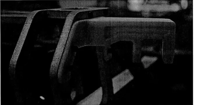
[3.-.3] Secondary And Synchro Link
Figure 3-25: The secondary and synchro links
The secondary link connects the rear powertrain module to the main bars, and the synchro link connects the front powertrain to the secondary link. Both elements underwent extensive motion analysis FEA to create the planar assemblies required to replicate the functionality of the originally to-be-casted pieces. With CFRP plates covering 6o6i-T6 Al lattice structures, each piece is geometrically optimized to handle expected static and dynamic loading conditions throughout the entire folding sequence. Matching the pivot points available on the front and rear powertrain modules, the synchro link has one pivot point interfacing with it, and the secondary link has two. This allows the linkage pivot points to overlap laterally, thus enabling the wheelbase reduction previously described.