Design of a Small Folding Table for a Wheelchair
by Emily Obert
Submitted to the
Department of Mechanical Engineering
in Partial Fulfillment of the Requirements for the Degree of Bachelor of Science
at the
Massachusetts Institute of Technology June 2011
© 2011 Emily Obert All rights reserved
The author hereby grants to MIT permission to reproduce and to
distribute publicly paper and electronic copies of this thesis document in whole or in part in any medium now known or hereafter created.
Signature of Author
... Department of Mechanical Engineering
May 6, 2011
Certified by
... David Wallace Associate Professor of Mechanical Engineering
Thesis Supervisor
Accepted by
... John H. Lienhard V Collins Professor of Mechanical Engineering Chairman, Undergraduate Thesis Committee
Design of a Small Folding Table for a Wheelchair
by Emily Obert
Submitted to the
Department of Mechanical Engineering
in Partial Fulfillment of the Requirements for the Degree of Bachelor of Science
at the
Massachusetts Institute of Technology
Abstract
At receptions, parties, networking events, or other social functions, able-bodied people move around the room from conversation to conversation carrying a drink and/or a little plate of food. People who use wheelchairs for mobility are limited by their need to use their hands to push their wheelchair about the room. This thesis addresses this need through the design of a table that can attach to a manual wheelchair to hold food and drink. The table is engineered to be lightweight, small enough to fit in a backpack, hold a wine glass, and prevent food from sliding off its surface when the wheelchair goes over bumps. The thesis documents the design of the table— it is a simple, contemporary design made primarily of aluminum and vinyl. Preliminary mockups were built to test and refine the table concept and key details, while a detailed digital model for the final design was developed. Because the market for such a product is very small, the table will be manufactured by CNC machining and it will cost upwards of $100.
Acknowledgments
I give many thanks to Prof. David Wallace and my mother, Cathy Poff, without whom this thesis would not be possible. Their support is unending, and they always have just the right thing to say. I’d also like to thank Burton Third and the Mechanical Engineering department for being so flexible and eager to help me throughout the semester with anything I needed.
Table of Contents 1. Introduction 7 2. User Requirements 7 3. Final Design 8 3.1 TiLite™ Clamp 11 3.2 Flexures 12 4. Design Process 18
4.1 Initial Ideation and Idea Selection 18
4.2 Mock-ups 19
4.3 Sketch Models 22
5. Business Case 25
5.1 Market for Manual Wheelchairs and Miscellaneous Patient Aids 25
5.2 Product Comparison 26
5.3 Financials 27
6. Conclusions 28
List of Figures
Figure 1: Rendering of the table (a) in a set position and (b) folded up
8 Figure 2: Sketch model mounted on the chair in the same manner as the final design 9
Figure 3: A party plate with cutout for holding a wine glass [2] 9
Figure 4: Cross-section view of table in upright position with a focus on the vinyl pad in Detail B 10 Figure 5: Rendering of the table with a can from the users perspective 11 Figure 6: TiLite™ Ridgid (as opposed to cloth) Sideguard and clamp design [4] 12
Figure 7: TiLite™ Rigid Sideguard Clamp [4] 12
Figure 8: Isometric view of the flexures 13
Figure 9: Profile geometry of the table 13
Figure 10: Free body diagram of the tabletop 14
Figure 11: Side profile of flexures. The force NB is pushing on the flexures and the post behind them at an angle of θ. The force on the flexures is NBsinθ. This load is shared equally between the two.
15
Figure 12: Flexure geometry. The force of the tabletop is resolved as (NBsinθ)/2 straight down, a distance x from the tip of the flexure and a distance l from the place where the flexure will bend.
16
Figure 13: This prototype uses a groove to support the table and can be seen (a) on the chair, (b) folded up on the table, (c) latched and (d) unlatched.
19
Figure 14: This prototype uses a shear pin and can be seen (a) on the chair without a tabletop, (b) folded up on the table, (c) unhinged and (d) assembled.
20
Figure 15: The flexure mock-up is shown (a) supporting the table (b) and with the table folded up. 21 Figure 16: Two-bar linkage (a) in the collapsed (b) and table-in-use positions. 22
Figure 17: Two-bar Linkage Prototype 23
Figure 18: Flexure Mock-up 24
Figure 19: Wheelchair tables on the market today [9][10][11][12] 26
Figure 20: A plot of wheelchair tables and other accessories where the blue line is the mean price of the wheelchair tables ($141.15), the red line is the mean of the wheelchair accessories ($59.33) and the green line is the mean price for all items ($97.32).
27
List of Tables
Table 1: Five- year projection of revenue, costs, expenses, and earnings for a company producing the table in this thesis
1. Introduction
At receptions, parties, networking events, or other social functions, able-bodied people move around the room from conversation to conversation carrying a drink and/or a small plate of food. It is common to hear people joke about needing a third hand to share cards or pickup other items. For people in a wheelchair this is even more of a challenge, since both hands are needed for mobility—to operate their chair. They are even more limited than the average person, when holding a drink and plate of food.
Preliminary market research suggests that no existing products serve the needs of manual wheelchair users in a social situation with food and drink. The objective of this thesis is to address this need with a small table. Users suggested that the table must be engineered to be lightweight, small enough to fit in a backpack, able to hold a wine glass and able to prevent food from sliding off when the wheelchair goes over thresholds.
A working prototype for a table was developed after performing human-use studies, sketch models and user testing. This thesis documents the design process and rationale, as well as provides preliminary testing results and a business model for the new prototype.
2. User Requirements
After speaking to a wheelchair user, it was determined that a small table for social events would primarily need to hold a drink and hold food. It was suggested that it would be great if the table could hold a wine glass and other oddly shaped cups, as well as large plate; and it would be even better if the table could keep the cups from spilling as the chair moved over bumps. At the very least, the table must hold a party cup and a small plate of food. Users also wanted to be able to write on the table. From studies done on writer’s cramp, a maximum pen tip force for writing would be 2.5 N [1] and the users hand is assumed to be about the same, so that would be about 5 N.
Since it is not desirable to have a table all the time, users wanted the table to be lightweight and easily fit in a bag hanging on their wheelchair. This is often a backpack or messenger bag. It was suggested that perhaps the table could just swivel away behind the chair, but wheelchair users felt that having accessories attached to the wheelchair itself would be bothersome during much of the day.
Many manual wheelchair users have light, sporty chairs made out of aluminum or titanium. To match the table to the wheelchairs, the table should be good looking and have a silver and black color scheme, which will coordinate with accent colors on almost every manual fixed-frame wheelchair.
Although writing only puts about 5 N of force on the table surface, the table should be able to hold up to more than just writing. It should be able to hold a half-gallon of milk (19 N) because events often have pitchers with iced tea or lemonade, which are about a half-gallon in volume. The user might set a pitcher on the table before pouring a drink. Also, there is always a chance that a user will put more weight on the lightweight table than it was designed for. Rather than breaking, the table should be designed to collapse in a way that the user could easily put it back together without replacing any parts. The table should also use an attachment system that
would allow it to be used on various types of wheelchairs for maximum flexibility and largest market share.
3. Final Design
The final design of the wheelchair table is made of primarily of cast aluminum. It has injection molded polypropylene flexures, an injection molded vinyl top, steel fasteners and an existing bracket design from TiLite, a lightweight wheelchair manufacturer. Figure 1A shows an overall view of the table and Fig. 1B shows the table in its folded position. Figure 2 is a
photograph of a sketch model, which attaches to the wheelchair in the same manner as the final design. The table itself has 11 pieces and the clamp has 10 pieces. The table is comprised of three aluminum parts, a vinyl table-top insert, two polypropylene flexures, two steel pins (one for each hinge) and four 3/8 inch #00-90 steel machine screws used to secure the flexures. Most edges on the table have a 1 mm radius to give it a crisp, clean look.
Figure 2: Sketch model mounted on the chair in the same manner as the final design
The tabletop is 7.2 by 9.2 inches and will easily fit a cup and a small plate. It can also fit a cup and a full size plate, if user is willing to let the full size plate hang somewhat precariously off the front of the table. The hole on the top right corner of the table is modeled after the hole in party plates made to hold wine glasses, like that shown in Fig. 3. The design has the cutout in a place where the stem of the wine glass will not hit the users leg or the wheel of the wheelchair.
If the table is used to hold glasses, then having a table that only fits on the right side of a wheelchair is acceptable because glasses go on the right in a table setting; however, if the user is left handed and intends to write on the table a lot, the top and vinyl inset would have to be manufactured in a mirror image. All of the other parts are symmetric. Having a second mold for a tabletop could significantly increase the initial price of manufacturing.
The dimensions of the table when folded, as shown in Fig. 1B, are 11.25 by 7.25 by 0.95 inches. The tabletop when folded for storage is smaller than a laptop and will easily fit into a backpack. The hinge design allows the table’s three main pieces to fold completely flat.
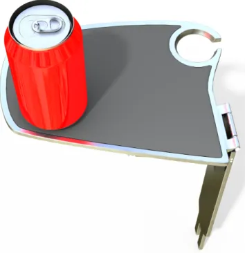
The table has a black vinyl insert. This insert is 2 mm thick and is made of the same material as covers people use for drafting tables. This material was chosen because it is good to write on and has a texture that makes paper (as well as cups and plates) cling to it. As seen in Detail B in Fig. 4, the table has a lip to hold the pad in and the pad has some clearance around it so that it will not bubble, something that is likely to happen if it was a tight fit. Since the vinyl grips cups and plates, the user does not have to worry about a can, like the one in Fig. 5, falling off the table.
Figure 4: Cross-section view of table in upright position with a focus on the vinyl pad in
Detail B A A .13 .13 4.01 SECTION A-A .08 .03 .25 DETAIL B SCALE 2 : 1
Figure 5: Rendering of the table with a can from the users perspective
Also visible in Fig. 4, is the curvature of the support beam. The support was curved at the end to increase the contact area between the flexure and the support and direct the forces at the end of the beam in a downward direction. The flexures are discussed in further detail in Section 3.2.
3.1 TiLite™ Clamp
This table design utilizes a clamp, pictured in Figs. 6 and 7, that is already used by TiLite [3]. Currently, the clamp is used to hold sideguards. Sideguards are pieces of plastic or metal between the user and the wheels of the chair that prevent the users clothes from both getting tangled in the wheels and getting covered in dirt from the street. Ideally, if a user ordered sideguards that use the standard clamp, the table would already be included in the price and automatically ship with the chair. Alternatively, the table could be an accessory included on the wheelchair order form, much like the cargo nets and backpacks already on TiLite’s form.
The TiLite clamp design is good for use with this table because it has a pin that secures the clamp to the pipe of the chair that keeps the clamp, and subsequently the table, from rotating, even when heavily loaded. The pin does require a hole, so that increases the amount of work the user must do to install this clamp on a chair that was not shipped with the sideguards mounted in this manner. Some users may be unwilling to add a hole to their wheelchair and would not buy the table for this reason. This clamp could be sold for different wheelchair pipe diameters, but that would increase the initial price of manufacturing.
Figure 6: TiLite™ Ridgid (as opposed to cloth) Sideguard and clamp design [4]
Figure 7: TiLite™ Rigid Sideguard Clamp [4] 3.2 Flexures
It was necessary to design a flexure for the table to limit the stresses on the hinges and clamp in the design. In the case where the user overloads the table, it would be preferable that the table collapse rather than break in an irreparable manner. Too much load on the table could shear the pin (labeled as 14 in Fig. 6) in the clamp design or cause either of the hinges to fail. When the flexures bend outwards, the support drops in between them and the heavy load will slide off the tabletop into the users lap. It would be dangerous if the user collapses the table with a load that is not only heavy, but also at a high temperature. The user would have to be cautioned against doing this and against cooking with the table. It was designed for social events, not meal preparation. An isometric view of the flexure design can be seen in Fig. 8.
Figure 8: Isometric view of the flexures
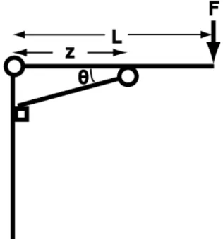
The flexure design takes into account the geometry of the table, the forces on the table, the geometry of the flexures, the material of the flexures and the amount the flexures need to deform to allow the table support to slip through. Fig. 9 shows the geometry of the table, where z is the x-distance from the hinge of the post to the hinge of the support, L is the x-distance from the hinge to the point the farthest away on the table, F is the greatest allowable load to be applied to the table, and θ is the angle between the table and the support beam.
A free-body diagram of the tabletop is shown in Fig. 10, where NB is the force exerted by the
support on the tabletop, RYA is the reaction force at the hinge in the y-direction and RXA is the
reaction at the hinge in the x-direction.
Figure 10: Free body diagram of the tabletop
To find the forces on the flexure, the force exerted by the support under a load F, must be found. Since the table is a static structure, the sum of the forces and the sum of the moments must equal zero. The force and moment balances are shown in Eqs. (1a), (1b) and (1c).
€ Fx= RXA + NBcosθ= 0
∑
(1a) € Fy = RYA + NBsinθ− F = 0∑
(1b) € MZA = NBsinθ ⋅ z − F ⋅ L = 0∑
(1c)Using the sum of the moments around the support hinge in Eq. (1c), one can solve for NB,
as shown in Eq. (2).
€
NB = FL
z sinθ (2)
To be sure that the hinge can withstand the forces on it, Eq. (2) is substituted into Eqns. (1a) and (1b). This yields Eqs. (3) and (4).
RXA = FL
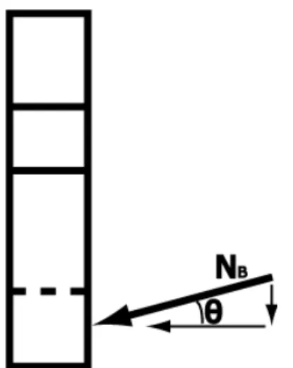
To determine the magnitude of the force that causes the flexures to deform, it is important to consider the angle of the support. The force, NB, that pushes on the flexures is NBsinθ because
the rest of NB is directed at the post behind the flexure. The load on the flexures is shared equally
between the two. This can be seen more clearly in Fig. 11.
Figure 11: Side profile of flexures. The force NB is pushing on the flexures and the post behind them at an angle of θ. The force on the flexures is NBsinθ. This load is shared equally between the two.
The geometry of one of the flexures is shown in Fig. 12, where w is the width of the top of the flexure, h is the width of the flexure between the two notches, r is the radius of the notches, l is the distance in the y-direction from the center of the notches to the place where the support beam rests on the flexure, ϕ is the angle at the “toe” of the boot, and x is the distance in the x-direction from the tip of the flexure to the place where the support beam rests on the flexure. The depth of the flexure is t, although it is not shown in this diagram.
Figure 12: Flexure geometry. The force of the tabletop is resolved as (NBsinθ)/2 straight down, a distance x from the tip of the flexure and a distance l from the place where the flexure will bend.
The for the support beam to slip, the flexure must bend enough that the tip of the flexure moves a horizontal distance of x. Eq. (5) describes x in terms of l and γ by using the small angle approximation
€
x = lsinγ (5)
where γ is the angle of the flexure from vertical as the bottom half pivots around a point directly between the two cutouts, a distance r + h/2 from the left side of the flexure. Eq. (6) is a
reorganization of Eq. (5), and says that
€ γ = sin−1 x l (6)
If it is assumed that most of the elastic deformation comes from the bottom half of the cutout, then the radius of the cutout, as shown in Eq. (7) is
′ r = r
cosγ (7)
€
ε =( ′ r + r) − 2r
2r (8)
The standard equation for stress under for beam bending is modified with a k-factor to account for the notched geometry [5]. The value of k is based on geometry and can be found using tables. This modified equation can be seen in Eq. (9),
€
σ = kMc
I (9)
where M at the point under consideration, c is the distance of the point away from the neutral axis of the bending, and I is the moment of inertia of the beam in the direction that resists bending. The downward force on one of the flexures, Fflex, is describing in Eq. (10).
€
Fflex= NBsinθ
2 =
FL
2z (10)
To find M, the moment on the flexure, which is primarily in the y-direction, must be resolved into a component in the x-direction because it is the force perpendicular to l, which contributes to the deflection of the flexure. The moment on the flexure with the resolved force, the distance to the edge of the notch and the moment of inertia are described in Eqns. (11a), (11b) and (11c) respectively.
€
M = Fflexlcosφ sinφ (11a)
€ c = h /2 (11b) € I = 1 12th 3 (11c)
By combining Eqns. (9), (10) and (11), the maximum stress at the root of the notch can be shown in Eq. (12) to be € σmax = k FL z lsinφ cosφ 1 3th 2 (12)
Equation (13) defines stress, σ, as
€
σ = Eε (13)
where E is the Young’s Modulus of the material [5]. In this case, the Young’s Modulus is that of polypropylene and strain, ε, is defined by geometry in Eq. (8), so the stress of the flexure to allow failure under a load F is known. Using MathCAD, the geometry of the flexure was
determined by iterating so that σmax was equal to Eε. It was then verified that σmax was in the
elastic regime for polypropylene, so that the flexure would not fatigue.
The force on the table used for these calculations was that of a half-gallon of milk, with a safety factor of 1.25. The final dimensions of the flexures are a width (w) of 6 mm, a length (l) of 16 mm, a radius (r) of 1 mm, a thickness (t) of 10 mm and angle ϕ of 45°. The k-factor was 1.45 from the plots in Mechanics of Materials [5].
4. Design Process
4.1 Initial Ideation and Idea Selection
In an initial brainstorming session, some breakaway mechanisms were discussed like a release clip or a shear pin for a support beam. Different cups could be accommodated with adhesive pads that peel off like a lint removal wand, gel in a pocket that could squish around the base of a cup, different diameter holes or a strap. A wine glass could be accommodated with a notch. Glasses could be kept from spilling with an active control system, some springs to decouple the table from the chair, a cutout for the cup or a swinging basket.
Many fixed-frame chairs (wheelchairs that do not fold in half) have dump, which means the seat tilts the rider towards the back. If the table is connected to the pipe under the seat, its connector will be on an angle. If was important for the table to be level, it could be done with an active control system or a pivot point with a wing nut to lock everything in place.
Some ideas for how the table could fit in a backpack were a telescoping neck or a neck that folds up like a pocketknife. It was discussed that the neck could be short enough to fit in a bag without folding.
Chair attachment ideas included brackets that fit around the pipe under the seat with arms that butt up against the seat cushion to keep the bracket from rotating, a bracket with a strap that doubles back on itself to tighten down, a bracket with a strap and a v-shaped section to accommodate different sized pipes and a bracket that functions a lot like a three jaw chuck.
4.2 Mock-ups
The first round of mock-ups focused on the size of the table and the ability of the table to be set up and flattened repeatedly. The table, in Fig. 13, uses a groove to support the table. When flattened, the table was nearly 24 inches in length and much too large for a backpack. As pictured in Fig. 13A, the tabletop was also uncomfortably close to the users body and much too high.
Figure 13: This prototype uses a groove to support the table and can be seen (a) on the
Rather than a groove, the second mock-up, shown in Fig. 14, used a pin to hold the table together. This pin could be a shear pin to prevent harder-to-replace pieces from breaking. The shear pin, pictured in Fig. 14C, was easy to lose and took a lot of fine motor skills to put into place. This would be difficult for someone with limited vision or hand movement.
Figure 14: This prototype uses a shear pin and can be seen (a) on the chair without a
Because of the many problems associated with a shear pin, it was decided that the next round of mock-ups would explore flexure options to handle overloading. Figure 15 is a mock-up of a flexure design in which the flexures bend outwards under a heavy load, causing the support bar to slip downwards.
Figure 15: The flexure mock-up is shown (a) supporting the table (b) and with the table
The mock-up in Fig. 16 explores a different folding mechanism. The two-bar linkage allows the table to fold up and out. The flexure in the linkage mock-up would be where the links connect to the table. Under too much weight, the table would pop loose from the links.
Figure 16: Two-bar linkage (a) in the collapsed (b) and table-in-use positions. 4.3 Sketch Models
A second iteration of the two-bar linkage table is shown in Fig. 17. The linkages, table support and table-link attachment were 3D printed with a Dimension printer. The tabletop and supports were cut out of ABS on a laser cutter. The Dycem Non-Slip is the yellow material, which was also laser cut, was used to give the table a better grip.
Figure 17: Two-bar Linkage Prototype
The yellow section of the table prevents cups and bottles from sliding off the table. The section was helpful to the user, but it needed to be larger. There was not anything the user did not want on the yellow section, as long and she could write on it with ease. This desire is accommodated in the final design by covering most of the tabletop with a vinyl pad. Dycem clings to a smooth surface with ease, but the raster setting on the laser cutter left a texture when it cut the indentation for the yellow section, so the Dycem would fall out when the table was folded up. On one hand it was helpful that the Dycem could be removed for washing, but on the other hand the user should not have to look for pieces to the table before she can use it. The final design uses a lip, as picture in Fig. 4, to solve this problem. If the vinyl in the final design needs replacing, the user could remove it, but the lip around the edge will keep it secured otherwise.
The user liked the shape of the table. It was a good distance away from her stomach. It could have had a little less taper, so it could hold a little more. The wine glass notch stuck out much too far. The stem had plenty of clearance over the wheel, but the notch needed to be bigger to accommodate the curvature of the glass. The final design has a hole of just of 1.5 inches. This lets large wine glasses settle into the curve, but prevents champagne flutes from falling through.
In Fig. 17B, it can be seen that the clearance above the leg was about 1.5 inches. This is a reasonable amount, but for a larger person this could be a problem. The table height was comfortable for cups, plates and writing, so making it taller unnecessarily could compromise ergonomics.
This table, when fully folded in the storage position, is 2.25 inches wide. The load at the pivot point where the linkage and the table meet is related to length of the support by 1/x. In this case the support is 2 inches. The larger the distance, the lower the load at the pivot and the higher the load the table can carry.
It was difficult to test the linkage flexure style because the ABS was too brittle. The flexure snapped rather than elastically deforming. Even if the flexure had worked, when the flexure deforms and the tabletop pops loose, it is quite shocking to the user. The tabletop will often fall on the floor and it is a scramble to get it back to reassemble the table. In the final design, no parts come loose.
The linkages allow the tabletop to slide back and forth over the support, which is undesirable because the sloshing makes cups tip off. Future iterations could be done with a single link and could include a geometric feature on the support and its complement on the tabletop to lock everything in place.
A second iteration of the table with the boot shaped flexure can be seen in Fig. 18. The two boot-shaped flexures were 3D printed on a Dimension printer. The rest of the table is made out of ¼ inch ABS, which was cut with a laser cutter. The support and the post were attached to the tabletop with premade hinges. The post was 10 inches tall.
Figure 18: Flexure Mock-up
Bottles kept falling off the table. During testing Dycem was taped to the table. With the Dycem, bottles, cups and plates stayed on the table even over bumps. This testing further inspired the vinyl pad on the final design.
The support beam can be seen touching the user’s leg in Fig. 18A. This problem would be exacerbated for a larger person. Although making the table higher would be less ergonomic, moving the table farther away from the users body would compensate for the change in height. Decreasing the angle between the brace (support beam) and the user’s leg, would give the user more space. Decreasing the angle would also, increase the reaction forces at the pin, but as long as the hinge is designed for those forces they are not a problem. The final design has a post that is 1.5 inches taller and the angle between the support and the tabletop was decreased from 45 degrees to 15 degrees.
The table in the storage position is 1-3/8 inches wide. Using thinner sheets of material and designing thinner flexures could further decrease this width. The final design is even more compact, despite having a curved support beam. In general, the thinness when folded is a strength of this design.
In the sketch model, the flexures performed as expected. Unfortunately, the table was designed such that the ABS post and tabletop would deflect more than a centimeter before the support pops through the flexure. In future iterations, the table and post will be made out of aluminum, which will not bend under such low loads. The flexures did exhibit some signs of fatigue because they were made of ABS.
When the table was overloaded, it would collapse, and the heavy load would start to slide across the table into the users lap. This could be dangerous for hot items. A reasonable weight threshold would need to be set for this design. The final design of the flexures was hardly changed, although the dimensions of the flexures changed because the final design material was polypropylene, as opposed to ABS.
5. Business Case
5.1 Market for Manual Wheelchairs and Miscellaneous Patient Aids
In the United States, there are an estimated 1.5 million manual wheelchair users [6]. The estimated market for manual wheelchairs is $264 million, $103 million of that total belonging to Medicare expenditures alone [7]. The wheelchair table would fall into the category of miscellaneous patient aids, since tables are currently sold separately from wheelchairs. In 1998, the miscellaneous expenditures totaled approximately $164 million, 10% of the Home Medical Equipment Market [7].
In the US, “demand for wheelchairs and other personal mobility devices is projected to increase more than five percent per year through 2010 to approximately $3.6 billion,” but this total includes not only wheelchairs, scooters and lifts, but also golf cars, in-plant personnel carriers, commercial vehicles, trams, and man lifts [8]. Despite the variety in products under consideration, the report states that demand growth will be similar for both product segments. For this business case it is assumed that the growth in demand for wheelchair accessories will mirror that of wheelchairs themselves.
The manual wheelchair accessory market is small. It could be considered a portion of either the manual wheelchair market or a portion of the miscellaneous patient aid market. An average price of a manual wheelchair is $2500. If the mean price of wheelchair accessories and tables is about $100, see Fig. 20 in Section 5.2, then accessories would be about 4% of the manual wheelchair market. A more conservative estimate would be 1%. So the manual wheelchair accessory market could be estimated at $2.64 million. This is a small market size, but there are not very many manual wheelchair users. This would be an average spending of $2.2 dollars per manual wheelchair user, an amount growing at 5% per year. Modifying the clamping system to allow the table to fit a powered wheelchair could expand the market size by another 94,000 users [7]. Most powered wheelchairs chairs have armrests and many users have limited function in their upper extremities; so further research into the needs of powered wheelchair users would be necessary.
The specific market for the table in this thesis is a manual wheelchair user with a fixed-frame chair. Chair manufacturers like TiLite and Quickie would sell the table either bundled with a wheelchair order or in the accessory sections of their websites. Medical equipment dealers that work with hospitals and patients to place wheelchair orders would also sell the table. Some of these dealers sell equipment on Amazon.com and ebay.com, so it is possible the table will be sold on those websites as well.
Because the table fits in the same clamp as the TiLite removable side-guards, it would make sense to have the table as an add-on for this brand of chair. TiLite wheelchairs can cost over $10,000 (a price mostly paid by insurance companies), so a $100 table would only increase the price by 1%, a small amount.
5.2 Product Comparison
Most of the wheelchair tables on the market hook onto armrests. Most fixed-frame wheelchair users do not use armrests. This table serves users without armrests. Some of the options on the market are shown in Fig. 19.
Figure 19: Wheelchair tables on the market today [9][10][11][12]
The ezEnabler pictured in the bottom left-hand corner is the only table on the market that would work on a chair without an armrest. It retails for $80.70. Figure 20 shows prices for wheelchair accessories and specifically wheelchair tables. The mean price for wheelchair tables is $141, while the mean price for accessories is $59. The overall mean price is $97. If the table could retail for $100 that would be ideal, but because of the materials and machining costs, it will probably retail for around $200, which is still cheaper than some products on the market, but is not as competitive of a position.
Figure 20: A plot of wheelchair tables and other accessories where the blue line is the
mean price of the wheelchair tables ($141.15), the red line is the mean of the wheelchair accessories ($59.33) and the green line is the mean price for all items ($97.32).
5.3 Financials
Because the volume of tables per year is so low, die casting the tables does not make sense, since tooling would cost many thousands of dollars—instead these tables will be machined. As an estimate for this business case shown in Table 1, the cost of materials is based on the weight of the table with a price of $4 a kilogram for 6061-Aluminum and a 300% markup [13]. Using the cost of machining was estimated to be $450 for setup and tooling with $30 of processing for each part. Taxes are assumed to be 50% of earnings.
This product would break even in the second year and the Internal Rate of Revenue would be 0.49 with a starting investment of $23,000 with a selling price of $100 per table.
Table 1: Five-year projection of revenue, costs, expenses, and earnings for a company producing the
table in this thesis
6. Conclusions
Wheelchair users need the option of a contemporary, elegant, compact table for cocktail parties and other social events. The design presented in this thesis satisfies many wheelchair users’ need for a simple, portable and lightweight design. It has a notch to hold a wine glass, as well as a vinyl no-slip surface that prevents cups and plates from sliding off the tabletop and is a good surface on which to write. It quickly attaches to and from the wheelchair. Once detached, it folds flat and can fit in a backpack or large purse. It has a breakaway mechanism to prevent damage when the table is overloaded and utilizes an already existing clamp design to attach to a wheelchair.
Unfortunately, because the market is small, the price of the table is estimated to be $200. A price point around $100 would match the industry average for a wheel chair table.
Compromising on price would mean compromising on materials. It would be possible to make this table design out of plastic rather than aluminum, but that would limit the load it would be able to carry and likely reduce the aesthetic value and perceived quality of the device.
In the coming months, the table design will be fabricated and extensively tested. After another design iteration, the design will be pitched to TiLite and Quickie, the two largest manufacturers of manual wheelchairs in the United States, with the hope of including the table as an option for wheelchair users through their websites and wheelchair sales.
References
[1] Schneider, A. S., et al. "Writing Kinematics and Pen Forces in Writer’s Cramp: Effects of Task and Clinical Subtype." Clinical Neurophysiology 121.11 (2010): 1898-907.
[2] HomeandWine.com. “Hors D' Ourves Plate - Buffet & Party Plate with built-in Stemware Holder.”<
http://www.amazon.com/Hors-Ourves-Plate-built--Stemware/dp/B002BU3RSY/ref=sr_1_4?ie=UTF8&qid=1305918535&sr=8-4>. [3] TiLite. “Welcome to TiLite.” <www.tilite.com/home.php>.
[4] TiLite. “Sideguard Clamp 1.25” Assembly.”
<http://estore.tilite.com/ecommerce/CatalogItemDetail.aspx?CID=426&IID=1019>.
[5] Hibbeler, R. C. Mechanics of Materials. 7th ed. Upper Saddle River, N.J.: Prentice Hall, 2008.
[6] Kaye, Stephen H., Taewoon Kang, and Mitchell P. LaPlante. "Wheelchair Use in the United States." 2002. <http://dsc.ucsf.edu/publication.php>.
[7] “The Wheeled Mobility Market.”
<http://www.wheelchairnet.org/wcn_wcu/Research/StakeholderDocs/PDFs/wpf_wheelchairsu
mmary_doc.pdf>.
[8] Freedonia Group Inc. "Wheelchairs & Other Personal Mobility Devices." <http://www.marketresearch.com/product/display.asp?productid=1354455&xs=r&SID=882784 20-510478014-456016682&curr=USD>.
[9] LivingEasy. “ezEnabler.” < http://www.amazon.com/LivingEaZy-ezEnabler/dp/B002FKO0VS>.
[10] Sales Stores. “Mabis 505-4016-0400 Wheelchair Tray, Hardwood.” <http://salestores.com/mabis5054016.html>.
[11] Sears. “MABIS DMI HEALTHCARE Clear Acrylic Wheelchair Tray Velcro Wheel Chair.”
<http://www.sears.com/shc/s/p_10153_12605_SPM1648495801P?sid=IDx20101019x00001a&
ci_src=14110944&ci_sku=SPM1648495801>.
[12] Quickie. “Wheelchair Trays.” http://www.quickie-wheelchairs.com/category/Wheelchair-Trays/527
[13] Ulrich, Karl T., and Steven D. Eppinger. Product Design and Development. 4th ed. Boston: McGraw-Hill Higher Education, 2008.


![Figure 6: TiLite™ Ridgid (as opposed to cloth) Sideguard and clamp design [4]](https://thumb-eu.123doks.com/thumbv2/123doknet/14685388.560125/12.918.261.704.107.329/figure-tilite-ridgid-opposed-cloth-sideguard-clamp-design.webp)