DESIGN OF A BUILDING STRUCTURAL SKIN USING MULTI-OBJECTIVE OPTIMIZATION TECHNIQUES
BY
Riccardo Merello
Laurea, Ingegneria Civile - Strutture Universitii di Genova
SUBMITTED TO THE DEPARTMENT OF CIVIL AND ENVIRONMENTAL
ENGINEERING IN PARTIAL FULFILLMENT OF THE REQUIREMENTS FOR THE
DEGREE OF MASTER OF ENGINEERING IN
CIVIL
AND
ENVIRONMENTAL ENGINEERINGAT THE
JUNE 2006
02006 Riccardo Merello All rights reserved.
The author hereby grants to MIT permission to reproduce and to distribute publicly paper and electronic copies of this thesis document in whole or in part
in any medium now known or hereafter created.
i
-
hSignature of Author: U( \
Department of Civil and Environmental Engineering May 23,2006
A
n
A
Certified by: I - a - - -
Jerome J. Connor Professor of Civil and Environmental Engineering Thesis Supervisor
A d s I
I
/,
Accepted by: t,-Clcl w u - r r a
-
r n I~ n d r w . Whittle Chairman, Departmental Committee f o ~ Graduate Students
DESIGN OF A BUILDING STRUCTURAL SKIN USING MULTI-OBJECTIVE OPTIMIZATION TECHNIQUES
BY
Riccardo Mere110
Submitted to the Department of Civil and Environmental Engineering On May 23", 2006 in Partial Fulfillment of the Requirements for the Degree of
Master of Engineering in Civil and Environmental Engineering
ABSTRACT
Multi-disciplinary System Design Optimization was used to design the geometry and to select the materials for the structural faqade of a building. A multi-objective optimization model was developed, capable of optimizing the design of the facade on the basis of a lighting analysis of the interior, of a thermal analysis of the cooling loads corresponding to the skin configuration, and of a finite elements analysis of the supporting structure. The system also considers the need for transparency in the faqade due to view requirements of the occupants, and the cost of
cladding materials. A scalarization approach to MDO, via utility functions, was chosen, and the overall objective function was optimized using Genetic Algorithms.
Thesis Supervisor: Jerome J
.
ConnorTo the memory of my beloved uncle, Giorgio De Maestri. Grazie, Zio, per il tuo affetto e il tuo sostegno. Nessuna parola puo dire il vuoto che hai lasciato.
Acknowledgments
I am greatly indebted to Professor Jerome Connor, whose precious advices and wise guidance supported me while I was writing this thesis, and all throughout the year. Also, this work would not exist without the contribution of Anas Alfaris, who has been a wondrous team-mate and a friend during these tough months.
My gratitude goes to the partners and the managers of D'Appolonia S.p.A., for encouraging me to apply to M.I.T., and for sponsoring this enriching experience.
Thanks to my whole family for being there, even from a long distance, and to Maria Clara and all my friends in Italy, for their invaluable support.
Finally, I want to express my thankfulness to the friends who made these days so memorable: Anatoly, Lauren, Gordana, Rossella, and all the Mooseheads.
Table of
contents
Acknowledgments...
4...
Table of figures 7...
Preface 8 Chapter 1 : Introduction...
9 1.
1 The Problem...
13 1.1.1 Architecture...
13 1.
1.
2 Lighting...
14...
1.
1.
3 Thermal 15 1.
1.
4 Structural...
16 1.1.5 Economy...
171.2 Definition of the design object
...
171.2.1 Geometry
...
171.2.2 Materials
...
18Chapter 2: The idea: using MSDO
...
20...
2.1 What is MSDO? 2 0 2.2 History...
212.3 How does MSDO work?
...
242.3.1 Problem formulation
...
24...
2.3.2 Design variables 2 4...
2.3.3 Constraints 24 2.3.4 Objectives...
25...
2.3.5 Models 2 5...
2.3.6 Standard form 2 5...
2.3.7 Methodology 26 2.3.8 Problem solution (Scalarization approach)...
27...
Chapter 3: Design Optimization
...
293.1 Architecture of the Model
...
303.1.1 Design Vector
...
30 3.1.2 Geometry module...
32 3.1.3 Initialization Module...
33 3.1.4 Lighting Module...
33...
3.1.5 Thermal 34 3.1.6 Architecture...
35 3.1.7 Structure...
36...
3.1.8 Economy 39...
3.1.9 Performance 4 0...
3.1.1 0 Optimizer 41 3.2 Software & Hardware Tools...
43...
3.3 Multi-objective Optimization 44...
3.3.1 Optimization Algorithm 4 4 3.3.2 Genetic Algorithm parameters...
44Chapter 4: Results
...
47 4.1 Final results...
47 4.2 Diachronic evolution...
49 Chapter 5: Conclusions...
51...
5.1 Openings 52 Appendix A: Genetic Algorithms...
53A.2 History
...
53...
A.3 Operation of a GA 54 A.4 Initialization...
5 4 A.5 Selection...
5 4...
A.6 Reproduction 55 A.7 Termination...
55 References...
56Table of figures
Figure 2
.
Reorganization of design process in aeronautic industry to gain informationearlier and to retain design freedom longer
...
11Figure 3
.
Sequential vs Concurrent Design (design of an aircraft wing)...
12Figure 4
.
Transparency in architecture: the fagade of the Fondation Cartier in Paris. by architect Jean Nouvel...
14Figure 5
.
Daylighting for a Classroom...
15Figure 6
.
Numerical illuminance analysis of the above classroom...
15Figure 7
.
Energy consumption in residential buildings. end-use split...
16Figure 8
.
The hexagonal grid of the structure ... 18Figure 9 -Multi-disciplinary System Design Optimization framework
...
20Figure 10
.
Design requirement growth for aerospace vehicles...
23Figure 1 1 Working scheme of the optimization system
...
29Figure 12
-
Complete architecture of the optimization system...
30Figure 13
-
Graphical representation of the geometric Design Variables...
31Figure 14
-
Graphical representation of the materials Design Variables...
32Figure 15
.
A screenshot of a solution, from CATIA...
33Figure 16
.
Scheme of the Lighting module...
34Figure 17
.
Scheme of the Thermal module...
35Figure 18
.
Scheme of the Architecture module...
36Figure 19
.
Scheme of the Structure module...
37Figure 20
.
Scheme of the Economy module...
39Figure 21
.
Structure of the Utility Functions...
40Figure 22
.
Graphical representation of the geometric constraints...
42Figure 23
.
Geometry and materials distribution for final design...
47Figure 24
.
Render of final design...
48Figure 25
.
Improvement of the objective function over the GA's generations...
49...
Figure 26.
Evolution of design during the optimization process 50"Fatti non foste a viver come bruti, ma per seguir virtute e canoscenza." (Dante Alighieri, Divina Commedia, Inferno, Canto XXVI, 1 19
-
120)"Avdpa pol t v v ~ m Mociaa ~ O A ~ T ~ O T T O V , os paAa M a
ITA~yxeq, E T K ~ T p 0 i q ~ I E ~ ~ V ~ T O A ~ E ~ ~ O V ~ ~ K ~ D E V . .
."
(Homer, Odyssey, Book 1, 1 - 2)Preface
This study initially originated from a Project for the course of "Multidisciplinary System Design Optimization" (MSDO), taught at M.I.T. by Prof. 0. De Weck and Prof. K. Willcox. The course introduced the author and his team-mates, Mr. Anas Alfaris and
Mr. P. Geyer, to the concepts of optimization-driven design.
Professor De Weck, in particular, encouraged the team to apply MSDO to such an "atypical" design object as a building skin, since these techniques, widely applied to the domains of Aeronautic & Astronautic Engineering, are seldom used in architecture and civil engineering.
Chapter 1
:
Introduction
Numerical optimization can be applied to the design of structures in order to shape an architectural body and to design its components in such a way that a number of objectives are optimized and certain requirements are met.
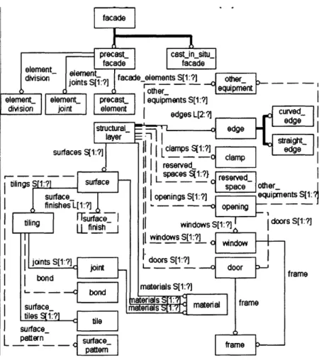
While optimization has often been intended as single-objective, i.e. with only one major objective being optimized, this document focuses on multi-objective optimization, and takes into account many of the aspects that are necessarily part of the design process (Figure 1) of such a complex object as an architectural fa~ade.
In fact, the very nature of skin design for buildings is a multidisciplinary one: fa~ades
Figure 1
-
The overall design procedure diagram of a f a ~ a d e facade%
I
11 I I1
precast-I
[csstin_shu_l
I
facadeI
other-l
edges L[2: ?I surfaces S[I:?] I I I II I I reserved- I I1
i
1
surface- finishes L[l:?] 2- I l finish I I I I l l,
(11
i
s ~ c e s ~ l : ? } j ~ l I space other-I1 1
openings S[l:?] -eqUimenb S U : ~ windows S[l:?] A doors S[l:?] windows S[l:?]I
jants S[l:?] doors S[l:?] joi.~1 I
L - - -I
bond-
,1
materials S[l:?]surface- materials aer'a's s['! S[ . material frame tiles ql:?]
tile
T
I I surface- U I I
must meet, beside structural safety, numerous architectural and technical requirements, such as transparency, sufficient light intake, minimal thermal loss, a limited cost of building materials, and manufacturing and installation constraints.
In the traditional design approach, many actors participate in different phases, each with diverse competencies and solutions to a particular aspect: the architect drafts the
overall formal composition of the fa~ade and coordinates the work of the technical teams; structural engineers design the supporting system
-
which in the case of a structural faqade is a very complex task due to the critical density of many technological systems in a very reduced portion of the building-,
HVAC engineers determine the material properties of the faqade according to thermal requirements, and lighting consultants ensure that a sufficient amount of light penetrates in the interiors, only to cite a few.In this sequential approach, due to the well-defined boundaries between disciplines, different competencies work on the design at different times, each one modifying the product of the previous one to achieve its objective.
Thus, the final solution is not always the optimal or the one that requires the least time to figure out. In fact, the overlapping of many decision-makers who act separately, and often times have conflicting goals, generates recurrent changes and unnecessary feedback loops in the design process. If all the requirements and partial objectives had been taken into account at an earlier stage, a more suitable and economic solution would have been found.
A multidisciplinary approach allows to gain information earlier and to retain design freedom longer, accommodating from the very first steps of the design process all the particular requirements coming from the many interacting disciplines (Figure 2).
10Wh
4
Cunceotual 100?40 Preliminary 1 00% Detailed 1 00%r Time into design process
Figure 2
-
Reorganization of design process in aeronautic industry to gain information earlier and to retain design freedom longerThe design solution is not envisioned a priori, and a very wide exploration of potential solutions is encouraged. Each solution is rated on the basis of multi-objective criteria operating simultaneously.
Thus, given a series of objectives, such as structural safety, thermal and lighting comfort, functional aptness, and reduced cost, via a "reverse design" procedure, the fittest solution (or a family of fit solutions) is determined.
P
increasingaJ due
To sequential design
AR*
Aspect Ratio
AR
Figure 3
-
Sequential vs Concurrent Design (design of an aircraft wing)It is easy to understand the advantages of optimization-driven, concurrent design (Figure 3) with respect to the traditional sequential approach that, due to the complexity of the design problem, envisions a very limited number of potential solutions, assesses their efficiency and checks for feasibility. The "optimality" of the solution heavily relies, in that case, on the experience of the designers and of the project coordinators.
However, multi-objective optimization is not a universal panacea. It is a procedure that requires tremendous computational resources, in the attempt to explore the highest number of potential design solutions. Design is ultimately a matter of sensibility and intuition. It is our strong belief that, in the choice of the initial design assumptions, as well as in the final assessment of the design solutions, critical sense and experience always constitute a precious and irreplaceable skill for every designer.
This document presents multidisciplinary optimization as a precious tool for the designer, and describes how it was used to undertake the design of a self-supporting building fa~ade.
1
.I
The
Problem
The design of a building structural fa~ade is a complex process that involves many disciplines and competencies.
The skin is a crucial, active site in the building, because it constitutes its interface with the exterior. It is meant to block or allow the flow of matter, such as rain, people or things, and energy, in the form of light, heat (or cold), and radiation, following a number of functional criteria. In the proposed case, the skin is also the supporting structure of the building.
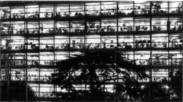
In addition, the fa~ade is the "face" and the "business card" of a building toward the exterior (Figure 4), and must therefore comply with aesthetic requirements and formal equilibrium (or dis-equilibrium).
In this study, a number of design aspects were considered of primary importance, and were consequently included in the optimization process:
1.1. 1 Architecture
A building can and often does succeed or fail in the public realm by nothing more than what it looks like.
Fa~ade design must be driven by interior results as much as exterior appearance; form, and skin decisions strongly influence lighting performance, cooling loads, and occupant comfort.
Figure 4
-
Transparency in architecture: the f a ~ a d e of the Fondation Cartier in Paris, by architect Jean NouvelIn the design of the faqade, a fundamental architectural requirement was taken into account: the need for the skin to be transparent at the height of the occupants' eyes, in order to allow a clear view on the exterior.
1
. I
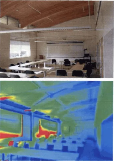
.2 LightingDaylighting is the use of light from the sun and sky to complement or replace electric light. Appropriate fenestration and lighting controls are commonly used to modulate daylight admittance and to reduce electric lighting, while meeting the occupants' lighting quality and quantity requirements (Figures 5 and 6). Daylighting can provide required ambient lighting for most operating hours.
In the design procedure presented in this study, the distribution of window and cladding in the f a ~ a d e determines the nature and the amount of daylight in the interior space.
Figure 5
-
Daylighting for a ClassroomFigure 6
-
Numerical illuminance analysis of the above classroom1
.I
. 3
Thermal
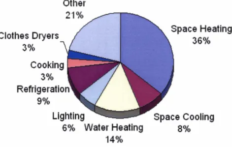
The skin thermal properties have a tremendous influence on heating and cooling loads, which account for 44% of the total consumption for a residential building in the U.S. (Figure 7).
A good design of cladding and insulating panels reduces peak loads and individual zone fluctuations. A smart fa~ade design can save operating and mechanical first costs, and reduce mechanical pace requirements.
Reducing cooling loads provides many benefits: smaller mechanical rooms and shafts yield more leasable space; smaller plenums allow higher ceilings or possibly additional
floors within building height allowance; and finally, smaller equipment is less visible on the roof and is easier to accommodate within normal floor-to-floor heights.
Residential bldgs enduse splits (1
995)
Other
21%
-
Space Heating
Clothes Dryers
3%
74
Cooking
3%
1
Lighting
Space
Cooling
6%
Water
Heating
8%14%
Figure 7
-
Energy consumption in residential buildings, end-use split1
.I
.4Structural
In a self-supporting fapde, the structure plays a fundamental role, and constitutes a critical aspect of the overall conceptual design.
Beside providing resistance and stability, with respect to both service and extreme loads, the structure has to be minimal, while meeting a number of requirements, such as the ease of connection to the floors and to the cladding, the need for architectural openings, the accommodation of thermal differential deformation.
In this study, the structure is considered a major issue from the point of view of the project feasibility.
In fact, from the perspective of a future further development and diffusion of CADICAM integrated technology, which will ease constructability of any irregular structural
geometries, and considering the reduced cost of materials, the cost of the structural system is not crucial.
As opposed to that, the need for a slender structure that can at the same time closely accommodate a complex skin geometry, often characterized by large openings, plays a major role in the overall design process.
1
.I
.5Economy
High-performance claddings and glazing cost more than their standard alternatives but may pay for themselves in four ways:
o reduced energy consumption,
o reduced first costs in mechanical equipment, o increased occupant productivity, and
o avoided future retrofit costs in added mechanical equipment or window fixes, due to commonly unanticipated occupant discomfort.
1.2
Definition of the design object
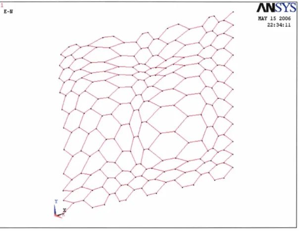
The fagade is a hexagonal grid, and each cell can either host a window or a cladding panel.
It is supported by a 2D, non-planar truss of steel pipes, connecting at the nodes in welded joints (Figure 8).
1.2.1
Geometry
The fagade is composed of hexagonal cells organized in a "beehive" pattern. The portion that this study focuses upon is a rectangle 5 m wide and 3 m high, and comprises 100 cells (1 0 rows x 10 columns).
The topology of the "beehive" never changes during the optimization process, i.e. no new cells can be generated and no cells can disappear, but distances between nodes can vary, and, consequently, also the areas of the cells are variable, as well as the lengths of the connecting segments and the amplitude of the angles.
Figure 8
-
The hexagonal grid of the structureDuring the optimization process, the nodes move, driven by the "need" for optimum performance: more light in the interior, less energy loss, increased structural efficiency, etc.
The nodes are allowed to move on the surface of the fapde, generating cells with very different areas and geometry, and can also move on the perpendicular direction,
causing the fapde to "bulge" outward or inward, depending on the requirements and on the constraints.
1.2.2
Materials
Each cell is characterized by a material variable, which can assume three states: transparent - corresponding to glass
-,
semi-transparent (shaded glass) and opaque (cladding panel).During the optimization process, the need for more light in the interior and for a lower heat loss through the skin forces the cells to turn transparent or opaque.
The goal of the optimization design process is to determine the spatial form of the faqade and the material that each cell is made of.
Chapter 2: The idea: using MSDO
The need to take into account all these aspects from the very earliest steps of the design procedure suggests adopting a performance-driven, integrated approach to the problem.
2.1
What
is
MSDO?
Multidisciplinary System Design Optimization (MSDO) focuses on the multi-objective optimization of complex systems, which can be broken down into a number of
elementary sub-systems. The solving procedure for a subsystem is often well-known, and is generally studied by a single traditional discipline (structural or mechanical engineering, architecture, etc.) (Figure 9)
It is a methodology for the design of systems where the interaction between several disciplines must be considered, and where the designer is free to significantly affect the system performance in more than one discipline.
Design Vector Si~nulation Model Objective Vector
r I r r l -. Discipline A ---. Discipline B
-
tI
,
Discipline C*
b L Methods Special Techniques Figure 9 -Multi-disciplinary System Design Optimization frameworkHowever, the interdisciplinary coupling inherent in MSDO tends to present additional challenges beyond those encountered in a single-discipline optimization. It increases computational burden and complexity, and creates organizational challenges for implementing the necessary coupling in software systems. This explains why MSDO is a relatively young discipline, whose expansion has been made possible by the
development of more powerful and versatile computing machines.
In addition, in MSDO of complex systems the organizational challenges become
formidable. The analysis codes for each discipline have to be made to interact with one another for the purpose of system analysis and system optimization, the kind and breadth of interaction being affected by the MOO formulation.
Decisions on the choice of design variables have profound effects on the coordination and data transfer between analysis codes and the optimization code, and on the degree of human interactions required.
2.2
History
From a historic perspective, the mathematical problem of multi-objective optimization had already been tackled in the field of Economics.
In 1881, King's College (London) and later Oxford Economics Professor F.Y. Edgeworth was the first to define an optimum for multi-criteria economic decision making.
He did so for the multi-utility problem within the context of two consumers, P and
rr:
"It is required to find a point (x,y,) such that in whatever direction we take an infinitely small step, P and rr do not increase together but that, while one increases, the other decreases. "
Paradoxically, it was a civil engineer who first developed the theory of multicriteria optimum if the field of Economics, which only after a century started being applied to engineering.
Vilfredo F. D. Pareto (Paris, 1848
-
Lausanne, 1923) was an Italian sociologist,economist and philosopher. After graduation from the University of Turin in 1870 with a degree in Civil Engineering, with a Thesis on 'The Fundamental Principles of
Equilibrium in Solid Bodies", he worked in Florence as a Civil Engineer from 1870-1 893. He took up the study of philosophy and politics and was one of the first to analyze economic problems with mathematical tools. In 1893, Pareto became the Chair of Political Economy at the University of Lausanne in Switzerland, where he creates his two most famous theories, regarding the Circulation of the Elites, and the so-called Pareto Optimum.
From his "Manuale di Economia Politicd':
"The optimum allocation of the resources of a society is not attained so long as it is possible to make at least one individual better off in his own estimation while keeping others as well off as before in their own estimation."
The arrival of MSDO in engineering sciences is strictly intertwined to the recent history of aeronautics.
Multidisciplinary System Design Optimization was introduced in Aeronautic Engineering, starting from the 70's. It initially was associated to disciplines such as aerodynamics, propulsion, structures, and controls, but in a second phase was also applied to lifecycle areas of manufacturability, supportability, and cost.
After the 'big slump" in world economy in the mid-seventies, due to the "oil crisis" (1 973), the major crisis of the airline industry and the end of the Apollo program led to a
reduction in the engineering workforce of around 25%. It was not anymore possible to "waste" enormous quantities of fuel and resources, and industrial designers were forced to look for higher-performance design procedures and methodologies. In the meantime, two major new events took place: the development of Computer Aided Design (CAD), which greatly contributed to the integration of informatics and automation in the design industry, and the procurement policy changes for airlines and the military.
In this panorama, the earlier quest for maximum performance was quickly superseded by the need for a "balance" among performance, life-cycle cost, reliability, and
maintainability.
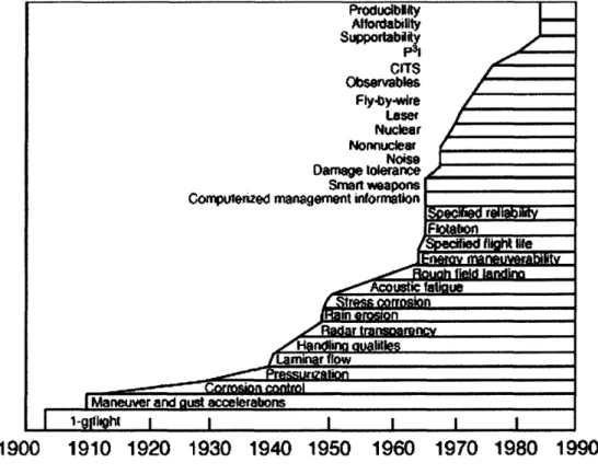
These new requirements, together with the exponentially-growing technological complexity of the aircrafts (figure lo), and with a harsher competition in the airline industry created a demand for an increased operational efficiency. MSDO was the off spring of these historical forces.
Figure 10
-
Design requirement growth for aerospace vehiclesSince 1990, the techniques have expanded to other industries. Globalization has resulted in more distributed, decentralized design teams. The high-performance
personal computer has largely replaced the centralized supercomputer and the Internet and local area networks have facilitated sharing of design information. Disciplinary design software has become very mature. In addition, many optimization algorithms, and in particular the population-based algorithms, have advanced significantly.
2.3 How does MSDO
work?
Given a system, or the object of the design, Multi-Objective Design Optimization involves the following phases:
o the selection of a set of variables to describe the design alternatives;
o the selection of a series of objectives (criteria), expressed in terms of the design variables, which are to be optimized;
o the determination of a set of constraints, expressed in terms of the design variables, which must be satisfied by any acceptable design;
o the determination of a set of values for the design variables, which optimize the objectives, while satisfying all the constraints.
Problem formulation is normally the most difficult part of the process. It comprises the selection of the design variables, constraints, objectives, and models of the disciplines. A further consideration is the strength and breadth of the interdisciplinary coupling in the problem.
2.3.2 Design variables
A
design variable is a numeric value that is controllable, from the point of view of the designer. For instance, the thickness of a structural member can be considered a design variable. Design variables can be continuous (such as a beam span), discrete (such as the number of beam supports), or Boolean (such as whether to use pretension or not in a concrete beam). Design problems with continuous variables are normally solved more easily. Design variables are often bounded, that is, they often have maximum and minimum values.Constraints
A constraint is a condition that must be satisfied in order for the design to be feasible. An example of a constraint in aircraft design is that the lift generated by a wing must be equal to the weight of the aircraft. In addition to physical laws, constraints can reflect resource limitations, user requirements, or bounds on the validity of the analysis models.
Constraints can be used explicitly by the solution algorithm or can be incorporated into the objective using Lagrange multipliers.
2.3.4
Objectives
An objective is a numerical value that is to be maximized or minimized. For example, a designer may wish to maximize profit or minimize weight. Many solution methods work only with single objectives. When using these methods, the designer normally weights the various objectives and sums them to form a single objective. Other methods allow multi-objective optimization, such as the calculation of a Pareto front (see
5 2.3.7).
2.3.5
Models
The designer must also choose models to relate the constraints and the objectives to the design variables. These models are dependent on the discipline involved. They may be empirical models, such as a regression analysis, theoretical models, such as from structural mechanics, or reduced-order models of either of these. In choosing the models the designer must trade off fidelity with analysis time.
The multidisciplinary nature of most design problems complicates model choice and implementation. Often, several iterations are necessary between the disciplines in order to find the values of the objectives and constraints.
2.3.6
Standard form
Once the design variables, constraints, objectives, and the relationships between them have been chosen, the problem can be expressed in the following form:
minimize J(x)
subject to: h(x) = 0 g(x) 0 x € X c 9 t n
where J is an objective vector, x is the vector of design variables, g is a vector of constraints, and h(x) and g(x) are vectors of lower and upper bounds on the design variables. Maximization problems can be converted to minimization problems by multiplying the objective by -1. Constraints can be reversed in a similar manner.
2.3.7
Mefhodo/ogy
There are two fundamental approaches to multi-objective optimization, the scalarization approach and the Pareto approach.
Scalarization reduces multiple objectives to a single combined objective.
Given a number of objective functions J1, J2,
. .
.,
Jz, a single, scalar function U of these functions is defined, and subsequently optimized.The problem is therefore reduced to a single-objective optimization:
Note that this approach necessarily includes preferences upfront, when the structure of the U function is designed.
The Pareto approach consists in determining the set of the non-dominated solutions, i.e. those vectors of solutions {J1, J2,
.
.
.,
JS such that:J: 2 J:
v
i and J: > J: for at least one iThese solutions are such that, if the system is optimized to that z-uple of J's, it is impossible to further increase one J while keeping all the other J's as high as before. With this approach, the preference is included a posteriori.
2.3.8
Problem solution (Scdlarization approach)
Scalarization approach was selected, due to the ease of implementation and to the possibility of expressing a preference on the importance of the single objectives.
The problem is normally solved using appropriate techniques from the field of
optimization. These include gradient-based algorithms, population-based algorithms, or others. Vety simple problems can sometimes be expressed linearly; in that case the techniques of linear programming are applicable.
Some of the traditional algorithms include:
Gradient-based methods: o Newton's method o Steepest descent o Conjugate gradient
o Sequential quadratic programming
Population-based methods:
o Genetic algorithms
o Particle swarm optimization
Other methods:
o Random search o Grid search
o Simulated annealing
Most of these techniques require large numbers of evaluations of the objectives and the constraints. The disciplinary models are often very complex and can take significant amounts of time for a single evaluation, and the solution can therefore be extremely time-consuming. Many of the optimization techniques are adaptable to parallel computing.
2.3.9
Genetic Algorithms
A genetic algorithm (GA) is a search technique used to find approximate solutions to optimization and search problems. Genetic algorithms are a particular class of evolutionary algorithms that use techniques inspired by evolutionary biology such as inheritance, mutation, natural selection, and recombination (or crossover).
A brief history and the basic concepts about Genetic Algorithms are provided in Appendix A.
Chapter 3: Design Optimization
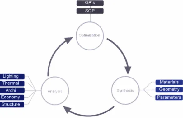
An analytical model of the design process was developed, following a disciplinary breakdown (Figure 1 1 ).
A set of suitable design variables was identified, and the aspects of design that were previously discussed (architecture, lighting, thermal, structural, economy) were separately analyzed by "satellite" modules.
Optimization
/"\
Figure 1 1 Working scheme of the optimization system
Each module returns an objective function, which a performance module rates via utility functions and collects into an overall utility objective.
Optimization is then run to maximize the overall objective, and the fittest design vector is returned.
3.1
Architecture
of
the
Model
The architecture of the model is composed of the initializing modules (Initialization and
Design Vector), the five evaluating modules (Lighting, Thermal, Architecture, Structures and Economy), the performance module (Performance), and the Optimizer (Figure 1 2). All the modules are described in the following paragraphs.
I*,.
..--..--
'.""" ---*-.--*.--.--IEconomy .- - 1
Figure 12
-
Complete architecture of the optimization system3.1.
I
Design Vector
3.1.I
.I
GeometryThere are 242 nodes, their positions being defined by three Cartesian coordinates (X, Y, and Z) in space, and by "deformed" coordinates on the skin (u, v). Due to the
constraints on the displacement of the nodes, the Jacobian of the transformation between the two sets of coordinates (X, Y) and (u, v) is always nonzero, i.e. the transformation is non-singular.
Given the computational complexity, however, only a subset of the nodes was chosen to describe the geometry of the skin. These points are called Control Points.
The displacement of each point on the grid is uniquely defined by the position of the Control Points.
There are 16 Control Point (four rows and four columns) plus another 16 on the borders, and the geometry is therefore fully described by 48 design variables (2 coordinates [u, v] per Control Point plus 1 coordinate for CP's on the border).
3.1
.I
.2
MaterialsEach cell can be made of glass, shaded glass, or opaque cladding. These materials correspond to three degrees of transparency (Figure 14).
The distribution of materials on the skin is therefore described by 100 discrete variables,
which can assume 3 states each.
Figure 14
-
Graphical representation of the materials Design VariablesAs a consequence, the design is controlled by a total of 148 variables.
3.1.2
Geometly
module
The geometry module, developed in CATIATM, is responsible for the construction of the skin geometry. Modelcenter passes to CATlA the coordinates of the Control Points, and CATlA calculates the positions of all nodes via parametric design. It also produces the measures of the cells areas, and all other geometric, parametrically-defined properties of the fa~ade. In addition, CATlA parametrically designs all the structural and non- structural fa~ade components, such as the shaders, the steel pipes, the joints, etc., and
Figure 15
-
A screenshot of a solution, from CATIA. Note the parameters on the left, which control the design 3.1.3lnitial~zafl'on
Module
For the initialization of the model, the calculation of the exterior illuminances for vertical
sky Exvk, horizontal sky E&k, and ground EWk for the given location and orientation, is
run solely once at the beginning of the optimization procedure. 3.1.4
Lighting
Module
This module (Figure 16) calculates the actual illuminance at 70% of the room depth, using the IESNA method, and based on four reference dates of the year.
The following calculations are performed:
o Look up the Coefficient of Utilization in a table embedded in an Excel file. The
table is implemented as an approximation function for better performance
(maximum error *lo%):
CUk = ( 0 . 3 6 2 - ~ ~ ~
+
- 5 . 9 8 . ~ ~ '+
33.1 -RW+
0.0253) * 0.01 07-RR-
1.49Calculate Illuminance
I
Room dimensions
-
I IlluminanceGlass total height
I
---
Chrck on min value,
Glass total width
Figure 16
-
Scheme of the Lighting module With: room-
depth RR = window-
height window - width RW = window-
heightCUk,, : Coefficients of Utilization for lighting calculation (sky, ground)
o Calculate the illuminance for each single cell
Where:
lux llluminance indoor at 70% of the room depth
lux llluminance outdoor (vertical, ground) % Light transmittance of the glazing
o Sum up the cells results in order to obtain an overall illuminance (ERO) o Check the constraint on minimum total illuminance
Ei70 2 300 IUX
Thermal
t
Figure 17
-
Scheme of the Thermal module ICell Materials
Cell areas C ~ a l c u l a t e Heat Transfer
I
Calculate Cooloing Loads[
I
Calculate Total EnergyI
The energy flows are calculated as follows: QH = (Utr Atr +Uop A,,) AT DDH
Qc = (Utr Atr +Uw A,) AT DDc
+
SHGSHFC
.
AtrEnergy Consurr and finally: Qtot = QH + QC Where: QH,C Utrlop Atrap DDHSC SHG SHGF Qtot
kwh/y1m2 Energy required for heating I cooling
w 1 m 2 ~ Coeff. for heat transmission (transp I opaque)
m2 Area (transparent I opaque)
dC Degree days for heating and cooling
w1m2ly Solar heat gain per one summer
YO
Portion passing through the chosen glazingkwh/y/m2 Total energy consumption
3.1.6
Architecture
The module (Figure 18) makes sure that the density of transparent cells increases toward the center of the fapde, for the occupants to have a view on the exterior.
Cell Materials
-
Zoning RatingFigure 18
-
Scheme of the Architecture moduleThe zone of preference for transparency is defined by a matrix with as many elements
as the cells are (1 0 x lo), whose values are higher where more transparency is needed.
Multiplying this preference matrix by the actual transparency distribution on the fa~ade, and summing up the terms, provides the rating for architecture.
where:
is the degree of transparency of cell i (l,2, or 3)
is the desired zoning preference for that cell.
3.1.7
Structure
The structural module (Figure 19) assesses the physical feasibility of the design. It is developed in AnsysTM 10.0, and is run in batch mode directly by Modelcenter.
Structure
Geometry
Qply vertical loads
Figure 19
-
Scheme of the Structure moduleThe input consists of the coordinates of all the nodes of the "beehive" grid.
From this set of points, Ansys creates the spatial grid of pipes connecting the nodes, sets the restraints on lateral nodes and applies the loads on top of the fapde. A static solution is then calculated and, based on the ratio stresslcapacity in the members, an overall rating is returned.
The choice of the structural system was a controversial issue, and ended in a trade-off between structural optimality and minimization of computational time.
Initially, a statically determinate 3D truss-shell was conceived, which was composed of
two connected parallel layers (grids) of members.
In this case, stability is ensured by the spatial structure, but the distance between the two layers heavily impacts on the thickness of the fagade and on the skin appearance from the interior.
A single-layer solution was by far preferable, but needed rigid connections between the members, i.e. welded joints rather than pins, to provide stability.
This solution allows a very thin skin, but presents some drawbacks, due to the
monolithic overall behavior of the structure, namely with respect to thermal differential deformation.
In addition, a major challenge concerning the optimization of a statically undetermined structure, such as a welded-joints 2D grid, consisted in the optimization of member sizing. In fact, given a determinate structure and a set of loads, it is immediate to calculate the forces distribution and the displacement of every member, regardless of size and material. As opposed to that, an undetermined structure cannot be solved without drawing upon its elastic (or more generally rheologic) properties.
Thus, in order to optimize an indeterminate structure, given a spatial geometry and a set of loads, it is necessary to adopt a recursive approach, iterating until convergence is achieved, because after changing the size of members the stress distribution has to be calculated anew.
As it can be imagined, setting up an internal, nested structural optimization loop within the overall multidisciplinary optimization process required humongous computational effort, and consequently a very long time, that was not available.
A trade-off was then achieved: the structural module works as a checker rather than as an optimizer: it receives the geometry and the loads, and checks for structural
resistance given a constant size of members. All the pipes have a constant diameter, regardless of length.
Ansys calculates the stresses in the members and returns to the optimizer a rating function, which "grades" the input geometric pattern from a structural point of view.
In analytical terms, the rating function has the following form:
Where:
O , i MPa is the maximum stress (absolute value) in member i
N is the number of elements f, MPa is the yield stress of steel
It could be argued that, following this procedure, the design solution that eventually is produced by the optimization process is inherently vitiated by an unintelligent use of material, since the diameter of the pipes is constant. In addition, this study does not approach member buckling, which would have required a subroutine solving the associated eigenvalue problem.
However, beside the benefits coming from shorter computational time, this solution respects and achieves the goal of the structural module, i.e. it provides a balancing counterweight that limits the maximum size of cells. In fact, by pushing the value of the stress toward the yield limit (since the size of the members is constant, the module indirectly sets an upper bound on their maximum length.
In the framework of this study, therefore, structural design was not developed beyond the stage of a feasibility study, both due to the central interest in the multidisciplinary aspect of design and because of the heavy computational constraints.
3.1.8
Economy
The economy module (Figure 20) calculates the cost of glass and cladding materials associated with the design vector.
The cost is linearly evaluated with respect to areas and depends on the type of materials.
Material Area
Economy
Cell Material
1
1
Cost of Materials
(
Linear calculation on areas/
3.1.9
Performance
Because of the multi-objective nature of the architectural design of a fapde, each of our modules produces some functions (total illuminance, energy required for heating and cooling, etc.. .).
Each single objective Ji is then "filtered" through a utility function Ui, that assigns a low
score to an undesirable value of J and a high score to a desirable one (0 5 U 5 1).
The Utility Functions have the form shown in Figure 21 :
Figure 21
-
Structure of the Utility FunctionsThe Utility Functions are scaled in such a way that an unacceptable performance has a utility rating less than 0.1, while an excellent performance is rated more than 0.9.
A performance is considered Unacceptable, Acceptable, Good or Excellent with respect to the optimum value that the output can assume, as shown in Table 1.
An overall objective function U takes into account all the multi-objective particular utilities Ui. The U function has the following form:
where wl, w*, w3, w4, w5 are weighting coefficients that depend on the importance of
Table 1
-
Threshold values for the utility functionsMax
This overall utility function reflects the trade-off between sufficient natural lighting in a Thermal
(Total Energy Min 10; 701
Consumption)
Lighting
(Illuminance) Max
[O;
20001 300room, the energy balance due to wolinglheating of the faqade, the intent to have
Architecture (Match with zoning preference) Structure (Rating function)
windows in view height, the requirement for structural safety, and limited cost.
3.1.10 OpO'rn~zer
The central optimizer is the "brain" of the system: it is charged of coordinating all the
"satellite" modules
-
by directing the input and output flows of variables-,
of checking the constraints, and running the solving algorithm.1 3.1
.I
0.1 A note on constraints Economy (T1
Min1
[o;
1500]1
10001
300 -- otal cost) -- --There are several types of constraints:
Firstly, each Control Point must lie in a specific region, delimited by red lines in Figure 22. Each red line is obtained by offsetting the corresponding gray line by an amount d.
[O;
1.11[O;
1.11-
0 0.85 0.85-
These constraints prevent each quadrilateral region from assuming a non-convex shape,
a fact that would create computational problems and would result in unaesthetic design.
Figure 22
-
Graphical representation of the geometric constraintsThis kind of constraint is defined by the following equations (in the case of quadrant NE):
Where:
UC, VC are the coordinate of the point subject to the constraint
UE,S,W.N, and VE.S,W,N are the coordinate of the adjacent points that lies
respectively to the East, South, West and North of point C
Thus, there are 64 constraints of the first type (geometric constraints [GC] in the
following), considering the Control Points on the borders. Each of these constraints only apply to the correspondent geometric design variable.
Secondly, a constraint on the overall illuminance sets:
providing a lower bound for the amount of light measured at 70% of the room depth. Note that this illuminance constraint [IC] affects all the design variables with different sensitivity.
3.2 Software & Hardware Tools
The software architecture closely reflects the breakdown structure of the problem into disciplines.
A central Optimizer is linked to CATIA, which produces and updates the geometry of the fa~ade, and to the "satellites" Modules, one per discipline (lighting, thermal, etc.. .).
ModelCenter 6.1 TM, from Phoenix Integration Software, Inc., was chosen as the central Optimizer.
It is a very versatile and young program, it can easily interface with most CAD software, spreadsheets and programming languages, and has a very user-friendly interface. Communication between the Optimizer and the Modules is ensured by the wrappers. These pieces of code translate variable formats and manage the flow of input/output files that written and read by the communicating programs.
The Lighting, Thermal and Economy Modules were programmed on MS Excel XPTM, for which ModelCenter has a built-in integration module.
The Structural Module, as was pointed out in
5
3.1.7, was built in AnsysTM 10.0, from Ansys, Inc., a very powerful FE modeler, solver and post-processor.The computational burden generated by such an onerous process as the multi-objective optimization of more than a hundred variables, subject to hundreds of constraints, and the use of Genetic Algorithms for the solution of the problem, required the use of a bi- 3.2 GHz processor machine in order to cut down computational time.
3.3 Multi-objective Optimization
The Scalarization approach
(5
2.3.7) was chosen, due to the nature of the objective functions.3.3.1
Optimization Algorithm
Genetic Algorithms were chosen because they have experimentally been proven to be robust in their application to many search problems, and are ideally suited for design problems with discrete design variables.
Because they do not require objective or constraint derivative information, they are able to effectively search non-linear and noisy design spaces.
Compared to traditional gradient-based optimizers, genetic optimizers are more likely to find the overall best (globally optimal) design.
3.3.2
Genetic AlgonThm parameters
When using heuristic techniques like the GA's, a fundamental part of the solving procedure consists in tuning the algorithm parameters, whose values can often determine the success or failure of the analysis.
The GA's parameters that were controlled in this study are listed hereafter:
General: Population size Selection scheme Preserved designs 30 Multiple Elitism 13 Convergence:
Convergence method Maximum Number of Generations Maximum No. of generations 50
Genetic operators:
On the basis of the experiments that were carried out, some recurring effects related to the values of these parameters could be observed.
The population size is the number of individuals per generation. In general, the larger the population size, the longer the optimization process will run because of the
increased number of component runs required. Thus, the population size was initially set as small as possible and then slowly increased when the optimizer could not converge consistently to an acceptable design.
The genetic algorithm's selection scheme is the mechanism that determines which designs from the parent population and newly created child population will be chosen to make up the next generation of designs. The selection scheme ensures that the
optimization procedure continually progresses towards an optimal solution by allowing the best design(s) in each generation survive in the next generation.
The "Multiple Elitism Selection" selection scheme was retained all throughout the optimization procedure. This selection method is more effective for problems like the proposed one, for which the search space has multiple global optimum points or for problems where the global optimum is surrounded by many local optimum points.
The number of preserved designs (Np) specifies the number of best designs from the combined population that are passed on to the next generation, and is used to control the selection pressure of the genetic algorithm.
As this number increases, though, the number of new designs entering the population decreases, causing the genetic search to become more localized. Thus, using large values of Np prevents the GA's from successfully exploring the design space and may cause them to get trapped in a local optimum area of the search space. Therefore, the value of Np was kept relatively small (13) compared to the population size, so that a number of good designs could be tracked while maintaining a sufficient influx of new individuals to continue searching other areas of the design space effectively.
The maximum number of generations is an important parameter, because it sets the limit of the optimization process. Generally, the higher the number of generations, the more refined the search, because each generation is likely to refine the results provided by the previous one. However, each generation also requires additional CPU time, and a trade-off between accuracy and time consumption must consequently be agreed upon. The selected final number of generations was 50.
Mufation probability represents the probability that a mutation will occur in a chromosome, and is one of the most effective GA operator. Again, the value must respect a trade-off between two opposite forces: a certain amount of mutation probability is necessary to provide chromosomal diversity in the population, but an excessive rate might lead to instability in the algorithm, and to the loss of important genetic information. The final value of 6% appeared to be the best trade-off.
Chapter
4:
Results
4.1
Final results
The Genetic Algorithms were terminated after 50 generations, and the best recorded results were collected.
The optimization process converged to the solution that corresponds to the following design vector:
Figure 23 shows the distribution of materials corresponding to the final solution, while, in Figure 24, a render illustrates the final design of the fapde.
Figure 24
-
Render of final designA number of considerations can be drawn form these results:
o The solution effectively shows a particular geometrical and material pattern:
The cells at the center of the fagade correctly enlarge, and shrink as the distance from the center increases.
In addition, in the center of the fagade a complete region turned to glass, a consequence of the Architectural Module action.
Away from the center the density of semi-transparent and opaque material grows higher, a sign that a trade-off was reached between lighting and architectural requirements on one side, and thermal requirements on the other. To compensate a higher density of transparent cells in the center of
the skin, which allow for a more abundant light intake, the cells close to
'1
o This configuration slowly becomes evident as the number of generations grows. The central pattern of transparent cells develops from an early embryo, to fully occupy the whole central region of the skin.
o The distribution of the semi-transparent and opaque cells does not seem to
follow a particular scheme. It was not possible to understand if a distinguishable pattern might have been achieved after more generations. In any case, the slow progression of the overall objective function toward the end of the process suggests that any further variation in the design vector cannot generate a substantial change in the objective. However, it is important to note that, like for all heuristic techniques, the convergence of the GA's cannot be mathematically proven.
4.2 Diachronic evolution
The evolution of the design all along the generations of the GA's can be mapped by analyzing previous solutions.
Five solutions were chosen, evenly spaced in "time".
The graphical rendering of the solutions is a helpful tool to visualize the formation of geometric trends and patterns in materials distribution.
The graph in Figure 25 plots the improvement of the objective function against the number of generations. Figures 26 show the distribution of materials and the geometry corresponding to the chosen
solutions.
OBJECTIVE FUNCTION EVOLtlT1ON HISTORY
Run = 001 ...
...
Run = 020I
i
I
i
Run =250 Run = 312 Run = 435Chapter
Conclusions
Multi-disciplinary System Design Optimization was used to drive the design of a building structural faqade.
The optimization system shapes the geometry of the hexagonal base-grid of the fawde, and decides the materials in each cell of the grid.
The design process was analyzed and fragmented into several disciplines. A multi-objective optimization model was developed, encompassing a number of analysis Modules, which comprises:
o a Lighting Module, evaluating the illuminance in the interior,
o a Thermal Module, capable of calculating the cooling loads corresponding to the skin configuration,
o an Architectural Module, charged of turning to transparent the central cells, due
to view requirements,
o a Structural Module, which rates the structural efficiency of the design,
o an Economy Module, in order to calculate the cost of materials (cladding, glass).
A scalarization approach to MDO, via utility functions, was followed, and the overall objective function was optimized using Genetic Algorithms.
The fittest design solution, coherently with the requirements expressed by the Analysis Modules, shows a clearly distinguishable geometric pattern. In particular, the cells located at the center of the faqade tend to enlarge and to turn transparent, to allow a clear view of the occupants on the exterior (as suggested by the Architectural Module), while the cells close to the boundaries turn opaque and shrink, to counteract the
5.1
Openings
The study confirmed that MDSO is an interesting tool for design of complex systems, being particularly valuable when many disciplines concur in the design procedure.
Future research should definitely approach the problem of constructabi/ity, that was omitted in this study.
In fact, an uncontrolled optimization-driven design tends to generate a non-modular product, whose components do not follow any symmetry or geometric rule.
It follows that, from the point of view of cost, the design is often unfeasible.
The future development of CAD/CAM integrated technology should provide the designer a larger freedom, but it is undeniable that the cost of a product is dramatically cut down by some degree of modularity or symmetry of its components.
A "constructability module" would, therefore, penalize or set constraints on "non- constructable" solutions.
Also, a potential field of exploration concerns the extension of MSDO-driven design to larger, more complex objects, such as a complete building skin, or to a building itself. Some concerns arise, though, namely due to the computational burden that such an analysis would imply.
However, many techniques are being explored in recent literature, about how to define "smarter" design variables, or to develop more efficient system architectures.
Besides, it must be pointed out that the computational capacity of both single machines and of "diffuse" computing units is constantly increasing, permitting the analysis of more and more articulated and complex designs.
Appendix A: Genetic
Algorithms
Genetic algorithms are typically implemented as a computer simulation in which a population of abstract representations (called chromosomes) of candidate solutions (called individuals) to an optimization problem evolves toward better solutions. Traditionally, solutions are represented in binary as strings of 0s and 1 s, but different encodings are also possible. The evolution starts from a
population of completely random individuals and happens in generations. In each generation, the fitness of the whole population is evaluated, multiple individuals are stochastically selected from the current population (based on their fitness), modified (mutated or recombined) to form a new population, which becomes current in the next iteration of the algorithm.
A.2
History
Genetic algorithms originated from the studies of cellular automata, conducted by John Holland and his colleagues at the University of Michigan. Research in GAS remained largely theoretical until the mid-1 9809, when The First International Conference on Genetic Algorithms was held at The University of Illinois. As academic interest grew, the dramatic increase in desktop computational power allowed for practical application of the new technique. In 1989, The New York Times writer John Markoff wrote about Evolver, the first commercially available desktop genetic algorithm. Custom computer applications began to emerge in a wide variety of fields, and these algorithms are now used by a majority of Fortune 500 companies to solve difficult scheduling, data fitting, trend spotting and
budgeting problems, and virtually any other type of combinatorial optimization problem.
A.3
Operation
of
a GA
Two elements are required for any problem before a genetic algorithm can be used to search for a solution: First, there must be a method of representing a solution in a manner that can be manipulated by the algorithm. Traditionally, a solution can be represented by a string of bits, numbers, characters or by a special struct. Second, there must be some method of measuring the quality of any proposed solution, using a fitness function.
A.4
Initialization
Initially many individual solutions are randomly generated to form an initial population. The population size depends on the nature of the problem, but typically contains several hundreds or thousands of possible solutions.
Traditionally, the population is generated randomly, covering the entire range of possible solutions (the search space). Occasionally, as in the present study, the solutions may be "seeded" in areas where optimal solutions are likely to be found.
A.5
Selection
During each successive epoch, a proportion of the existing population is selected to breed a new generation. Individual solutions are selected through a fitness- based process, where fitter solutions (as measured by a fitness function) are typically more likely to be selected. Certain selection methods rate the fitness of each solution and preferentially select the best solutions. Other methods rate only a random sample of the population, as this process may be very time- consuming.
Most functions are stochastic and designed so that a small proportion of less fit solutions are selected. This helps keep the diversity of the population large, preventing premature convergence on poor solutions. Popular and well-studied selection methods include roulette wheel selection and tournament selection.
A.6
Reproduction
The next step is to generate a second generation population of solutions from those selected through genetic operators: crossover (or recombination), and mutation.
For each new solution to be produced, a pair of "parent' solutions is selected for breeding from the pool selected previously. By producing a "child" solution using the above methods of crossover and mutation, a new solution is created which typically shares many of the characteristics of its "parents". New parents are selected for each child, and the process continues until a new population of solutions of appropriate size is generated.
These processes ultimately result in the next generation population of
chromosomes that is different from the initial generation. Generally the average fitness will have increased by this procedure for the population, since only the best organisms from the first generation are selected for breeding, along with a small proportion of less fit solutions, for reasons already mentioned above.
A.7
Termination
This generational process is repeated until a termination condition has been reached. Common terminating conditions are:
o a solution is found that satisfies minimum criteria; o fixed number of generations reached;
o allocated budget (computation timelmoney) reached;
o the highest ranking solution's fitness is reaching or has reached a plateau such that successive iterations no longer produce better results;
o manual inspection;
References
Papalambros, Panos Y., and Wilde, Douglass J.. Princi~les of O~timal Desian. Cambridge: Cambridge University Press, 2000.
Dulikravich, G.S., Dennis, B.H., Martin, T.J., and Egorov, I.N.. Multi-Disci~linarv Analvsis and Desian O~timization. Invited Lecture, Mini-Symposium on Inverse Problems
- State of the Art and Future Trends, XXlV Brazilian Congress on
Applied and Computational Mathematics, Sept. 10-1 3,2001, Belo Horizonte, Brazil.Kodiyalam, S., and Sobieszczanski-Sobieski, J.. "Multidisciplinary Design Optimization
-
Some Formal Methods, Framework Requirements, and Application to Vehicle Design."c http://www.sgi.com/industries/manufacturin~mdo/pdf/mdo~methods.pdf~ (1 1 May 2006)
Sobieszczanski-Sobieski, J., and Haftka, R.T.. "Multidisciplinary Aerospace Design Optimization: Survey of Recent Developments".
c http://www.emse.f r/-leriche/MDOAFM/MDO-sobieski-haftka96,pdf> (1 1 May 2006)
O'Connor, J., Lee, E., Rubinstein, F., and Selkowitz, S.. Tips for Davliahtina with Windows. Lawrence Berkeley National Laboratory,
chttp://windows.lbl.gov/pub/designguide/dlg.pdf~ (1 1 May 2006)
Wikipedia.org, entry on "Multidisciplinary design optimization"
~http://en.wikipedia.or~wikilMultidisciplina~~design~optimization~ (1 1 May 2006)
De Weck, O., and Willcox, K.. Lectures for the Course of "Multidisciplinary System Design Optimization (MSDO)" (MIT Course 16.888/ESD.77, Spring Term 2006)