The Design of a Frame for an All Terrain, Lever
Propelled Wheelchair
by
John Michael Walton
Submitted to the Department of Mechanical Engineering
in partial fulfillment of the requirements for the degree of
Bachelor of Science in Mechanical Engineering
at the
MASSACHUSETTS INSTITUTE OF TECHNOLOGY
ARCHIVES
~MASSACHSEThr TSi
OCT
2
0 2011
L A
June 2011
@ John Michael Walton, MMXI. All right reserved.
The author hereby grants to MIT permission to reproduce and
distribute publicly paper and electronic copies of this thesis documents
in whole or in part.
Author ...
rtmentf-eihjanical Engineering
May 6, 2011
Certified by.
C let) Daniel D. FreyAssociate Professor of Me anical Engineering
The Design of an All Terrain Lever Powered
Wheelchair Frame
by
John Michael Walton
Submitted to the Department of Mechanical Engineering on May 6, 2011, in partial fulfillment of the
requirements for the degree of
Bachelor of Science in Mechanical Engineering
Abstract
This thesis outlines the process of designing a frame for the Leveraged Freedom Chair (LFC) Prime, an all-terrain levered powered wheelchair designed to improve the mobility of disabled individuals. This design allows for a system of two hand lever propulsion, turning, and braking that uses different hand grasp and gross movement patterns than those of a conventional wheelchair making it more efficient for a variety of functional mobility applications. The LFC Prime uses the fundamental design elements of the existing LFC design that has been developed for applications in third world countries. With the goal of manufacturing this product in the United States, a greater array of design possibilities become feasible due to the availability of higher performance materials and bicycle parts that would greatly enhance its performance. Therefore the LFC Prime wheelchair has the opportunity to make an impact in improving the mobility independence of a variety of disabled individuals in the US and other developed countries allowing them to adventure into all-terrain environments.
Thesis Supervisor: Daniel D. Frey
Acknowledgments
I would like to acknowledge Amos Winter, Daniel Frey, and Benjamin Judge for their guidance during the writing and design process.
Contents
1 Introduction 2 Design Constraints
2.1 User and Environmental Constraints 2.1.1 User Constraints
2.1.2 Indoor Environmental Constraints 2.1.3 Outdoor Environmental Constraints 2.2 Frame Performance Constraints
2.2.1 Weight
2.2.2 Transportability 2.2.3 Cost
2.2.4 Suspension
2.2.5 Three vs. Four Wheels 2.3 Design Constraints Conclusion 3 Frame Design 3.1 Frame Geometry 3.1.1 Suspension 3.2 Material Selection 3.4 Performance Verification 4 Conclusion
Chapter 1
Introduction
The intent of the Leverage Freedom Chair (LFC) is to improve the mobility of people with disabilities in developing countries. The primary benefits of the LFC arise from the versatility of the human ergonomics of the lever mechanisms. Typically
wheelchair users input their energy into the wheelchair through push rims located around the circumference of both drive wheels. The fundamental mechanics of the
LFC allows the user to shift their hand placement up and down levers allowing them to dynamically optimize the mechanical advantage for the environment. This can be seen in Figure 1.
OFF-ROAD NAVIGATION
LONG DISTANCE SPEED
Figure 1: Variable mechanical advantage drivetrain
From coverage of the LFC project in popular media such as "A Smoother Wheelchair Ride" on CNC and "MIT's levered wheelchair extends freedom to Third World" in The Boston Globe, wheelchair users in the US have expressed the desire for a
developed world version of the wheelchair, which is called the LFC Prime. The LFC Prime uses the same drivetrain design as the developing country chair, whereby the user adjusts hand placement on the levers to dynamically optimize the gear ratio for the environment. The principal feature differences between the two chairs are the
addition of suspension for comfort and a folding frame for transportability. This thesis is focuses on decisions, analysis, and justifications behind the design of the LFC Prime's frame.
Chapter 2
Design Constraints
The initial step of designing the frame of the Leverage Freedom Wheelchair was to determine the design constraints. First, the frame is dimensionally constrained by user and environmental factors. Second, the frame is constrained by the
performance that is required for the LFC Prime to be reliable, safe, and transportable.
2.1 User and Environmental Constraints
The dimensions of the user will constrain the minimum size of the LFC Prime while the environmental factors will constrain the maximum size. In other words, the wheelchair must be large enough to appropriately fit a user while must be small enough to navigate through environmental obstacles such as doorways or an outdoor path. Therefore there is an equilibrium that must be found to optimally size the LFC Prime for its intended users in its intended environment.
2.1.1 User Constraints
A wheelchair must be sized to the user. This would result in a wheelchair with an optimal performance of strength, weight, and comfort. The LFC Prime will be mass-produced therefore the design must account for variations of user sizes. Average dimensions can be used that will theoretically allow for 50% and 99% of all Americans to appropriately fit in the LFC Prime. (Dreyfus 2001) A critical
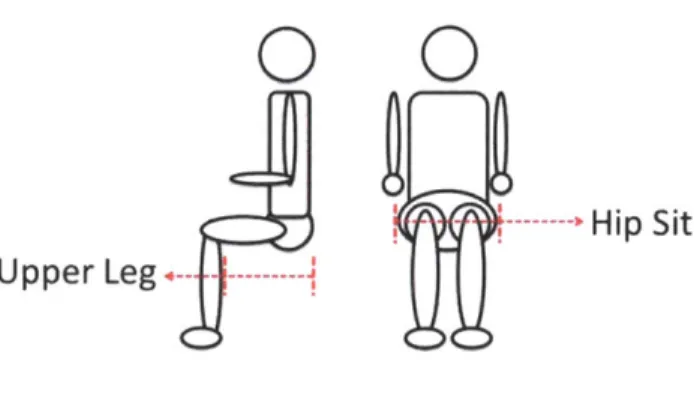
dimension is the seat width and length, which is defined by the user's hip width and upper leg length when sitting down. These dimensions are represented in Fig. 2.
Hip Sit Upper Leg
Figure 2: Shows the width of a human's hips when sitting down (hip sit) and the distance between the back of the calf and lower back (upper leg).
These dimensions can be seen in Table 1 below. Both male and female dimensions
are listed for 50th % and 99th % percentile.
50th % (inches) 99th % (inches)
Male Hip Sit 14.2 16.9
Female Hip Sit 14.6 16.8
Male Upper Leg 19.7 21.6
Female Upper Leg 19.2 21.1
Table 1: Hip sit and upper leg dimensions for male and females for 50 % and 99* % of the world's
population.
For this model the LFC Prime will be based on the 50th% and the future production model will include the 99th%. The width of the seat will be 14.6 inches and the length will be less than or equal to 19.2 inches.
2.1.2 Indoor Environmental Constraints
To be full functionality in an indoor environment, the LFC Prime must be capable of overcoming obstacles such as passing through doorways, navigating in public bathrooms, or turning around in hallways. Standard doorways are 32" wide and hallways are 60" wide according to ADA Accessibility Guidelines for Buildings and Facilities regulations. (ADA 2002) From this the width must be less than 36" and the turning radius of the wheelchair must be less than 30". To give insight, the standard width of a medical wheelchair is 26". (Dreyfuss 2001) Additionally, Table 2 shows the competitors overall dimensions.
Width (in) Length (in)
Sunrise Quickie Q7 24 35
Top End Crossfi re AT 30 39
Trekinetic K-2 31-35 39
Top End XLT Pro 26 72
Renegade Leverchair 30 40
Rota RoChair 24 40
MTNTrike Mk3 30 45
Invacare Power Offroad 23 36.5 Table 2: Dimensions of the LFC Prime's competitors (judge 2011)
From this data, the overall chair width (from the outside of one rear wheel to the other) should be around 24 inches. For indoor use it's optimal to reduce the width as much as possible, though for stability in outdoor conditions it's beneficial to have a wider width for stability.
2.1.3 Outdoor Environmental Constraints
For full functionality in an outdoor environment the LFC Prime must be capable of overcoming obstacles such as climbing a hill, rolling over rocks/bumps, and moving on a surface with a steep grade. The important dimensions while considering outdoor factors are the front and rear wheel diameter, width, and height.
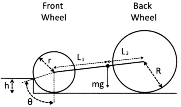
In off-road conditions, it's important to understand the limitations that the tires give to the user. In this case, the performance is defined by the height of an obstacle that a user can drive over. Note that the user cannot transfer his or her weight in this analysis and simply is modeled as a motor with a specific output. The theoretical model is setup as shown in Figure 3.
Front Back
Wheel Wheel
L -2 Sr
L---6 --
-Figure 3: Performance analysis setup for climbing obstacles of height h
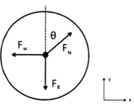
To simplify the model, the front wheel is isolated and analyzed separately as shown in Figure 4.
FW F
Fg
&. F
Figure 4: Free body diagram of the front wheel
Where F, is the force due to gravity, FN is the normal force due to the obstacle, and
F, is the force that the user's torque projects on the front tire. A set of simple
equations can be created when summing the forces in the x and y-axis.
-Fg
+ FNcos(6)=O (1)-F, + FNsin(O) =0 (2)
It is assumed that the wheel is only touching the obstacle and not the ground. This is done because then the model calculates the theoretical maximum force needed from the user to overcome the obstacle. The force due to gravity (F,) is found to equal Equation 3 as the weight is disperse over both wheels and the center of gravity isn't directly in the center of the LFC Prime. Where L and L2 are
respectively the length between the front wheel and the center of gravity and the length between the center of gravity and the back wheel, m is the mass of the LFC Prime and the rider, and g is the acceleration of gravity.
Fg mg (3) (1+-)
L2
With the force on the wheel (F,) and the radius of the rear wheel (R), the torque can be solved for by using Equation 4.
T = FR (4)
With equations 1-4, the torque can be solved with
T= LmgR (5)
(1+ -)cos(6)
L2
Note that 6 is a function of the height of the obstacle (h) and the radius of the front wheel (r).
6 = cos-1(r - h (6)
r
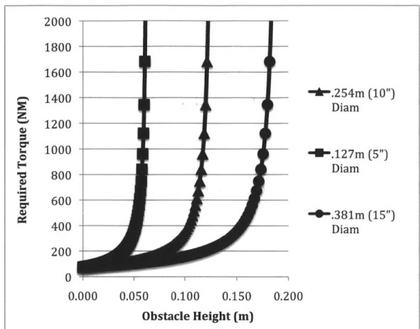
Three radii were chosen for the front wheel: 5", 10", and 15". For each radius, the required torque needed to overcome an obstacle with height (h) was found. This can be seen in Figure 5.
2000 1800 1400 - _""-.254m (10") Diam 1200 1000 .g...127m (5") Diam C 800 D ." 600 "'-"-.381m (15") 400 Diam 200 0 0.000 0.050 0.100 0.150 0.200 Obstacle Height (m)
Figure 5: Shows the relationship between obstacle height and the required torque applied by the user to successfully drive over it.
From Equation 5 and Figure 5, it can be determined that the curve is identical for all
three wheels except that the torque asymptotes at their respect radius. From this it can be concluded that increasing the wheel radius (r) has a linear relationship with the required torque (T) if the performance is constant.
The maximum torque that a human can apply using the LFC Prime drive train, which
has a 28:18 gear ratio, is 145 Nm. (Winter 2009) From this is can be concluded that
the largest obstacle for a given radius is:
hma =.48r (7)
This analysis is fairly limited in that it only models a static situation, though intuition about how the performance changes depending on the front wheel diameter can be gained. A 9-inch front wheel, carried from the initial LFC design, will theoretically result in a user being able to overcome an obstacle of 4.5 inches.
2.2 Frame Performance Constraints
As the LFC Prime is being designed for off-road capability, it's required that the level of performance of the frame must be capable of enduring various performance tests such as collisions at high speeds, falls and drops, and repeated high loads. For the performance analysis 100kg is used as the total mass of the LFC Prime and user. Additionally, it is desired that the frame be designed to withstand static loads with a factor of safety of 6.
2.2.1 Weight
The weight of the LFC Prime is an extremely important characteristic that will determine the success of the product as consumers commonly compare weight when determining what mobility aid to purchase as well as a lighter chair will result
in lower inertial loads and will be easier to load into a car. When comparing
competitor products it's becomes apparent that the LFC Prime doesn't exceed 30lbs to be competitive. As you can see in the Table 3, having a weight under 30lbs will provide a market as well as an obvious performance advantage over most chairs.
Weight (Ibs) Sunrise Quickie Q7 18
Top End Crossfire A T 30
Trekinetic K-2 25
Top End XLT Pro 30
Renegade Leverchair 50
Rota RoChair 45
MTNTrike Mk3 45
Invacare Power Offroad 175 Table 3: The weight of the LFC Prime's competitors (Judge 2011)
2.2.2 Transportability
For a user to conveniently transport and store the LFC Prime, it must have the functionality of reducing its size to fit into spaces such as automobile trunks or closets. A small size trunk is on average 14 cubic feet. Therefore the LFC Prime must have a simple mechanism that will compact its maximum dimensions as well as the functionality of quickly removing the wheels. It is important to note that the user is physically impaired, so any adjustment or folding operation must be
simplistic and accessible.
2.2.3 Cost
As with any consumer product, the cost to manufacture the LFC Prime is extremely important to its success. Much of the cost is associated with the hardware such as the wheels, sprockets, chain, and even screws and bolts. These costs, at the early stage of design are fixed, as we are purchasing these items from bicycle and
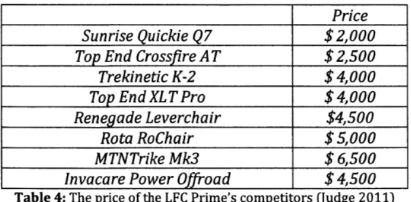
hardware venders. The optimization of the remaining parts such as the frame and seat are necessary to reduce the manufacturing cost as much as possible. In Table 4, the LFC Prime's competitor's prices are listed.
Price Sunrise Quickie Q7 $2,000 Top End Crossfire AT $2,500
Trekinetic K-2 $ 4,000 Top End XL T Pro $4,000 Renegade Leverchair $4,500
Rota RoChair $5,000
MTNTrike Mk3 $6,500
Invacare Power Offroad $4,500
Table 4: The price of the LFC Prime's competitors (Judge 2011)
The target price for the LFC Prime is $1000, as to fit in a yet unfilled market niche. (Judge 2011)
2.2.4 Suspension
Suspension, though not necessary, has potential to benefit the LFC Prime. It would result in more comfort for the user, which is even more important for this product than standard wheelchairs as it is designed for off-road applications. Furthermore, suspension could potentially increase the aesthetics of the product that would give more incentive to consumers to purchase it. In contrast, it would add to the
complexity of the design and result in a higher cost and weight.
A possible avenue that could combine the transportability and suspension design modules is use the degrees of freedom of the suspension as a way to fold the chair. Disconnecting or adjusting the suspension could allow for this functionality.
2.2.5 Three vs. Four Wheels
Typical wheelchairs have four wheels. Two smaller wheels are generally located in the front and two larger drive wheels are located in the rear. Some wheelchairs have a three-wheel design, which consists of the two larger drive wheels and a third smaller wheel in the front or rear. Both designs have their benefits that should be compared for this application.
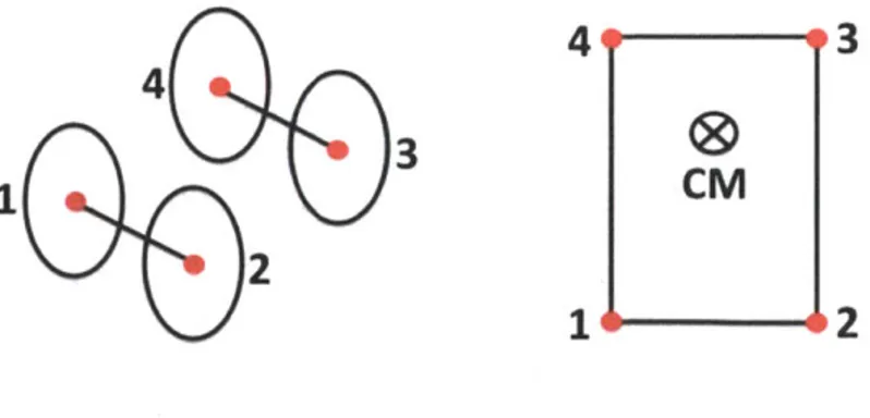
For a four-wheel design, there would be four points of contact typically in a rectangular orientation, assuming the group is perfectly flat. This can be seen in Figure 6.
4
9-93
CM
1
---
-
2
Figure 6: The stability of a four-wheel design
4
10
For the device to be stable, the center of mass (CM) should be in the center of the rectangle. If the center of mass is located outside the geometry (tipping lines) created by the points of contact then the device is unstable. A three-wheel design can be seen in Figure 7.
4 3 3--2 CM
iQi
1Figure 7: The stability of a three-wheel design
The distance between the center of mass (CM) and the tipping line (segments 1-4) and the distance between the center of mass and the ground determines the stability. To optimize stability it's necessary to maximize the distance between the CM and tipping line and minimize the distance between the CM and the ground. For this analysis, it can be assumed that the distance between the CM and the ground is equal in both chair designs as well as the length of both configurations. In this case, the three-wheeled chair will be less stable.
The environment in which the LFC Prime will be used will not always have a
perfectly flat ground as the chair is designed for off-road applications. Therefore, the four-wheel design will probably not have four points of contact at all times. Figure 8 shows the resulting tipping lines.
Figure 8: The stability of a four-wheel design in an off-road environment
With this four-wheel static orientation, the device would be stable though the center of-mass (CM) is close to the tipping line 1-3. A teetering motion is likely to occur as points 2 and 4 vary from being in contact depending on the location of the center mass.
A three-wheel design in an off-road environment would not vary from the initial ideal analysis. This is because all three points will always be in contact with the ground during static conditions. This results in a lateral symmetry of stability, which is greatly desired.
In conclusion, it would be optimal in indoor environments for a device to have four wheels. For an all terrain device such as the LFC Prime, it would be optimal to have three wheels so the stability geometry is laterally symmetric for the user.
2.3 Design Constraint Conclusions
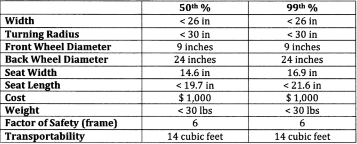
Constraints for the initial design of the LFC Prime are defined in Table 5. With this initial analysis and dimensional parameters defined, a three wheeled, rear
suspended, foldable design will be further researched.
50t% 99th%
Width < 26 in < 26 in
Turning Radius < 30 in < 30 in
Front Wheel Diameter 9 inches 9 inches
Back Wheel Diameter 24 inches 24 inches
Seat Width 14.6 in 16.9 in
Seat Length < 19.7 in < 21.6 in
Cost $ 1,000 $ 1,000
Weight < 30 lbs < 30 lbs
Factor of Safety (frame) 6 6
Transportability 14 cubic feet 14 cubic feet
Chapter 3
Frame Design
The first step is to compare different frame geometries with respect to theoretical weight, cost, suspension performance, transportability, and aesthetics. Once the geometry is selected, different materials can be compared that would optimize the design for weight, cost, and strength. Finite Element Analysis will finally be
conducted to ensure that the performance and safety of the design meets the functional requirements.
3.1 Frame Geometry
The initial LFC design, created for developing world countries by Amos Winter, was invaluable in designing the LFC Prime. It is important to note that Winter's frame was designed to be manufactured from steel, as it is most widely available across the developing world. This frame can be seen in Figures 9 and 10.
Figure 9: LFC frame designed for third world countries (Right View)
Figure 10: LFC frame designed for third world countries (ISO View)
Additionally Design Continuum, a design and engineering consultant firm in
Newton, Massachusetts, has created a frame design that will also be referenced. For this frame, its important to note it was designed for a single look-like prototype. This design was created to be aesthetically pleasing.
Figure 11: Design Continuum's LFC design (Right View)
Figure 12: Design Continuum's LFC design (ISO View)
From both of these designs, much information can be gleaned. The LFC Prime's design will utilize the tried and true aspects of the LFC and incorporate the aesthetically pleasing aspects of the LFC by Design Continuum.
3.1.1 Suspension
When designing a suspension system, it's important to analyze where typically the forces will act on the wheels if the LFC Prime were to be driven off road. From this, the necessary degree of freedom can be intuitively found.
Figure 13: Normal force on a rear wheel in an off-road environment
From Figure 13 it becomes apparent that having a trailing arm suspension, as typically done with motorcycles, would be optimal. It would be important to co-locate the axis of rotation of the suspension with the lever pivot axis. This is beneficial because otherwise a chain tensioner would be required.
There are two geometries that could be used for a trailing arm suspension for the LFC Prime. The two rear drive wheels could each be independently suspended, and in contrast they could be joined. To be specific, an independent suspension would allow each wheel to absorb shocks separately each having their own suspension components, while a joined suspension would fix the back wheels together having a single shock absorber. A quick comparison can be made of the two designs. The independent suspension design can be seen in Figure 14.
Figure 14: Independent suspension design
The joined suspension would be cheaper for the sole reason that the suspension parts are more expensive than the added frame geometry. Depending on if the suspension uses coil or gas shocks, the prices will vary from $20 to $500.
It can be hypothesized that due to the cantilever situation of the independent suspension design that the dimensions of the frame will have to increase for it to be equally as durable as the dependent suspension. Therefore, it can be hypothesized that the joined suspension design will be lighter due to the geometry and the one less shock needed.
The independent suspension will have greater performance if only one wheel were to collide with an obstacle and not the other wheel. This is because the wheel that collides with the obstacle will be able to deflect isolating the resulting motion to that single wheel.
The transportability is actually greater for the independent suspension design because the geometry allows for the front frame member to fold backwards easier. In the joined suspension design a jog in the geometry increased the range of motion for the front frame member though still isn't as foldable as the independent design.
Having the two rear wheels braced together will allow for a much more rigid design. The cantilevers of the independent design will be prone to yielding in collisions or during storage. This will decrease the fatigue strength and increase the potential for fracture or permanent bending.
Independent Suspension Dependant Suspension
Cost 0 1 Weight 0 1 Comfort 1 0 Transportability 1 0 Durability 0 1 Total 2 3
Table 6: Comparison between independent and dependent suspension design
The joined suspension would be the optimal choice for the LFC Prime, as it would theoretically cost less, have a smaller mass, and be more durable. Additionally, having a single shock would be more appropriate because a bicycle shock is designed for very similar loads as the LFC Prime. If two were used, the suspension may potentially be too stiff because each shock is experiencing half of the load.
3.2 Material Selection
Wheelchairs are made from a variety of materials. Some are manufactured from steel and aluminum while other higher performance wheelchairs are made of
titanium. Using the geometry found in the previous section, an optimal material will be found for the LFC Prime that will consider weight, strength, and most
importantly cost.
When comparing weight and strength the density (p) and yield stress (of) will respectively be used. To be specific, it is optimal to reduce the density and cost, while maximizing the yield stress. The rigidity can be considered though isn't
necessary to maximize as some flexibility in the frame can be beneficial. For the front frame member that attaches the front caster wheel to the pivot axis, it would make a softer ride for the user if the material weren't rigid because it would absorb shock from the front wheel.
The guidelines for when designing for minimum weight of beams and shafts (such as the frame members of the LFC Prime) is described by equation 8. (Ashby)
o2/3
MI = P (8)
To optimize the design for strength and weight, the material chosen should minimize the performance index M,. A graphical form can be seen in Figure 15. The optimal material will theoretically be in the upper left corner of the graph because this is where the density would be smallest and the strength would be the
largest. From this, it can be concluded that the possible materials that would be optimal are metals and alloys, glasses, composites, ceramics, porous ceramics, and some woods and polymers.
10,000 1,000 4-"
z
LU 100 10 Ceramics Composites1/Fams
Cerxnics: ra ,o orpresve smtergth eme mirnh tvpcali- 10% of coripewa.v
0the estetai strereth in fie reonkxreesio V 01
100 300 1,000 3,000 10,000 30,
+-Ught
DENSITY(kg/m')
Heavy
-Figure 15: Ashby chart of strength vs. density for general materials.
With further analysis of these groups of materials, the Young's Modulus can be compared with respect the density.
1,000 Ceramics Composites 100 Wood and wood product 0 Porous Metals
Ceramics and aNoys
Polmers ~01 Rubbers Foams 0.01 J J=I 100 300 1,000 3,000 10,000 30.000
+- Light DENSITY (kg/m 3) Heavy
-Figure 16: Ashby chart of Young's Modulus vs. density
For this case, it isn't necessarily optimal to maximize the Young's Modulus as some flex in the frame is desired. Ceramic materials are generally known for their ability to endure high temperatures and to be extremely stiff, though they are brittle. Furthermore, as soon to be shown the cost is very high. Therefore ceramic and porous ceramic materials will not be further analyzed.
With further research into each category, the possible materials are: oak, pine, polycarbonate, PET, CFRP, aluminum, steel, and titanium.
Finally the cost of the materials can be analyzed with respect to strength. Ideally it would be optimal to maximize the strength while minimizing the cost.
10,000 C U',1,000 Metals and alloys Po .-Porous Ceramics
Foams
cuOme me ts or n r-r ~~tr ~ ~ ~ ~ - 4Ur~~?<t Q00~W ~ewh ~ l(k r 0.01 +- Cheap 0.1V
COST (E/kg) rs 100 ExpensiveFigure 17: Ashby chart of strength vs. cost
100
10
From Figure 17, it can be concluded that metals and alloys would give the lowest cost per strength ratio. Composites, woods, and polymers could still be a possibility. To find a more accurate assessment of each material the performance index (MI) was calculated and shown in Table 7.
M1 Comments
Oak 28 - 36 Difficult to manufacture
Pine 35 - 40 Difficult to manufacture
Polycarbonate 14- 18 Injection molded
PET 9 -24 Injection molded
CFRP 43 -44 Expensive
Aluminum 20
Steel 5 - 18 Heavy
Titanium 20 Expensive
Table 7: Performance index of various materials
Note that the performance index for some materials is a range because the yield strength can change drastically depending on variations of the materials.
From this performance index, CFRP (carbon fiber composite) scored the highest for maximizing strength while minimizing the weight. Though inherently carbon fiber has a costly manufacturing process that would make it difficult to reach the LFC Prime's desired price target of $1000.
Wood materials oak and pine score just nearly behind CFRP. Again, to manufacture a wooden frame would be very difficult because wood isn't malleable or moldable. For precision parts it would have to be CNC milled or turned. This wouldn't be optimal because other methods such as injection molding or cutting, bending, and welding is a much cheaper.
The polymer PET scored next highest. There is no obvious reason why a polymer wouldn't work for this application. The manufacturing process will likely be
injection molding which at large quantities is an efficient method.
Aluminum and titanium scored closely under PET. Titanium is an expensive
material, which would again make the LFC Prime's desired cost hard to hit. Though, aluminum would be an appropriate material to use for this application. It can be purchased in standard size tubing that would fit the current geometry's design. The material is much lighter than steel though cheaper than titanium.
The design process will continue assuming that the frame of the LFC Prime will be manufactured from aluminum. Future research should be done that more
accurately rates the performance of polymers as an appropriate material for the LFC Prime.
3.3 Performance Verification
To verify that the frame will meet the functional requirements previously set, CosmosWorks FEA package within SolidWorks was primarily used. Due to this, a few modifications had to be made in order for a safety factor of 6 to be obtained.
Figure 18: Front frame member (red)
A problem during the analysis was on the front frame member. This member can be seen in Figure 18 (red). Due to the long cantilever beam, the stress near the
constrained portion of the member became high enough where the safety factor wasn't 6. This can be seen in Figure 19. The red represents the area that doesn't
have a factor safety of 6 while in contrast the blue represents the part of the member that does.
The green arrows represent the points where the part is constrained while the pink arrows represent where the force is applied. Additionally, having a factor of safety (FOS) of 6 means that the yield stress is at least 6 times greater than the stress measured.
Modef name Frort Frame Member Study n : Simuationxpress Study
Plot type: Factor of Safety Factor of Safety
Crterion : Max van ses Stress Red. FOS -6 oBlue
Figure 19: Red: represents the area under a FOS of 6, Blue: has at least a FOS of 6
The front frame member is constrained at two points. The first being at where the member rotates around the central axis to fold the LFC Prime. The second, located at the bend of the beam, is where the front frame member couples to the seat frame when the chair is in use. This is uncoupled when the chair is folded up.
To account for the stress concentration, material was added to change the cross section of the beam. With this new design, a second FEA analysis was done which can be seen in Figure 20.
Model name: Frord Frmae Member Study name: Simulaonxpress Study Pko type Fecdor of Safety Fador of Safety
Cririon: Max Yon Mises Stres
Red. FOS - 6 EBlue
III
Figure 20: Red: represents the area under a FOS of 6, Blue: has at least a FOS of 6, Note that there
isn't any red therefore the design has at least a factor of safety of 6.
The new design proved to meet the functional requirements previously set. A better visual of the stress concentrations can be seen in Figure 21. The red represents the
areas where the stress is highest while the blue represents the area of the member with the least or zero stress. Red doesn't necessarily mean it's bad as it simply shows the gradient of stress.
MOOinem Frort Fram Member
Study nm SmdoXpre Study Plt type Stdc nodl stress Stress
Deformoitan scowe 37.5851 vo Wkm (Nfn^2) 59,794,792 3 54,811,852.0 49,828,992.0 44,84605.0 39 863,19 34 88000 29,897,3980 24,914,498.0 19,3600 0 14,948,702 0 9,965,803.0 4,982,9050 8.5 --+Yleid s*renft 215000000.0
III1
Figure 21: Stress distribution of the front frame member.
A second area that was of concern was the rear frame member that constrained the wheels to the main pivot point, shown in Figure 22.
Figure 22: Rear frame member
This member rotates with the suspension. The analysis showed that all areas of the part had at least a factor of safety of 6. This is shown in Figure 23.
Model nae Ra Wheel Single Shock F- Member
Study name Snim arss Study
Pkat type. Factor of Safety Factor of Safety
Crterk. n - Wvo ssStres
Red - FOS - 6 -Ellu
Figure 23: Rear frame member has a FOS of at least 6
Modlm e Rea whee Singl Shock Fr-m Membe
Studyn Suligonprss Study
PlM "p Stalc ne str Defonnben .cat. 193 W5 von M5es (NMn^2) 21,465.4260 16,089,123.0 14,310,3550 12,521,587 0 10,732,8190 8,944,051 0 7,155,22 5 5,366,5145 3,577,746.5 1,788,978 6 210 6 -Yedsrnh:21500000 0
Figure 24: Stress distribution of the rear frame member
A similar analysis was conducted on the upper frame member, shown in Figure 25, which was also verified to have a FOS of 6.
The final point of interest was the axle for the pivot point of the suspension and the folding mechanism. This was estimated by the formula 11, where it's derived from equations 9 and 10. (9) 0 'shear =FIA A =;nr2 r 6F 7 r shear (10) (11)
Where the radius (r) is expressed with respect to the force exerted onto the shaft (F), the shear stress of aluminum
(
-,hear), and the factor of safety of 6. With thissimple calculation the minimum radius is determined to be 3 mm.
The final frame geometry for the LFC Prime can be seen in Figure 26, 27, and 28. All frame members meet the functional requirements.
Figure 26: Final frame for the LFC Prime (Right view)
Figure 27: Final folded frame for the LFC Prime (Right view)
Chapter 4
Conclusion
This new frame design adds much functionality to the existing Leverage Freedom Chair's design. The rear suspension will cushion the user during overcoming obstacles such as falls off a step and over rocks. The foldable frame allows for easy transportability for a wide range of automobiles. The higher ground clearance will aid in the off-road experience. And finally the simple aluminum frame design will help in lowering the cost of manufacturing.
As this paper only outlines a conceptualization of the frame, much further work will need to take place for the LFC Prime to be complete. Components will need to be mated to the design as well as the seat and levers. User ergonomics needs to be further studied to complete the folding mechanism as well as the logistics of a user getting into and out of the seat.
The optimization of the frame is merely the first stage of the LFC Prime. Though, the potential impact it could make on US users is huge, as it will drastically decrease their limitations in mobility. It is hoped that the success of the LFC Prime will some day aid in providing people with disabilities Leverage Freedom Chairs in developing world countries.
References
Ashby, MF. "Materials selection in mechanical design" Pergamon Press, Oxford, 1992
(February 2, 2002). Material Selection Charts. Materials. May 2, 2011, http://www-materials.eng.cam.ac.uk/mpsite/interactive-charts/default.html
Dreyfuss, Henry. The Measure of Man and Women. Wiley, 2001.
(September 2002). ADA Accessibility Guidelines for Buildings and Facilities (ADAAG). May 9, 2011,
http://www.access-board.gov/adaag/html/adaag.htm#toc
Winter V, A.G., et al. "The design and testing of a low-cost, globally-manufacturable, multi-speed mobility aid designed for use on varied terrain in developing and developed countries." ASME IDETC 2009. Paper# DETC2009-86808. (paper, presentation, student design competition poster)
Judge, Benjamin. "The Research and Design of a Low Cost, All Terrain, Mechanically Advantageous Wheelchair for Developed Markets" Massachusetts Institute of Technology. May 6, 2011