Design of a Folding Antenna-Integrated Micro UAV
byMy H. Vu
B.S. Mechanical Engineering
Massachusetts Institute of Technology, 2011
'MASSACHUSETTS INSFrE
OF TECHNOLOGY
NOV 12 2013
LIBRARIES
Submitted to the Department of Mechanical Engineeringin partial fulfillment of the requirements for the degree of Master of Science in Mechanical Engineering
at the
MASSACHUSETTS INSTITUTE OF TECHNOLOGY
September 2013
© 2013 Massachusetts Institute of Technology. All rights reserved.
Signature of Author:
Department of Mechanical Engineer
Avgsusfh ' 1'
Certified by:
David WallaceN Pr sor of Mechanical Engineering
A ,-~7hej§.upervisor
David E. Hardt Accepted by:
Design of a Folding Antenna-Integrated Micro UAV
byMy H. Vu
Submitted to the Department of Mechanical Engineering on August 9, 2013 in partial fulfillment of the requirements for the degree of Master of Science in
Mechanical Engineering
ABSTRACT
Micro-UAV devices can be used for a variety of purposes. This project is concerned with the design of such a device that will be used for high altitude antenna calibration. Such a UAV requires that an omni-directional antenna be integrated into the frame of the device to reduce signal interference. The device is to fold into a flare cartridge and withstand high deployment forces out of an aircraft. Design requirements include a rectangular working volume of 1.89" X 2.44" X 7.04", a minimum additional payload of 70 g, hang time requirements, and antenna operating frequencies. A standard design process was used to develop a functional prototype. Several different concepts were developed, analyzed, and tested until a discone parachute device was chosen. An umbrella-like mechanism that utilized aerodynamic forces for deployment was developed for the ground plane.
A functional demonstration prototype was built and tested to ensure the
device's survivability and deployment functionality. The results of the test were successful and proved that the design is viable and can be further developed and optimized to improve performance.
Thesis Supervisor: David Wallace
Acknowledgements
I would like to thank my advisor David Wallace for offering me guidance and
support throughout the research process. David provided valuable feedback and suggestions after every milestone of the process.
I would also like to thank Lincoln Labs and their members for their support and
advice through the project. Lincoln Labs presented the research problem and helped to define the scope of the project. They provided feedback on concepts and prototypes along the way as well.
Next, I would like to thank my colleague, Lauren Hernley, for her contributions to initial stages of the design process. Lauren was my research partner on the project for the first year and helped in the concept development and selection phases as well as the feasibility calculations for the parachute and balloon flight modes. She also offered advice and consultation in the later portions of the
project.
I would also like to thank John O'Sullivan and Daniel Huertas, two MIT
undergraduates, who assisted as UROPs for the project. They both assisted in providing background research and concept suggestions. John participated in the flight mode prototypes over the summer as well.
Finally, I would like to thank Troy Niekamp, another MIT graduate student, for his help with the testing stages of the final prototype. Troy volunteered a day out of his time to help set up and run the air cannon test and drop test. He also provided valuable advice and input.
Table of Contents
ABSTRACT 3 Acknowledgements 5 List of Figures 9 List of Tables 12 1 Introduction 131.1 Objective and Scope of Problem... 14
1.2 Related Research at MIT... 17
1.3 Antenna Background ... 18
1.3.1 Antennas Profiles of Interest ... 18
1.3.2 Radiation Pattern... 20
1.4 Principals of Flight... 21
1.5 Atmospheric Conditions ... 23
1.6 Deployment Conditions ... 24
2 Concept Development and Selection 25 2.1 Group Brainstorming... 25
2.2 Concept Down-Selection... 28
2.3 Final Selected Concepts... 31
3 Flight Concept Exploration 34 3.1 Feasibility A nalysis ... 34
3.1.1 Parachute ... 34
3 .1.2 B alloo n... . 36
3 .1.3 G lid er ... . 4 1 3.2 Prototyping & Testing ... 43
3.2.1 Parachute: Effects of Ground Plane Geometry ... 43
3.2.2 Glider: Addressing Stability Concerns ... 46
3.3 Feasibility Conclusions ... 48
4 Folding Concept Exploration 50 4.1 Pop-O ut D esign ... 50
4.2 U m brella Design... 52
5.1 Detailed Design ... 5 7
5.1.1 Final Folding Mechanism... 57
5.1.2 Modeling the Design ... 59
5.1.3 Antenna Integration ... 62
5.2 Device Fabrication ... 64
5.3 Deployment Package ... 68
5.3.1 Ejection Conditions ... 68
5.3.2 Design and Fabrication of the Deployment System... 69
5.3.3 Optimizing Space Usage ... 72
6 Testing the Device 75 6.1 Im pulse Survivability ... 75 6.2 Deployment Validation ... 78 7 Conclusion 81 7.1 Summary of Work... 81 7.2 Future W ork ... 84 7.2.1 Design Improvements ... 84
7.2.2 Progression to a Fully Functional Device ... 85
Bibliography 87
Appendix A: Parachute Feasibility MATLAB 89
Appendix B: Balloon Feasibility MATLAB 92
Appendix C: Glider Feasibility Calculations & MATLAB 96
Appendix D: Carbon Fiber FEA Report 100
Appendix E: Aluminum FEA Report 123
List of Figures
Figure 1: High altitude antenna calibration device [4]...14
Figure 2: MJU-10/B cartridge of outer dimension 2.0" x 2.5" x 8.0"... 15
Figure 3: Available system envelope [7]. ... 15
Figure 4: Schematic of flare cartridge system [7]. ... 16
Figure 5: Antenna integrated parachute UAV final prototype-close up (left) and opened state during drop test (right)...17
Figure 6: Dipoles and their radiation patterns (green): straight dipole, bowtie, and d iscone [4]. ... . 18
Figure 7: Three-dimensional discone monopole and it radiation pattern (green) [2] ... . . 19
Figure 8: Two-dimensional log periodic directional antenna and its radiation pattern (green) [4]... . 20
Figure 9: Omni-directional techniques for V-pol and H-pol [4]... 21
Figure 10: Folding concepts from top, left to right: (1) folding, (2) hinging, (3) twisting, (4) telescoping, (5) deformable, and (6) inflatable. ... 27
Figure 11: Flying concepts from top, left to right: (1) rotating airfoil, (2) parachutes, (3) stationary airfoil, and (4) lighter-than-air... 28
Figure 12: Ten fully integrated concept sketches... 30
Figure 13: Concept #1 - Discone parachute with folding ground plane... 31
Figure 14: Concept #2 - Balloon with printed or embedded antenna... 32
Figure 15: Concept #3 - Foldable dipole hang glider... 33
Figure 16: Position and velocity of chute. ... 36
Figure 17: Helium properties at sea level and 30,000 ft. ... 37 Figure 18: Volume at different altitudes for a balloon that would remain mutually
Figure 19: Figure 20: Figure 21: Figure 22: Figure 23: Figure 24: Figure Figure Figure Figure Figure Figure Figure Figure Figure Figure Figure 25: 26: 27: 28: 29: 30: 31: 32: 33: 34: 35: Figure 36: Figure 37:
Solution space for required payload and gas mass needed to remain a loft ... . . 4 0
Glider dimensions used in feasibility analysis. ... 41
Glider altitude v. Time with cutoff time of 30 min and cutoff altitude of 10,000 ft marked. ... 42
Ground plane prototypes from left to right going down: mesh circle, fabric circle, mesh square, fabric square, and "spider" ... 44
Left: Scaled-down parachute prototype with fabric square ground plane. Right: Weight added to prototype. ... 45
Hang glider prototype in three boom configurations: front, middle, back. Bottom images show corresponding Velcro connection points. ... 4 7 Unfolded sketch model and joints... 50
Folded sketch model. ... 51
Sketch model unfolding... 51
3D Printed connectors... 52
Left shows a labeled diagram of one spoke of umbrella folding mechanism; right shows an expanded view of the final spoke, highlighted in red. (Diagram not drawn to scale)... 53
Acrylic prototype open (left) and closed (right)... 54
CAD showing open and closed device... 58
FEA of carbon fiber spoke under initial loading conditions ... 60
FEA of Aluminum spoke under initial loading conditions. ... 61
Sectional view of UAV central strut with antenna integration... 63
Waterjet aluminum linkages (L2, L5, L3, L4) and 3D printed bottom and top center discs ... 64
Assembled folding mechanism with close up of pin joints... 64
Ground plane fabric with pocket for linkage. ... 65
Figure Figure Figure Figure Figure Figure Figure Figure
38: Ground plane with antenna hardware installed minus soldered cone
w ire s . ... . . 6 6
39: Closed and open device... 66
40: Top and bottom view of 3D-printed springer device... 67
41: Springs placed in the center of the folding mechanism. Left shows partially closed and right shows fully opened position... 67
42: Top plot shows the sabot's altitude and the bottom shows the velocity ratio both versus tim e... 69
43: Open sabot made of Al-5054 sheet metal... 70
44: Close-up of servo and opening mechanism with notches in tab and in opposite wall of second angle also shown... 71
45: Diagram of mechanism showing pin in locked position (left) and open position (right). Sidewall shown as green, bottom plate as blue, and pin highlighted in red. ... 71
46: Side view of UAV package with one face cut away. Components: sabot walls (green), payloads (magenta), parachute space (red), springer (yellow), UAV device (white and black in top left), and deployment electronics (bottom below payload). ... 72
47: 3D printed payload and springer mechanism... 73
48: Steps to properly packing the parachute inside the sabot... 74
49: Fully assembled deployment package. ... 74
50: Testing setup with air cannon and two cameras... 75
51: Test block and actual sabot with drag ribbon... 76
52: Trajectory of UAV (red) and sabot (blue) after being shot from air cannon at 35 PS I. ... 77
53: Trajectories of sabot (blue) and UAV (red) during drop test. ... 79
Figure Figure Figure Figure Figure Figure Figure Figure
List of Tables
Table 1: Design requirem ents... 17 Table 2: Atmospheric conditions up to 30,000 ft. ... 23
Table 3: Decision matrix of folding v. flight concepts for five antenna types. 29 Table 4: Testing matrix with varying ground plane configurations and
sum m ary of results. ... 46 Table 5: Comparison of performance between carbon fiber and Al-2024...62
1 Introduction
Unmanned aerial vehicles (UAVs) carrying antenna payloads can be used for various purposes. As it exists, the UAVs can create disturbances in the signal produced by the antenna. This research focuses on the development of a high altitude antenna calibration device where the antenna is integrated into the structure of the UAV. By doing so, extraneous structure is removed and a clean
signal can be sent back to the on ground device undergoing calibration.
The thesis is organized into the following chapters:
Chapter 1 presents the objective and scope of the research problem, describing design requirements and operating conditions of the device. Background on prior research, VHF antennas, and flight principles are also discussed.
Chapter 2 presents the methods used in concept development and selection of possible design solutions. Three promising solutions are chosen for further development.
Chapter 3 presents the results from the exploration of the flight methods employed by the three promising concepts. Feasibility calculations and quick sketch model prototyping narrow down the scope to one promising solution.
Chapter 4 presents the results from the exploration of the folding concepts. This includes the design and feasibility analysis of different folding mechanisms.
Chapter 5 presents detailed design and fabrication of the final mechanism and deployment system. This includes the CAD and physical prototypes for the
Chapter 7 is the conclusion of the thesis. A summary of the work is presented along with analysis of possible design improvements and future work.
1.1
Objective and Scope of Problem
The micro-UAV is intended to be an expendable device that will be deployed from a flare canister at a low altitude of around 30,000 ft and not recovered. Multiple devices are intended to be deployed from an airline carrier and used to establish a high altitude persistent OPS for antenna calibration.
psth"M OPShrw
-nsadber&*
Figure 1: High altitude antenna calibration device [4].
The UAV must fold down for storage in an MJU-1 0/B flare cartridge and on deployment, will unfold to its full structure.
Figure 2: MJU-10/B cartridge of outer dimension 2.0" x 2.5" x 8.0".
The cartridge sets the maximum system envelope for the UAV package at 48 mm x 62 mm x 180 mm with a 3.175 mm corner radius.
R 3.175 mm R 0.125 in 62rm 2.44 in 48 mm 1.89 in .I
Figure 3: Available system envelope [7].
Figure 4 shows the schematic of the flare cartridge system. The system envelope is encased by the shell of the flare canister and sealed with a cap, crimped at the edges to keep it locked to the shell. The ejection method from the flare canister is an explosive charge from the pyrotechnic cartridge that
pushes the UAV package with the piston. The force with required to open the cap is 125 lbf and the acceleration experienced during ejection is 300 G,
resulting in an exit speed of about 55 mph. J ,
180 MM 7.09 in
mchsm
8BU-36/8
Pyrotechnic
cartridge
Cap
180mm
Direction
of ejection
Figure 4: Schematic of flare cartridge system [7].
The flare will be deployed under the following conditions:
* Altitude: 5,000/30,00 ft AGL (min/max)
- Speed: 250 KIAS (max) * Duration: 1 to 3 hrs
e Weight: 4 lb (max)
* Temperature: -35 cold soak (max)
Only forms of unpowered flight will be considered in the design of the UAV to minimize the weight, size, and cost of the device. This also allows the payload it carries solely to be used to power the antenna structure rather than contributing to lift or thrust. The device's size and shape will be dictated by the geometry of the antenna necessary to operate in the desired frequencies. The following table summarizes the requirements that the UAV must satisfy.
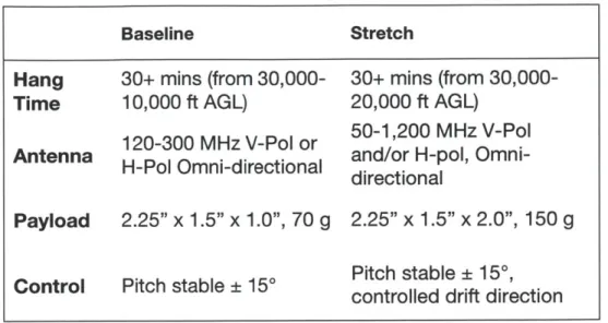
Table 1: Design requirements. Baseline Hang Time 30+ mins (from 30,000-10,000 ft AGL) Antenna 120-300 MHz V-Pol or H-Pol Omni-directional Payload 2.25" x 1.5" x 1.0", 70 g
Control Pitch stable ± 150
30+ mins (from
30,000-20,000 ft AGL)
50-1,200 MHz V-Pol
and/or H-pol, Omni-directional
2.25" x 1.5" x 2.0", 150 g
Pitch stable ± 15*,
controlled drift direction
The resulting design integrates a discone antenna into the structure of a parachute UAV. The cone of the antenna is formed by wires leading up to the parachute while the disc is formed by a umbrella-like mechanism that allows it to fold down into the flare cartridge.
Figure 5: Antenna integrated parachute UAV final prototype-close up (left) and opened state during drop test (right).
1.2
Related Research at MIT
A similar project was presented MIT's Fall 2010 Flight System Engineering class.
The goal of the project was to design a high-altitude persistence micro-UAV. The devices were similarly deployed from flare cartridges but used powered
acquisition at fixed altitudes. With the initial design established, MIT graduate student Tony Tao did further research into the design of the device in his
Master's thesis [7].
1.3
Antenna Background
The ultimate goal of this project is design a UAV that can have an antenna directly integrated into its structure. The type of antenna as well as desired operating frequency will dictate the geometry and size of the required device.
1.3.1 Antennas Profiles of Interest
Five antenna profiles were chosen for the project: dipole, bowtie, discone, bicone, and log periodic. They are listed in order from simple to complex. Greater bandwidth is achievable with a more complex design. These antenna profiles were chosen as a base due to their simplicity and omni-directional capabilities. Their geometries could also be easily adapted into a UAV.
Figure 6: Dipoles and their radiation patterns (green): straight dipole, bowtie, and discone [4].
The straight dipole antenna is the simplest antenna that could be adopted. It can be created using a wire or a strip. Increasing its width effectively increases its bandwidth as well. The bowtie antenna is essentially a dipole antenna that has been fanned out for better performance. Both of these are two-dimensional dipole antennas. One of the most commonly used antennas is the
half-wavelength dipole, which will be considered in this study [1]. By rotating a bowtie antenna about its z-axis, a three-dimensional bicone antenna profile can be achieved for broadband capabilities. The operating wavelength for these antennas is governed by Equation 1:
Adipole - Eq. 1
2v
Figure 7: Three-dimensional discone monopole and it radiation pattern (green) [2].
Another antenna design of interest is the discone, which is formed by placing a monopole cone above a conductive ground plane. This causes energy from the actual source to radiate in all directions. Waves radiating from the source will undergo a reflection below the ground plane (Balanis, 1982). Ideally, the plane is infinitely large so that a quarter-wavelength monopole antenna would be
equivalent to its half-wavelength dipole counterpart. Although this is not the case, the use of a large enough ground plane will result in a radiation pattern that sufficiently simulates this. Typically, the length of the cone sides, ldiscone, is
an angle between 25 and 40 degrees. The disc is 0.7 times one-quarter of the minimum frequency's operating wavelength.
C Xcone =
Adisc = 0.7" - cone
Eq. 2
Eq. 3
In the case of the bowtie, discone, and bicone configurations, the antennas do not need to be formed with continuous surfaces. Rather, materials such as a mesh surface or many wire tines can be used to create the outline of the shape.
Figure 8: Two-dimensional log periodic directional antenna and its
radiation pattern (green) [4].
Finally, log periodic antenna was also considered. It is a type of antenna configuration that closely parallels the concept of frequency independence, meaning the antenna can accommodate the entire frequency band of a given system.
1.3.2 Radiation Pattern
One parameter of interest is the radiation pattern of the antenna. The desired antenna would produce an omnidirectional radiation pattern. This type of pattern
is essentially non-directional in a given plane and directional any orthogonal plane. A directional pattern is one in which the radiating or receiving
electromagnetic waves are more effective in some directions than others (Balanis, 1982). The antennas can then be placed in different configurations to accomplish omni-directionality in either V-pol or H-pol. The possible
configurations are shown in Figure 9.
V-Pol H-Pol
Single Monopole/Dipole
Directional Array
Orthogonal Dipole Pair
Directional Array
Figure 9: Omni-directional techniques for V-pol and H-pol [4].
1.4
Principals of Flight
This study is concerned primarily with unpowered flight. The typical
FL = A 1Pair(h) v2CL Eq. 4
1
E
FD= APair(h)V2CD Eq.5 2ar
These forces are dependent on the dynamic pressure, pairv 2, which is a 2
function of altitude, the force coefficients, and the area of the device (wing planform for wings and frontal area for bodies).
Exploring the design space, there are several different options that can be pursued. One option to be considered is stationary airfoil vehicles such as fixed wing gilder planes, hang gliders, kites, and other similar devices. These are characterized by their lift to drag (LID) ratio to evaluate performance.
Rotary airfoils considered in this study include devices that utilize a propeller for its main form of lift. Since only unpowered flight is being explored, auto-gyros are of particular interest. These devices have rotor blades that spin through the upward movement of air. They are positioned at such an angle so that flow of air produces a lift.
Lighter than air devices are also considered. Particularly, we are interested in larger sized weather balloons. The fidelity of such a device will depend on its ability to remain buoyant at the desired altitudes. Buoyancy is equivalent to the weight of the volume of liquid-in this case air-that has been displaced and is also changing as a function of height.
Fb = Pair (h)'Vair Eq. 6
The lighter than air system will remain neutrally buoyant or aloft if the following condition is satisfied.
Fb - mtotg _> 0
Eq.
7
Parachute devices will also be considered. These are drag devices and the amount of drag they are capable of producing is dependent drag coefficient of the chute's geometry.
1.5
Atmospheric Conditions
During the 20,000 ft descent, the device will be undergoing changing atmospheric conditions that will affect the performance of the device. The
following table summarizes the changing atmospheric conditions at the altitudes of interest.
Table 2: Atmospheric conditions up to 30,000 ft [8].
Altitude Temperature Acceleration Absolute of Gravity Pressure Density Air ViscosityDynamic
(ft) (C) (kg*m/s) (N/mi (kg/mi) (N*s/m) 0 15.00 9.806 101325 1.225 488003.737 5000 5.09 9.802 84309 1.055 488003.637 10,000 -4.80 9.797 69692 0.905 488003.534 15,000 -14.69 9.793 57206 0.771 488003.43 20,000 -24.59 9.788 46602 0.653 488003.324 25,000 -34.47 9.783 37652 0.549 488003.217 30,000 -44.35 9.779 30151 0.459 488003.107
At higher altitudes, the drag forces on the device are much lower due to a significant reduction in air density. The temperature, however, is also much
1.6
Deployment Conditions
Upon deployment, the UAV will be shot out of flare canisters at an explosive acceleration of 300 G. Assuming the impulse lasts for 0.1 seconds, the device will accelerate to a relative speed of about 29.4 m/s (65.8 mph). Combined with the speed of the jet at 250 KIAS, this equates to a total speed of 128.6 m/s
(287.7 m/s) before slowing down to terminal velocity. Additionally, 125 lbf is
required to break through the lid of the flare canister [7].
To help survive these deployment conditions, a sabot was also be designed to encapsulate the antenna UAV. The sabot will be responsible for taking much of the initial impulsive forces and to decelerate the package to a reasonable terminal velocity before ejecting the antenna.
2 Concept Development and
Selection
In order to develop a suitable solution for the project, several rounds of
brainstorming and concept generation were employed. The problem space was broken down into three categories: antenna type, flight concept, and folding mechanism. Possible solutions were independently developed for the each of the latter two areas of concern, while taking into account the geometry and functionality of the five antenna types.
Once a substantial number of ideas were generated, they were organized into similar categories and the promising ideas for the two categories were
integrated into ten full solutions. The top three promising solutions were selected for further prototyping.
2.1
Group Brainstorming
To quickly generate many ideas, group brainstorming sessions were held with experts in the areas of fluids, flight, and mechanical design. Participants were divided into sections focusing on idea generation for flight methods or folding mechanism, depending which subject better suited their area of expertise.
For each session, participants were shown five shapes related to the five antenna types and given the challenge to come up with as many ideas as
possible for one of two prompts:
(1) How would you make this shape stay fly/stay aloft for an extended
period of time, unpowered?
The participants were not informed that the end goal was to incorporate this into an antenna integrated UAV so as to not introduce bias and limit their range of ideas.
Each shape was introduced to them one at a time and they had three minutes to independently develop and roughly sketch out their ideas. At the end of fifteen minutes, everyone briefly presented his or her ideas. The ideas were categorized
by shape and briefly discussed.
The next phase of the exercise broke the group up into small teams of 2 to 3 people. Each team was asked to pick one or two designs and spend 10 minutes refining their ideas. Once again, each team discussed the refined ideas to all members of the session.
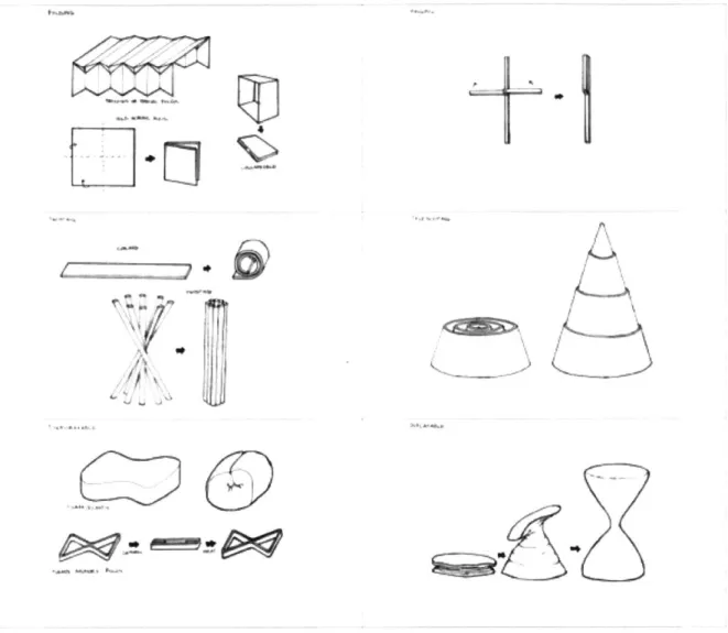
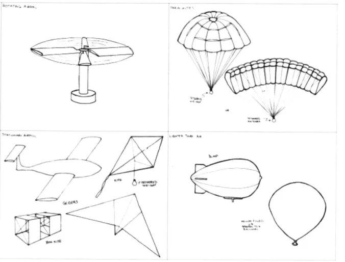
From these sessions, common themes emerged for each antenna type. There were several duplicates and variations for certain concepts. To better analyze the large amount of results, common ideas were grouped into categories to define the problem space. Figures 10 and 11 summarize the concept categories for flight methods and folding concepts.
4~2~
m4
9'
0
Figure 10: Folding concepts from top, left to right: (1) folding, (2)
hinging, (3) twisting, (4) telescoping, (5) deformable, and (6) inflatable.
k1--C
2
a'-Li ~ S. ~~jrn~
"6 .Figure 11: Flying concepts from top, left to right: (1) rotating airfoil, (2)
parachutes, (3) stationary airfoil, and (4) lighter-than-air.
2.2
Concept Down-Selection
Once the concepts were categorized, a decision matrix was used to evaluate the ideas. Table 2 shows the matrix with folding categories on the horizontal and flying antenna concepts on the vertical. The antenna concepts on the vertical are further grouped into the flying concepts presented in the previous section. The x's mark all the different combinations of ideas that were generated. The top most interesting concepts are highlighted in yellow.
Table 3: Decision matrix of folding v. flight concepts for five antenna types.
Folding Hinging Twisting Telescoping Deformable Inflatable
Dipole Glider x x x x x x
Log Periodic Glider x x x X X
Glider with Bowtie in
Wing x x x x x
Log Periodic or
Dipole Kite
Dipole Pyramid Kite x x x x
Bicone Box Kite x x x x
Bow-tie Box Kite x x x
Vertical Log Periodic
Turbine
Dipole or Bowtie
Rotor
Dipole Maple Seed
Helicopter
Discone with Ground
Plane Rotor X X X X X X
Bicone with Rotors x
Discone with Ground
Plane and Metal x x x
Twine Cone Any Antenna Tethered to Chute 2D Antenna Integrated in Chute Antenna Tethered Balloon X X X X X Antenna-Shaped Balloon Balloon Inside Discone or Bicone X X X
The ten promising ideas were further developed and concept sketches of these solutions were created. The sketches presented full high-level solutions for how all three areas-flight, folding, and antenna geometry-could all be integrated. The concept sketches are shown below:
D ascom Ptu* DOn" PW&Outk Mao A*OxwNer Dft Tvac~ong Dwsn Avowel T OpWW
r 7)
Figure 12: Ten fully integrated concept sketches.
The three autocopter concepts (Fig. 7, row 1, #3-5) would have been too complex in design to pursue and determined to have poor endurance
performance. The collapsible balloon was determined to be an unnecessary over-complication while the kite was determined to be a less stable
configuration of the glider concepts. The most promising concepts were a discone parachute device (Row 1, #1), a balloon (Row 2, #2), and a
2.3
Final Selected Concepts
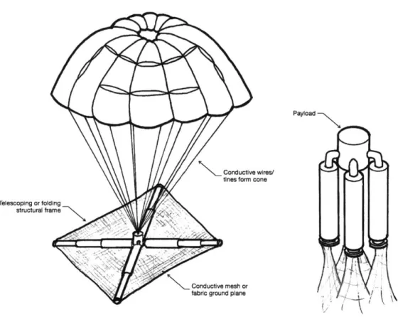
Conductive wires/ tines form cone
Telescoping or folding structural frame
Conductive mesh or fabric ground plane
Payload
Folds up Into system envelope.
Figure 13: Concept #1 - Discone parachute with folding ground plane.
The parachute design chosen would form a discone antenna. The tines of the chute would form the cone of the antenna by running current through them. A conductive mesh or fabric such as aluminize Mylar would be used to form the ground plane. To maintain the structure of the plane, a collapsible lightweight frame that could fit into the system envelope would be used. Challenges
associated with this design include endurance time, stability challenges, ground plane deployment/unfolding mechanism, structural strength of ground plane, and the effects of the ground plane on parachute performance.
Wire dipole antenna embedded (or printed on surface)
Payload
Figure 14: Concept #2 - Balloon with printed or embedded antenna.
The balloon concept was chosen for its simplicity. It would simply be a large balloon that would be inflated after deployment from the flare canister via a lighter-than-air (LTA) compressed gas canister. The antenna would simply be printed on the surface of the balloon or embedded inside with metallic tines. The payload would be tethered to the bottom of the balloon to provide some stability as it descended. Challenges associated with this design direction included survivability and the effects of system envelope volume restriction on the amount of gas available to fill the balloon.
FoW upU uWVJf
Figure 15: Concept #3 - Foldable dipole hang glider.
The final design considered is that of a collapsible hang glider. The frame of the hang glider would be constructed from a sturdy and lightweight material that could fold up into the system envelope. The frame would need to fold up using elastic or spring-loaded joints. The main struts of the hang glider would form the two dipoles of the antenna. A light but strong fabric such as rip-stop nylon would be used to create the wings. The payload would then hang below the glider to provide balance and stability. Challenges associated with this design included endurance time, durability and strength of frame, flight stability without active control, and ability to fold into desired system envelope.
3 Flight Concept Exploration
In order to choose one concept to pursue, the three potential designs were evaluated for feasibility. This was done through size and flight calculations, research into the different flight methods, and quick sketch model prototyping and testing.
3.1
Feasibility Analysis
The baseline design requirements for the project are used to determine the feasibility of each design. The device must have an endurance of thirty minutes from a descent of 30,000 ft to 10,000 ft with a payload of 70 g. The lower end of the antenna operating frequency dictates the minimum size of the fully opened device. The baseline requirements specify a minimum operating frequency of
120 MHz which can be used to determine required antenna dimensions.
3.1.1 Parachute
The parachute design calls for a discone antenna. To satisfy operating
conditions of at least 120 MHz, Eq. 2 and 3 can be used to determine the proper dimensions. Such a parachute calls for a ground plane with a diameter of 0.437
m and a cone side length of 0.625 m. The suggested cone angle is between 25 and 40 degrees, which correspond to a chute diameter between 0.528-0.803 m.
For this analysis, a circular chute (Fruity Chutes Elliptical 30" (0.762 m) parachute with a drag coefficient of 1.55 is used.
The total mass assumes the required payload of 70 g (mq), the mass of the parachute (mp), and the mass of the ground plane (mg).
mtot = mreq + mP + mg Eq. 8
Nylon density of 0.061 kg/M 2 is used to calculate the mass of the parachute. A half sphere is used to approximate the surface area of the chute. The mass of the chute is estimated to be 0.056 kg.
mP= 2Pnylonfr 2 Eq. 9
The structural frame of the ground plane is assumed to be eight spokes of
carbon fiber about .25" square cross section. The density of carbon fiber is 1600
kg/M3. The rest consists of a nylon conductive fabric plane. The ground plane is
estimated to be 0.113 kg.
mg = 8pCF(0.25 2r) + pnyionTr 2 Eq. 10
To determine the parachute's position and endurance time, the following equation is integrated assuming an initial vertical velocity of 0 and a starting altitude of 30,000 ft.
dv A pair h)V2CD Eq. 11
Parachute Altitude v. Time - 30-inch Chute 25-- Limits 20 -15 0 10 X: 1882 5 - Y: 10 0 -0 200 400 600 800 1000 1200 1400 1600 1800 2000 Time [s]
Parachute Velocity v. Time
0 12 3 -40 200 400 600 800 1000 1200 1400 1600 1800 2000 Time [s]
Figure 16: Position and velocity of chute.
For the given assumptions, a parachute device would exceed the required
minimum hang time of 30 minutes. In regards to the size constraints, the
packing volume of such a chute is orders of magnitude below the given maximum volume of 0.021 M3
. The ability to fit within the sabot is solely
dependent on what kind of folding mechanism can be developed.
Based on this primary analysis, a parachute device would be viable. Different parameters could also be varied to even further increase the endurance time. An additional concern that would need to be tested in future steps is the effect of the ground plane on the performance of the chute. Would the ground plane interfere with proper chute deployment and does the geometry of the plane matter?
3.1.2 Balloon
The design calls a dipole antenna stretch across the diameter of the balloon. According to Equation 1, the minimum antenna length, and therefore
corresponding the balloon diameter, must be 1.25 m. This requires a balloon volume of 1.634 M3 . The analysis assumes that balloon will stay neutrally
buoyant the deployment altitude of around 30,000 ft. Helium would be used to fill the balloon. The following plot shows the density of helium with varying
altitude.
3
Helium Density v. Altitude I' 28 I-26 24 --0 0 0 22- 20--18 F 16 - 14---12 1A 0.06 0.07 0.08 0.09 Density 0.1 [kg/m3 0.11 0.12 0.13
Figure 17: Helium properties at sea level and 30,000 ft.
To remain mutually buoyant, Equation 7 must be satisfied. Due to the changing density, the balloon volume will also be affected depending on where the balloon is. The balloon is smallest at its lowest point of 10,000 ft where the density of He is about .125 kg/M3 . To achieve this volume, 0.204 g of He is
needed. The following plot shows the balloon's volume at various altitudes:
.~~~ ~ ~ - . .
. ~ . - ....
.~~~ ~ ~ ~ -. .
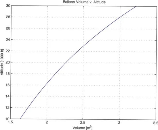
.-Balloon Volume v. Altitude 30 28-- 26---24 -. 22-20 -18 - . 16 F. 14 F 12 F 10' 1. 5 2 2.5 Volume [M3 ]
Figure 18: Volume at different altitudes for
mutually buoyant at 10,000 ft. a balloon that would remain
At 30,000 ft, the balloon has an initial release volume of 3.221 M3 . There are
several types of weather balloons available: pilot, ceiling, and sounding
balloons. Sounding balloons are larger and used at higher altitudes, appropriate for this application. The first concern is whether or not an appropriate balloon exists which will not burst. To determine this, the burst data for sounding balloons can be used. The Hoskin Scientific Company [3] has several balloons that can be used-any of their balloons model TA 350 or higher would perform adequately.
Next, we can determine the payload range necessary to achieve successfully flight. The baseline requirements specify a payload mass 70 g (mr,).
Additionally, we must account for the mass of the metal tines (m) that will be used for the antenna and the weight of balloon's latex (mi).
F 0 0 U) 3 3.5 - - . ... ..- ... - ... ... ... ...-.. -- ... -... . ... ...
Mballoon - Mreq + MW + M,
To determine the length of wire needed for the antenna, four circumference lengths of the balloon cross-section are used. Using 18 gauge copper wire with a density of 0.00728 kg/M3, the mass of copper is determined to be 0.114 kg.
M= 4Pc rcr 2 Eq. 13
A conservative range for the balloon latex mass should be at least 0.35 kg and
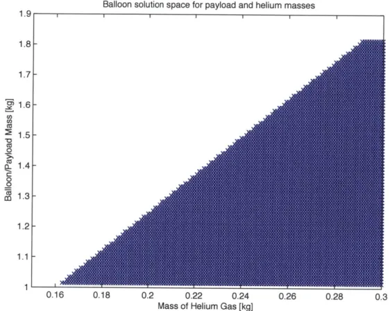
no more than 3 kg. According to the Hoskin burst data, an upper limit of 1.0 kg was sufficient for our analysis, having a burst diameter much larger than what we needed. This corresponds to a balloon mass range of 1.164-1.814 kg. To determine the solution space, Equations 6, 7, 9, and 10 are combined to yield:
(
Pair1~mEq.
14
(Pr MHe ~ Mballoon 0
Pue
Balloon solution space for payload and helium masses 1.9 1.8 1.7 1.6 CO) 1.5 Ca 0 oz 1.4-C 0 0 M' 1.3 1.2 1.1 1 0.16 0.18 0.2 0.22 0.24 0.26 0.28 0.3 Mass of Helium Gas [kg]
Figure 19: Solution space for required payload and gas mass needed to
remain aloft.
Using helium's vapor density of 0.138 kg/m, only 0.0029 kg of helium can be stored within the sabot. According to Equation 11, the maximum supportable payload for successful flight must be less than 0.0186 kg. This is much lower than the required payload. Additionally, balloons are difficult to control and neutral buoyancy is near impossible without active control. In this analysis, it is assumed that the balloon stays neutrally buoyant at deployment, but in reality, any change it experiences will cause it to undergo volume changes. With these factors in mind, the balloon design was eliminated and a physical prototype was not pursued.
3.1.3 Glider
A hang glider was also of particular interest. The boom of the glider would serve
as a dipole antenna and help to maintain stability. As mentioned in the previous section, the boom would need to be 1.25 m. Suspending such a boom from the glider lowers the center of gravity and increases its rotational stiffness, similar to a pilot and control frame [2].
The analysis assumes a glider based upon the Prism 4-D Ultra-light Stunt Kite of the following dimensions:
30*
I1.168
m
h =0.584
b =
1.626m
Figure 20: Glider dimensions used in feasibility analysis.
The frame of the glider can be approximated to be a triangle with rods of a circular cross section of 0.125". The total mass is estimated to be 0.902 kg.
mtot = mreq + PCF(2 1 + b)(wO.1252) + 0.5 pnY
1onbh Eq. 15
Maximum endurance of a glider occurs at minimum power. The lift coefficient at minimum power is given by the following equation, where CDO is assumed to be somewhere between 0.012-0.015 [5] and K is dependent on the glider geometry (refer to Appendix C for full derivation) [6]:
Eq. 16
CL 3CO
J K
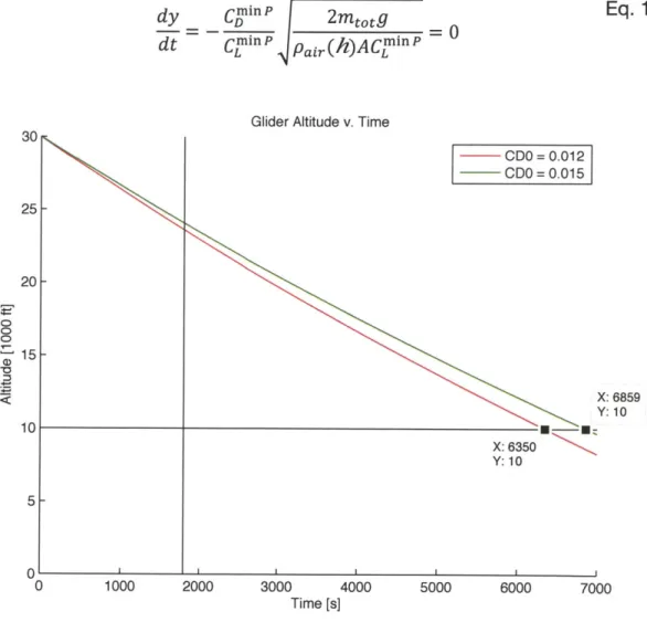
CD = CDO +KCL + COOm Eq. 17 To determine the position of the glider, the following equation was integrated [6]:
Eq. 18
dy CDLinP _tOt_
dt Cj"'' Pair(h)ACL
Glider Altitude v. Time
0 1000 CDO = 0.012 CDO = 0.015 X: 6859 Y: 10 . . X: 6350 Y: 10 2000 3000 4000 Time [s] 5000 6000 7000
Figure 21: Glider altitude v. Time with cutoff time of 30 min and cutoff altitude of 10,000 ft marked.
A glider would exceed the required time conditions and even meet stretch
requirements. Additionally, hang gliders posses many other desirable qualities. Its dynamic stability properties are very similar to that of a conventional airplane
30 25 F 20 P 15 10 5 0
except the lateral directional stability margins are significantly larger [2].
However, gliders also have a spiral stability mode that would be detrimental to the performance of the device [2].
For successful flight, frame must be structurally sound to achieve necessary lift and avoid stability issues. A viable glider would require a complex framework that would be difficult to fold or collapse down into the volume constraints of the system envelope. The weight of a complex structure would also decrease the estimated endurance time, making the glider a less attractive design option.
3.2
Prototyping & Testing
After additional research on the different flight methods and performing initial feasibility calculations, general conclusions could be drawn but there still remained a few areas of doubt. To gain more clarity on the two remaining
concepts of interest, simple sketch models were created to test critical areas of concern.
3.2.1 Parachute: Effects of Ground Plane Geometry
One area of concern that still existed after performing the feasibility calculations was the effect of the ground plane on the parachute's deployment and
performance. Quick prototypes were constructed for five ground plane variations and a simple drop test was performed.
The ground plane of the prototypes were created using balsa wood, spring steel, polyester mesh, and/or conductive fabric. The five designs were: mesh square, fabric square, mesh circle, and fabric circle, and wire tines (or "spider").
In particular, we wanted to see the effect of geometry on the performance. Additionally, it was also desirable to see if the existence of a large plane would
impede the flow of air needed to fill the chute. Mesh and fabric ground planes were used to test this as one let more air through than the other. The "spider"
design was even more minimalistic, eliminating the plane area completely and creating the plane with a circular array of metal tines.
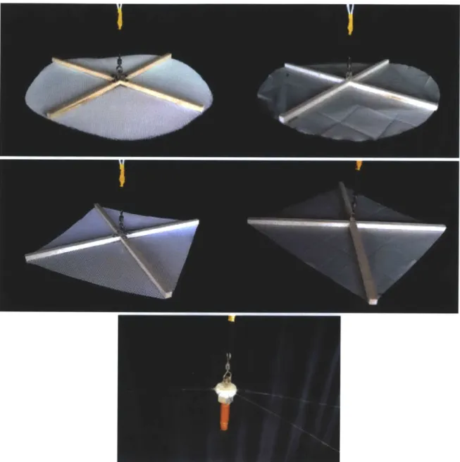
Figure 22: Ground plane prototypes from left to right going down: mesh
circle, fabric circle, mesh square, fabric square, and "spider"
Each device was then attached to the center of the planes to bring the total mass to 115±1 g. Laser cut acrylic hooks were used to tether the planes to the parachute. The parachutes were 18"-diameter circular chutes.
Figure 23: Left: Scaled-down parachute prototype with fabric square
ground plane. Right: Weight added to prototype.
The devices were then dropped off from a three story building of about 30 feet and a video camera was used to capture the descent from two angles-one shot perpendicular to the descent and another from the ground. The fall rates and general performance of each device was noted. The next table presents a matrix the varied design parameters and their respective performances during the test.
Table 4: Testing matrix with varying ground plane
of results. configurations and summary
Mesh Fabric Mesh Fabric Wire
Circle Circle Square Square Spider
Area 254.47 in 2 254.47 in 2 162 in 2 162 in2 Ngiil
Area (D = 18 in) (D = 18 in) (13"1 x 13") (13"1 x 13") N giil
Time 4.8 s (Crashed)
Rigid mesh
Rii ehfabric
Drag from Mesh veryMsvey
fabric
Drag fromMin.
LightweightPros preserved increased durable increased material
shape fall time fall time Survived
crash
Little Little Slack from No
additional Took a lot of additional fabric did additional
Cons drag damage drag not retain
drag
contribution contribution shape contribution
Testing suggests the addition of a ground plane adds to the drag of the device through the air, improving flight endurance performance. This suggests that the plane should be created with solid fabric rather than just a wire framework or perforated material.
Though it is difficult to make a conclusive statement about the geometry of the plane, the shape does not seem to have a significant effect. Different factors were considered to determine which geometry to pursue. Though the square plane maintained its shape better, a typical discone antenna employs a circular ground plane. Additionally, the radial symmetry would facilitate the design of a foldable mechanism that could expand to 18" (diameter or diagonal length) but foldable to something that could fit in the small volume of the flare canister.
3.2.2 Glider: Addressing Stability Concerns
The glider concept could theoretically achieve reasonable flight endurance. However, a few concerns still remained:
(1) What kind of effect would the required 1 m boom would have on the
performance of the device?
(2) Where should the boom be positioned to maintain the best stability and would active control be required?
To create the sketch model, an existing stunt kite (Prism 4-D Ultralight Stunt Kite) was modified to include the additional antenna structure. A one-meter rod of balsa wood was wrapped in aluminized Mylar and affixed to the kite using Velcro so that the boom could be moved relative to the center of mass. A payload of 70 g was put at the end of boom where the center of mass was determined to be located. The lowered position of the boom would theoretically increase the control sensitivity [2]. Three strings were used to help stabilize the position of the boom.
Figure 24: Hang glider prototype in three boom configurations: front,
The glider model was then ready for testing. The intended procedure was to bring the glider to a four-story drop zone, adjust the position of the boom, and evaluate the performances of each configuration. However, when testing commenced, it was very difficult to get the glider to achieve stable flight.
Regardless of the position of the boom, the prototype wanted to flip. This made testing with the model impossible and reconfirmed existing doubts about its feasibility.
After further evaluation, it was concluded that even if stable flight could be maintained without active control, the glider possessed too many parts to maintain structure that it would be very difficult to develop a mechanism that fold and auto deploy the glider but also fit within the limited size constraints.
3.3
Feasibility Conclusions
After narrowing down the initial ten concepts to three, a first-order feasibility analysis and sketch models were used to pick the most promising concept to pursue a detailed design for. Feasibility calculations showed that a lighter than air UAV device could not satisfy the design constraints. Changing altitude and atmospheric conditions had too significant of an effect on balloon performance making it difficult to design a reliable device. Additionally, the size constraint could not be met with a balloon since the volume of compressed gas needed exceeded available canister space.
Calculations suggested that both a parachute and hang glider design could potentially work. However, pursuing a glider would be quite complicated. Stability issues remained a significant concern due to its bistable nature. The lack of symmetry and abundance of structural parts would also make the design of folding mechanism that could fit in the volume constraints very complicated and close to impossible--such a device frame would have to be inflatable. Pursuing such a design would pose too many risks.
The parachute concept had the most potential given the time frame and scope of the project. Calculations suggested that required parameters could be met and testing help to address potential concerns were not a big issue. It was a simple and elegant solution that could be easily implemented and thoroughly explored. The fewer areas of concern and parameters to worry about made it so that optimization of the design could be easily achieved.
4 Folding Concept Exploration
The next step in the design process was to prototype different mechanisms to fold up the ground plane. To achieve a baseline operating frequency of 120 MHz, the plane would have to be at least 17.2" in diameter while fitting in a
1.89" x 2.44" x 7.09" space. The mechanism would also have to be robust
enough to withstand impulsive forces-once during the initial cartridge ejection and again when the parachute opens-as well as retain its structure during the descent. It would also have to be lightweight enough to help reduce weight and thus increase endurance time. Two designs were developed and quickly
tested-a pop-out tent inspired one and an umbrella inspired one.
4.1
Pop-Out Design
The first design uses spring-loaded hinges to unfold two sets of armatures out from a central spine.
The framework is composed of circular carbon fiber tubes that fold up against one another to be stored inside the cartridge. Torsional springs were glued in between 6-inch tubes of carbon fiber to test the folding and sizing of the structure.
The structure would automatically open as desired, but it would droop due to the weight of the tubes. In order to constrain each armature from sagging down below horizontal, joints were designed for each specific location. Each pair of joints would create hard stops to prevent over-rotation. Three types of
connectors were designed to form the necessary joints: three way connector, four way connector, and single connector.
Figure 28: 3D Printed connectors.
The joints, although preventing over-rotation, did not lock the mechanism into place. This meant that the arms could deflect away from their desired positions given a gust of wind. Additionally, the connectors were bulky to accommodate for the different degrees of freedom each one needed to support. The design, however, did accomplish its goal of folding a large ground plane down into the available working volume supplied by the cartridge. If optimized, it could even be used to fold down a 41.2" diameter ground plane needed for the stretch requirements of a minimum operating frequency of 50 MHz.
4.2
Umbrella Design
The second design takes its inspiration from an umbrella. The mechanism consists of eight spokes around about a central strut. The spokes utilize a four bar mechanism with two of its members pinned to two central strut and left free to rotate. One member is constrained from moving along the central strut while the other is allowed to slide up and down. This sliding motion opens and closes the mechanism.
S.
Figure 29: Left shows a labeled diagram of one spoke of umbrella folding mechanism; right shows an expanded view of the final spoke, highlighted in red. (Diagram not drawn to scale)
Figure 29 shows a diagram of what one spoke would look like and labels different parameters that can be optimized. Each member and its length is labeled with L#. Input parameters were chosen to be:
(1) Distance between L2 and L3 when opened (H)
(2) Span of the mechanism when opened (S, + S2)
(3) Length of the mechanism when closed (Lj)
(4) Angle between L, and L2 (0,)
(5) Angle between L5 and L2 (0,)
The additional parameters were calculated using the following equations:
L S1 Eq. sin 01 x = L1 - L2 Eq. .19 20 H I P
92 = 2*tan' (cos0 1 -H + L *sin 0) H L4 = L2 - ( sin 0 + X CO 1+tan 02) sin 01 La in6(Lsin 02 2 -L 4) L. = 2 * tan-1 ( S2 ) + \COS(90 - 01)) Eq. 21 Eq. 22 Eq. 23 Eq. 24
A sketch model was then created once a set of workable dimensions was
established. All the pieces were laser cut out of 1/8" acrylic, with each strut measuring 1/4" wide. The members were held together with half pressed rivets to serve as pin joints.
Figure 30: Acrylic prototype open (left) and closed (right).
The sketch model served as a proof of concept in the mechanism's ability to fold down an appropriate size. The structure met the minimum 17.could also not be expanded much past 18". This is because any additional four bar linkages to
extend the length would increase the size of the closed mechanisms, exceeding the space constraints given. The design revealed interference points between
linkages and pin joints. These could be addressed, however, by adding spacers between the linkages so that they could fold past one another. The prototype also showed a potential area of bi-stability that could potential pose an issue to the structure's integrity.
The model showed that this design provided a more rigid structure for the
ground plane and thus had better potential to withstand high deployment forces. Additionally, the friction in the design suggested that it could maintain an open state without the need of a locking device. To open such a mechanism, the one of the central discs that the linkages were attached to could be tethered to strings of the parachute. The aerodynamic forces generated from the parachute deployment could then pull the slider up and open the mechanism.
4.3
Choosing a Mechanism
The two mechanisms both were able to successfully fold a large ground plane down to the available volume. Both designs were then evaluated for
compactness when folded, simplicity and part count, structural integrity, and ability to resolve existing concerns.
Although the first design could potentially fold up a larger ground plane with little difficulty, the mechanism's structural integrity was at question. It could not
maintain its shape very well and drooped under its own weight. A locking device or stiff elastic joints could potentially solve the problem. However, having
locking capability added complexity and parts to the design, which is
undesirable as it increases weight and makes manufacturing difficult. This is especially a problem since the current joints were quite big to begin and it would be optimal to be able to slim them down in the next iteration. Additionally, there was not much support for each of the armatures so it was questionable how
The second design, though it could not support as large of a ground plane, did meet the base requirements. If desired, a more complex mechanism could possibly be incorporated to add additional linkages and extend the length at some later point. The interference between linkages and joints as well as the bi-stability were both two issues that could be easily mitigated by changing the dimensions and/or adding the ground plane. Additionally, the unfolding would be simple, coupling the aerodynamic forces of deployment. With its advantages greatly outweighing any concerns, the second design was chosen for further development and optimization.
5 Integration and Fabrication
With the flight and folding concepts chosen, the next step was optimization and integration into a functional system. Detailed design,with the aid of CAD and
CAE, consisted of parameter optimization, material selection, and antenna
integration. Additionally, the sabot and deployment method was designed as well.
After a design was finalized, an alpha prototype was built. The prototype employed all features of the design that were deemed reasonable for demonstration of a functional device.
5.1
Detailed Design
Dimensions needed to be optimized to fold the mechanism down as compactly as possible. Space for the payload, parachute, and any deployment hardware had to be accounted for as well. Different materials were chosen and tested through finite element analysis to ensure that the device could withstand high forces while not being too heavy. The details of how to turn the device into an antenna were also developed and were reflected in the prototype.
5.1.1 Final Folding Mechanism
The chosen mechanism still had some issues that needed to be addressed. The same input parameters and equations from Section 4.2 were used to determine the linkage dimensions. Additionally, the optimized parameters would also have to satisfy the following constraints:
(1) The folded height of the device not exceed 5.7" to allow space for the
minimum payload volume of 2.25" x 1.5" x 1.0" and antenna integration hardware.
(2) The span of the open device should be at least 17.2" to meet minimum operating frequency.
(3) The diameter of the folded device should be less than 1.8".
(4) Link 3 and Link 5 must not interfere when closing.
(5) The number of spokes chosen should be small enough so that there is
enough assembly room for screwing together the pin joints.
(6) There should adequate spacing between linkages so that they can clear
each other and hinges, allowing them to fold up against each other.
(7) The end tip of Link 5 should be within 1" of the top of central disc,
preferably lower, to allow proper ground plane attachment.
A worksheet was created to develop several sets of workable dimensions.
Figure 31: CAD showing open and closed device.
These sets were modeled in CAD, keeping in mind the actually materials that would be used, to ensure that the device would fold properly and would meet
size constraints in both open and closed positions. Many iterations were tested before a final set of dimensions was chosen.
The central tube and two center discs were ABS so that they were an insulator for the antenna electronics. The two discs were designed to be hexagonal with tabs for the linkages. The tabs of the top and bottom discs would be on
opposite sides of the hexagon so that Link 2 and Link 3 could fold past one another. Pin joints would be used to hold the linkages to the center discs and to each other and a nylon spacer would be employed where needed to ensure
proper spacing between linkages. The ground plane would be created with a circular conductive rip-stop nylon fabric and would provide a tension force to offset the bistable nature of the mechanism. In other words, it would prevent the plane from inverting. The center discs have 8 holes through which the strings of the parachute would be threaded. The strings were connected to the bottom
disc to allow the deployment force of the parachute to slide the disc up and open the device. Finally, the linkages were flat struts of rectangular cross section, originally chosen to be carbon fiber for lightness and strength. However, in the next section, an analysis of material selection is done to determine whether this would even be necessary.
5.1.2 Modeling the Design
After the design was properly modeled in CAD with appropriate material properties, a finite element analysis was performed to ensure that the device could survive the deployment forces. Since the initial deployment speed is the fastest speed the open UAV should experience, the deployment forces should also be the strongest. A 30" diameter parachute was chosen.
The FEA was performed on one spoke of the mechanism using radial symmetry and used 1/6 of calculated deployment forces. Details on the exact setup and input can be found in Appendix D (carbon fiber) and Appendix E (AI-2024).
The device would open around 30,000 ft after the sabot reaches terminal
velocity. This was calculated using the frontal face of the sabot measuring 1.89" x 2.44" with drag coefficient of 1.0 and a drag ribbon of 2.44" by 1.5 m with drag coefficient of 0.8". The terminal velocity of the sabot would determine the
dynamic pressure felt by the faces of the linkages and the drag forces produced
by the ground plane and the parachute. The combined weight of the sabot,
parachute, payload, and deployment electronics was estimated to be 0.36 kg. The additional weight from the frame of the device would be dependent on the material of the linkages. The first material tested was carbon fiber, chosen for its low density but high ultimate tensile strength (UTS). The resultant stresses from the FEA are presented in Figure 32.
Figure 32: FEA of carbon fiber spoke under initial loading conditions.
The results from the analysis showed no potential hazard points. The maximum stress encountered by the mechanism is well below that of carbon fiber's
ultimate tensile strength resulting in a safety factor of at least 300. This prompted a reevaluation of the material choice.
Aluminum 2024 was chosen for analysis. It had a high yield strength and UTS, was still very light, and much more machinable than carbon fiber. The resultant stresses from the FEA are presented below:
Figure 33: FEA of Aluminum spoke under initial loading conditions. The results of the analysis show that aluminum could also withstand the deployment forces. The following table summarizes the results of the comparison.
![Figure 1: High altitude antenna calibration device [4].](https://thumb-eu.123doks.com/thumbv2/123doknet/14684234.559891/14.918.118.774.392.770/figure-high-altitude-antenna-calibration-device.webp)
![Figure 8: Two-dimensional log periodic directional antenna and its radiation pattern (green) [4].](https://thumb-eu.123doks.com/thumbv2/123doknet/14684234.559891/20.918.294.602.435.743/figure-dimensional-periodic-directional-antenna-radiation-pattern-green.webp)