Design of
Platform Lift for MIT's Skywalker Gamma Project
bySimon A. Okaine Submitted to the
Department of Mechanical Engineering
in Partial Fulfillment of the Requirements for the Degree of Bachelor of Science in Mechanical Engineering
at the
Massachusetts Institute of Technology
January 20, 2016
'L o r 10\
( 2016 Simon A. Okaine. All rights reserved.
Signature redacted
MASSACHUSETTS INSTITUTE OF TECHNOLOGYJUL 0
8
2016
LIBRARIES
ARCHIVE
Depa ment of Mechanical Engineering J auary 20,2016
Signature redacted
1-/Wer'ano Igo Krebs, Ph.D. IEEE Fellow
Principal Research Scientist & Lecturer MIT, Mechanical Engineering Dept Adjunct Professor
University of Maryland, School of Medicine, Dept Neurology
Visiting Professor
Osaka University, Mechanical Engineering Dept Fujita Health University, School of Medicine Newcastle University, Institute of Neuroscience
Thesis Supervisor
Signature redacted
Anette Hosoi Professor of Mechanical Engineering Undergraduate Officer Accepted by:
The author hereby grants to MIT permission to reproduce and to distribute publicly paper and electronic coi es of this thesis document in
whole or in part in any medium now known or hereafter created.
Signature of Author:
Design of Platform Lift for MIT's Skywalker Gamma Project
bySimon A. Okaine
Submitted to the Department of Mechanical Engineering on January 20,2016 in Partial Fulfillment of the
Requirements for the Degree of Bachelor of Science in Mechanical Engineering
Abstract
The Skywalker as found in MIT's Newman lab is a device that performs Body Weight Support Treadmill Therapy a form of walking therapy for recovering stroke patients. During clinical trials conducted in the fall of 2014, it became evident that the design of the Skywalker did not fully address how patients would mount and dismount the Skywalker. The current iteration of the design requires the patients to use stairs to mount and dismount the system. Given the gait impairment of the patients using the system it is evident that an alternative must be provided for the stairs in order to make the Skywalker accessible to severe stroke patients. The following thesis explores the idea of using a leadscrew driven platform lift to solve the problem. While the solution developed during the design process is a viable option, the high material cost disqualifies the solution discussed in this thesis as a viable option for implementation in the Skywalker system. The author recommends that alternative solutions such as ramps may provide a more low-cost and effective option for mounting and dismounting the Skywalker.
Thesis Supervisor: Hermano Igo Krebs Tile:
IEEE Fellow
Principal Research Scientist & Lecturer MIT, Mechanical Engineering Dept Adjunct Professor
University of Maryland, School of Medicine, Dept Neurology Visiting Professor
Osaka University, Mechanical Engineering Dept Fujita Health University, School of Medicine Newcastle University, Institute of Neuroscience
Okaine 4
Acknowledgements
I would first and foremost like to thank God for the opportunity to be able to
work on this project and the experiences that I have learned from through the
development of this thesis. I thank God that this experience was characterized by
a combination of academic rigor and character formation.
I would also like to thank Professor Krebs for his guidance and help during this
thesis project. Finally, I would like to thank my family and friends for their
continual support throughout the writing of this thesis.
Okaine 6
Contents
List of Figures ... 9
List of Tables ... 10
Chapter Desig n Problem ... 11
Chapter 2 Design Specification ... 11
2.1 Structural Specification... 11
2.2 Geom etric Constraints ... 11
2.3 Speed...11
2.4 Safety ... 12
Chapter 3 Initial Designs Pursued ... 12
3.1 Extended Body W eight Support Concept... 12
3.2 Car Jack Platform ... 12
3.3 Four Bar Linkage... 13
3.4 Proposed design...14
Chapter 4...16
Leadscrew Specification... 16
4.1 Screw Diameter: . ... 16
4.2 Design for Yielding... 17
4.3 Torque Required to Raise/Lower Load ... 17
4.4 Torque Required to Lower the Load... 19
4.4.1 Self-Locking Conditions...19
4.5 Critical Stresses ... 19
4.5.1 Torque Required to Raise the Load... 21
4.5.2The Torque needed to lower the Load ... 21
4.45.3 Self-Locking Conditions...22
4.5.6 Critical Point B...22
4.6 Cost of Lead Screw :...24
Chapter 5 Linear Guide System ... 25
5.1 Cam Rollers vs. Profile Rail Bearings... 25
5.2 Selection of Cam roller...26
5.3 Fixed vs. Adjustable Eccentric Bearing: ... 26
5.4 Linear Guide System Cost.... ... 26
Chapter 6... 27
M otor Specification...27
6.1.3 Gear Tooth Stress... 29
6.2 Cha in Drive ... 29
6.2.1 Chain Drive Design Specifications... 30
6.2.2 Evaluating Design Horsepower Requirem ents ... 30
6.2.3 Initial Chain Selection Estim ate... 31
6.2.4 Determ ination of Sm all and Large Sprocket Teeth count... 32
6.2.5 Calculating Lim iting Horse Power ... 32
6.2.6 Linear Chain Speed Calculation... 33
6.2.7 Chain Length Calculation ... 33
6.2.8 Pitch Diam eter Calculations & Tension of the Tight Side of Chain ... 34
Cost of Chain Drive... 34
Chapter 7... 35
Fram e an d Structure ...
35
7.1 Deform ation of the Connecting Tube ... 35
7.2 Analysis of Proposed L-Fram e ... 38
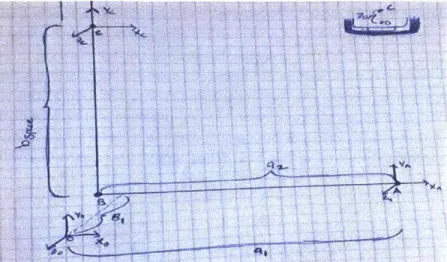
7.2.1 Form ulation of Hom ogenous Transfer M atrix... 38
7.2.3 New Fram e Configuration ... 49
7.3 New L-Fram e Configuration: Deflection Analysis ... 52
7.3.1 Double Integration M ethod and Virtual W ork... 52
7.3.2 Double Integration Analysis for L-Fram e M em ber 2 ... 52
7.3.3 Virtual W ork M ethod for L-Fram e M em ber 2 ... 53
7.3.4 Analysis of L-Fram e M em ber 1 Analysis ... 55
7.3.5 Conclusion from L-fram e Deflection Analysis ... 57
7.3.6.1 Stress Analysis on L Fram e M em ber 2 ... 58
7.3.7 L-Fram e M em ber Selection Sum m ary ... 60
7.4 C-Fram e Structural Analysis ... 61
7.4.1 Total system Force Balance ... 63
7.4.2 C-Fram e M em ber 1 Force Analysis ... 64
7.4.3 C-Fram e M em ber 2 Force and M om ent Analysis ... 65
7.3.4 C-Fram e M em ber 3 Force and M om ent Analysis ... 66
7.4.5 Evaluating the Stress in the C Frame ... 66
7.5 Fasteners: ... 68
7.5.1 Direct Shear calculation ... 68
7.5.2 Torsional Shear calculation ... 69
Okaine 8
7.5.4 Equivalent Stress and Failure Criterion:... 70
7.6 Calculations for Fasteners Connecting the Two L-fram e mem ber ... 71
7.6.1 Direct Shear:...72
7.6.2 Torsional Shear Stress:...72
7.6.3 Bending Stress...72
7.6.4Critical Stress/ Failure Criterion: ... 73
7.7 Calculations for Fasteners Connections for C-Frame... 74
7.7.1 Direct Shear:...75
7.7.2 Torsional Shear Stress...75
7.7.3 Critical Stress/ Failure Criterion: ... 75
Chapter 8 Platform M aterial Selection ... 76
8. 2 Cost Of Structural Fram e & Platform ... 82
Chapter 9 Total System Sum m ary...83
9.1 System Perform ance ... 84
9.1.1 Load Capacity...85
9.1.2 Linear Travel...85
9.1.3 Linear Speed ... 85
9.1.4 Vertical Height of the Platform M ount... 85
9.1.5 Total Platform W eight...85
9.2 Total System Cost...86
Conclusion...86
Appendix A ... 88
Q&A...88
List of Figures
Figure 1 Car Jack Platform... 12
Figure 2 Four Bar linkage ... 13
Figure 3 Proposed Lift Design ... 14
Figure 4 Overall Proposed Design ... 15
Figure 5 Critical Stresses in Leadscrew.[1]... 20
Figure 6 Image of Catilievered load provided by PBC linear_[2] ... 25
Figure 7 Small Sproket Speed vs. Nominal Power Required_[3] ... 32
Figure 8 Frame and Structure Cad Model... 35
Figure 9 Connecting Tube Assembly... 36
Figure 10 Free Body Diagram of Connecting Tube. ... 37
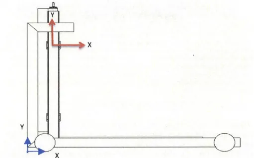
Figure 11 Reference Frame Definition of Platform Lift... 39
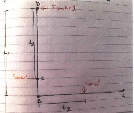
Figure 12 L -Frame Simplification...40
Figure 13 Initial L-Frame Design...47
Figure 14 Free Body Diagram of L-Frame Member 1...48
Figure 15 New L-Frame configuration ... 50
Figure 16 L-Frame M ember 1(New Configuration Free Body Diagram )... 51
Figure 17 Free Body Diagram of L-Frame member 2... 53
Figure 18 Free Body Diagram of L-Frame member 1... 55
Figure 19 Free Body Diagram of L-Frame member 1 with virtual moment applied to it ... 57
Figure 20 C Frame Diagram...61
Figure 21 Simplified Hand drawn C-Frame ... 62
Figure 22 C-Frame M ember 1 Free Body Diagram. ... 64
Figure 23 C-Frame M ember 2 Free Body Diagram ... 65
Figure 24 C-Frame member 3 Free Body Diagram ... 66
Figure 25 Fastener Pattern ... 71
Figure 26 Zoomed View of L-Frame Fastener Pattern ... 71
Figure 27 C-Frame Fastener Pattern Schematic ... 74
Figure 28 Deflection Result of Platform without Supports... 78
Figure 29 Stress Concentration Results for Platform without Supports... 79
Figure 30 Deflection Results for Platform with Supports ... 80
Figure 31 Stress Results for Platform with Supports ... 81
Figure 32 Frame of Platform Lift ... 83
Figure 33 Overall System Design...83
Figure 34 Amp flow M otor Technical Drawings_[4] ... 89
Figure 35 Leadscrew End Support Schematic_[5]...90
Okaine 10
List of Tables
Table 1 Values of Effective Length Based on End Constraints [6] ... 16
Table 2 Design Parameters of Lea dscrew ... 16
Table 3 Initial Leadscrew Parameters [7]... 18
Table 4 Variable Definition for Bearing Stress Calculation ... 20
Table 5 Cost Estimates for Leadscrew ... 24
Table 6 Variable Definition for Camroller Analysis ... 26
Table 7 Cost of Linear Guide System ... 27
Table 8 Com parison of Selected M otors... 27
Table 9 Variable Definitions and Results for Gear Radius Calculation... 28
Table 10 Gear Tooth Bending Stress Parameters ... 29
Table 11 Chain Drive Design Specifications ... 30
Table 12 Design Horsepower Requirement Summary... 31
Table 13 Summary of Horsepower Limits... 33
Table 14 Variable Definitions For... 34
Table 15 Connecting Tube Bending Stress Variables... 37
Table 16 Summary of Variables for Cam Roller Stiffness Calculation... 45
Table 17 Deflection Results of Initial L-Frame Analysis using the Double Integration Method ... 49
Table 18 Deflection Results of New L-Frame Configuration using the Double Integration Method...52
Table 19 Parameters and Results on L-Frame Dimension Optimization ... 58
Table 20 Summary of Variables used to Calculate Bending and Shear stresses in L-Frame Member 2...59
Table 21 Summary of L-Frame Member Dimensions and Associated Forces and Deflections ... 60
Table 22 Variable Definitions for C-Frame Analysis...63
Table 23 Summary of Variables for Stress Analysis of C-Frame Members...67
Table 24 C-Frame Member Selection Summary ... 68
Table 25 Summary of L-Frame Fastener Pattern Details ... 74
Table 26 Summary of L-Frame Fastener Pattern Details ... 76
Table 27 Material Properties Table for Platform Material Selection...77
Table 28 Total Material Cost of Platform...81
Table 29 Total Cost of Structural Frame and Platform ... 82
Table 30 System Perform ance Chart ... 84
Table 31 Platform W eight Distribution ... 85
Table 32 Total System Cost...86
Chapter 1 Design Problem
The Skywalker as found in MIT's Newman lab is a device that performs Body Weight Support Treadmill Therapy a form of walking therapy for recovering stroke patients. To achieve this it uses two independently moving treadmills that allow an individual to practice the walking motion. During clinical trials conducted in the fall of 2014, it became evident that the design of the Skywalker did not fully address how patients would mount and dismount the Skywalker. Currently, patients using the Skywalker must climb a set of steps to get unto the treadmill platform. Climbing the steps can be difficult for some patients and requires assistance from a therapist or helper. Difficulty mounting the Skywalker limits the demographic of patients the Skywalker can treat. The purpose of this design thesis is to design and implement a mechanism that will allow patients to mount and dismount the Skywalker with minimal assistance from a therapist. Through the design and implementation of such a mechanism, the Skywalker will be able to expand its impact in BWSTT to a larger percentage of the population affect by stroke related gait abnormalities.
Chapter 2 Design Specification
As defined before the intent of this thesis is to design a system that will allow patients with limit mobility to mount the Skywalker which helps to improve their mobility. The system that does this must satisfy the following, structural, cost, speed, geometric, and safety specifications.
2.1 Structural Specification
The current Skywalker is able to support a weight of 4501bs with a safety factor of 1.5. Thus the, intended use of the Skywalker system is for individuals between 0-300lbs. As a result of this parameter, any supporting accessories for the Skywalker that will support the user's weight must at a minimum support the weight of 4501bs. Unlike the Body weight support system, the system that will be designed must also support the weight of the walking aids that the user needs for mobility. Thus in order to determine the structural specification for this design, we must account for the weight of a wheel chair. Depending on the type of wheel chair he weight can range from 351bs for a manual Wheel chair to 260 lbs. for a powered wheel chair. Most manual wheel chairs however will range from 351b-75lbs. Thus if we add the maximum weight of 300lbs and the maximum wheelchair weight of 751bs, we find that the total weight the lifting system should hold is 5701bs. This includes a safety factor of 1.5. The combined weight of the material required to make platform and the patient and their corresponding wheel chair,
cannot exceed 1000lbs. A safety factor of 2 is also applied. Thus, the design of the system must be able to withhold 2000lbs of force.
2.2 Geometric Constraints
The device that will be design falls under a classification of systems known as platform lifts. These lifts must comply with ADA, and ASME standards. According to the ADAAG 4.2.4.2 the minimum floor space for the platform is 30"x48". Additional dimensions must be added for the necessary maneuverability conditions. In addition to the ADA standards that must be satisfied, the platform lift that is designed must have the ability to lift the patient 18" to the height of the Skywalker Treadmill.
2.3 Speed
The speed specification consists of two parts. The first part deals with the amount of time needed to lift the patient to the height of 18". The maximum amount of time to travel this length is prescribed to be 12 seconds. Thus the speed requirement for this system should be no less than .91 m/min. currently, the maximum speed of lift platforms are about 5.2m/min. Thus the maximum tolerated speed will not exceed 5.2m/min.
Okaine 12
2-4 Sifety
The platform lift that is designed must also be safe according to the ASME and ADA standards. Thus, the lift must have a side walls that are 42" high. This will allow for both standing and wheelchair bound patients to see over the sides as the platform is being lifted. Moreover according to ASME 18.1, these side bars must be able to withstand 105bs of force.
Chapter 3 Initial Designs Pursued
There were three major designs developed during the idea generation phase of this design. These concepts can be classified into two groups. There were concepts in which the body weight support of the current Skywalker gamma would move to allow for a patient to mount the system. The other class of ideas would involve having a separate platform to the current sky walker to allow for the patient to be
lifted to the final height of the Skywalker.
3, Et ded UM"dy WeighJ A Suoport Cncp
The extended body weight support concept involved increasing the travel of the current body weight support. The seat attached to the leadscrew assembly would be allowed to decrease in height until the seat was directly below the patient's trunk when standing at the base of the Skywalker. Then the patient would sit on the sit and be fastened in and the seat allowed to move until the patient's feet are above the height of the Skywalker. In order to achieve such a design, the entire body weight support system would need to move back to allow the patient to either wheel or walk to the seat and be lifted to the height of the Skywalker. What this mean however, is that once the patient is on the seat and has reached the desire height, the entire body weight support structure must be accelerated back to its original position horizontally. This means that the patient would also be accelerated. This has the potential to cause the patient to fall off the body weight support system while in transit. Moreover, there would be also being a lot of automation and possible railing systems needed that would further complicate such a system. Thus for mainly the issue of safety, this concept is eliminated from the design consideration.
3.2 Car
Jack
Platform
This idea was initially explored because of the existence of cheap and available technology that could be used to quickly prototype a design. A typical car jack is able to support about 1.5 Tons of weight. This exceeds the amount of force needed to support the patient and the platform. Moreover, the acme leadscrews used in these designs allowed for the system to not be back drivable since there was sufficient friction in the system. While promising, there were two major draw backs to such a design. The first is that upon thorough research of the existing products on the market, no car jacks were found that would be able to lift the platform the desired 18 in to the top of the Skywalker. Moreover, the load capacities of these scissor jacks were not constant. Rather, it was dependent on the overall height of the scissor jack. Thus, in their fully collapsed position, carjacks are not capable of holding the desired load of
8909N.
3.3 Four Bar Linkage
(
1,-1W60
ism
The Third idea is another variation of the separate platform concept. In this concept, the platform forms one of the legs of a four bar linkage. In order to be able to rise to the height of 18" the two vertical members of the four bar linkage must be 20 in long. On of these two members would have to be driven in order to cause the platform to raise and lower to the desired position. Like the scissor jack, the four bar linkage has the same problem in that in its collapse state an infinite amount of torque is needed in order to raise a desired load. Since no motor can provide such torque having such a design proposes a potential risk of not having sufficient power to drive the system. Moreover, given the kinematics of a 4 bar linkage, the envelope of the entire platform in this case would be larger. This is because as the leg of the four bar linkage is driven; the platform will translate both vertically and horizontally. This means that
Okaine 14
in the horizontal direction the platform will move past its 48" envelope and thus more space would be required for such a design. Thus, for these reason, the four bar linkage was also removed from consideration in this design due to the torque requirements and the power requirements.
3.4. roposed design
Leadscrew Mount
L-Frame Member 1
Connecting Bar bracket
Connecting Bar
L-Frame Member 2 Camroller
Leadscrew
Motor Mount
Figure 3 Proposed Lift Design: This figure excludes the platform and ramp in order to reveal the support components such as the L frame members, motor mount and connecting bar.
Okaine 15
iiY
V
Safety Rail Platform Ramp WheelFigure 4 Overall Proposed Design. This image demonstrates the rail the safety rail, wheels and ramp. The ramp will rise 7" inches in the air to help accommodate for the design
The actuation system constitutes of a leadscrew which is driven by a geared motor. The leadscrew is fitted with a flanged bronze nut that allows for the transfer of load generated by the leadscrew and geared motor assembly to the connecting bar. This connecting bar as illustrated in figure 3 is attached to the L- frame member #1 which is attached to the cam roller. The platform is attached to the L-member # 2 using L-brackets. The platform is made of an aluminum sheet below the platform there are three inch steel tubes that are used improve the stiffness of the sheet over all. Two figures have been provided for the proposed design. Figure 3 excludes the ramp and platform in order to provide an image of the L-frame and other components of the lift. Figure 4 provides an image of the entire design all together.
Unlike the other designs this method would require the least amount of actuation. Designing a leadscrew for vertical application allows for this design to achieve the desired travel which was not available for all the car jacks found during the research of that design. Moreover, the vertical motion of the nut on the lead screw eliminates the horizontal translation that was present in the four bar linkage design. This means that this design can have smaller foot print than the design for the four bar linkage. Finally the vertical geometry of the vertical leadscrew design allow for a more constant torque once the initial static friction is overcome. Thus, given that this design is able to address the potential draw backs of the ideas listed above, this design presents itself as the most ideal of the ideas presented. The remainder of this document will discuss the selection process for each components of the overall system.
Okaine 16
Chapter 4 Leadscrew Specification
From the previous sections it is evident that for his particular application the leadscrew among the ideas developed during the concept phase provided a more cost effect option compared to pneumatics, and hydraulic options. Moreover, the leadscrew option proposed a way to passively prevent the platform from back driving which is helpful in preventing unwanted drops of the platform. Unlike the two other systems, there is no possibility of leaks thus decreasing the possibility of catastrophic drops.
When designing a leadscrew, the diameter of the leadscrew is very important. The determination of the leadscrew diameter is characterized by the methods of failures his lead screw can experience. In his case the primary methods of failure is buckling and yielding of the cross-sectional area. Thus, the Euler buckling equations can be used. To do so, the critical load at the onset of bucking is designate to be 8909N. There are three methods of failure in a leadscrew assembly: buckling, yielding of the leadscrew at its cross-section, and shearing as a result of the force applied on the threads. The consideration of buckling and yielding are useful in the determination of the diameter of the leadscrew. The consideration of the shearing of the threads is useful in the determination of the pitch of the leadscrew.
4.1 Screw Diameter:
Using the Euler buckling equation, the diameter of the leadscrew is determined using equation 1
Ir2EI (1) [6]
Pcr = Le
Pcr is the critical load. For this design, the critical load is equivalent to the combined weight of the patient, their accompanying wheelchair and the weight of the platform with specified safety factor of 2. 'E' represents the young's modulus of the material selected for this design. 1020 steel is a typical material used to manufacture leadscrews and thus will be used in the formulation of this analysis [7]. Le represents the effective length of the lead screw. The effective length on the leadscrew is dependent on the end constraints of the leadscrew. A table 1 provides the end constraints and the corresponding values of effective length. Please note that L denotes the distance between the supports of the proposed design.
Table 1 Values of Effective Length Based on End Constraints [6]
End Constraints Effective Length for Actual Column Length L
Both ends pinned Le= L
One end Pinned, one end fixed Le=0.7L
One end fixed, one end free Le=2L
Both ends fixed Le=0.5L
'I' represents the moment of inertia of the cross-section. The moment of inertia is dependent on the diameter for members with circular cross-sectional area. Thus, the diameter of the leadscrew can be determined by rearranging equation 1. E, Pcr and Le were determined based on design requirements and are presented in table 2.
Table 2 Design Parameters of Leadscrew
E= 210 GPa Pcr=8909.1 N Le=.6096m
264PcrL2 1/4 (2)
D8909N 3
E
)
D8909N = 0.013m
While this is expressed as in equality here, it should actually be treated as an inequality since there the diameter specified would be the minimum diameter needed for the onset of buckling at the desired load. Thus, from the calculations given, the required diameter is within the range of 1/2" and 5/8". Most lead screw come in specific fractional quantities. Since the value calculated above is higher than Y" the next available diameter is the 5/8" screw.
4.2 Design for Yielding
To ensure that the leadscrew does not yield due to the compressive load, the radius is used to compute equation 3. Care should be given to ensure that the inequality is satisfied..
Pcr (3)
S A
cy = 350 MPa
Since the leadscrew has a circular cross-sectional area, the area (A) is equivalent to the area of a circle. If the yield strength of the leadscrew material is known, the corresponding diameter can be determined by manipulating equation 4.
Pcr 1/2 (4)
r > (--,
r 2.846 x10 -3
m
The diameter found is much smaller than the .013m diameter need to prevent buckling. Thus, the diameter determined from the buckling equation will be used to specify the diameter of the leadscrew. The standard thread/inch used for a 5/8" leadscrew is 8 and the corresponding pitch (p) is given by
equation 5. These parameters will be used as proposal for the design and modify based on the determined stresses on the threads.
lin (5) [7]
thread P=3.175 x 10³m
4.3 Torque Required to Raise/Lower Load
One of the important parameters that must be determined for this system is the amount of torque required to raise the desired load 18" from the ground. To determine this equation 6 is employed.
Okaine 18
(cos(On)
sin a + it cosTR = Pcrrp (Cs(On) Co s a + " a
)
+ 1crrclc(6) [7]
W is the combined weight of the entire platform material and weight of the patient. The variable a is the lead angle and 0 is the pitch angle. The pitch angle is determined by the shape of the threads. ACME screws will be used for this application. The pitch angle of an ACME screw is 14.50. The second term in equation 6 represents the torque generated by the friction of the thrust collar. For this application roller thrust collars will be used. Thus, the rolling friction coefficient due to the thrust collar can be neglected. rp is the pitch radius is given by equation 7.
rp = [7] (7)
[7]
rp = 7.144 x 10⁻³m
The lead angle (a) corresponding to the specified leadscrew was computed using equation 8 and a summary of
leadscrew
parameters are given in table 3.a = tan-_1 P (8) [7]
21rr
Table 3 Initial Leadscrew Parameters [7]
Leadscrew Parameters Values of Leadscrew Parameters
Lead .125 m/rotation
Lead Angle a= 4.406 deg
Thread Angle 0 = 14.5 deg
On = tan-'(tan O cos a)
On = 14.465 deg
Mean Collar Radius r,.= 0.254m
Collar friction coefficient PC = 0
Friction Coefficient pt = 0.34
For this design the leadscrew will be made of steel and the nut for the leadscrew will be made of bronze. Thus, the coefficient of friction is .3 as stated in table 3. When all of these values are substituted we find that the torque required to accelerate 8909N (2000lbs) from rest is 24.763 Nm with a
leadscrew
with 5/8" diameter.This is the initial amount of torque needed to accelerate the leadscrew. In this case the variable pt is introduced to represent the coefficient of sliding friction. litis substituted for into equation 6 in order to evaluate the torque required to raise the load. Equation 6 is reproduced as equation 9 and the variables in table 3 are substituted into equation 9 to determine the torque required to raise 8909N (2000lbs).Please refer to table 3 for the parameters to substitute into equations 9. It is important to note that the coefficient of friction used in table 3 is the sliding friction for bronze on steel when dry. Thus, the torque produced would be a conservative estimate of the actual torque required torque since
cos(O,) sin a + Ptdynamic cos a[7]
T+ = PcPrrcp -+ (cr9cPc
Tcos(6n) cos a + Ptdynamic sin a
TR
= 27.533Nm4.4 Torque Required to Lower the Load
-cos(On) sin a + ptt cos a (10) [7]
TL = Pcrr cos(On) cos
a +
pt sin a) + PcrcpcTL = 17.43Nm
It is important to mention that all the variables expressed in equation 10 were previously defined in table 3.
4.4.1 Self-Locking Conditions
To determine if this system is self-locking, the inequality in equation 11 is evaluated. If the inequality is true, then the system is self-locking. If it is not true, the system is over hauling and motor must
continually supply pa torque to resist the platform from moving downward as a result of gravity. The parameters need to evaluate equation 11 can be found in table 3.
lcos(L]) (11) [7]
.34> .068
From the results of the system, it is evident that this leadscrew application will be self-locking and thus, the motor will not have to continually provide a torque to maintain the height.
4.5 Critical Stresses
To ensure that the screw does not shear, the critical stresses of the leadscrew threads are calculated Figure 5 is provided to help illustrate the different stresses and location of stress on the leadscrew that must be considered in the critical stress analysis.
Okaine 20 AI A /
N
5. 7 'NN=~__Figure 5 [1] Critical Stresses in ure illustrates the different points on a screw thread and the types of stresses experienced at that point. Of the three points, points C is the most critical since it experiences the most combinations of stress and also located at a discontinuity which promotes stress concentration at that point. Whis roint C
r m
sth
si- e of the thr'ads, stress a- point A and point B help inform the calculation of tress at point C.From the figure 5 it is evident that the stresses at point C will experience the highest stresses, closer observation reveals that point C will experiences many of the stresses that also act on point A and B. Thus, the evaluation of the stresses at point A and B will aid the understanding of the stresses experienced at point C. To begin the bearing pressure CB, is evaluated in equation 13. Equation 13
provides the equation for the root radius. Table 5 provides the definition of the variables needed to evaluate equation 12 & 13.
P= - (12) [7] rr = - 2r -___ 0 2 rr = 6.35 X 10 -3m Pcr (13) [7] B (r _ rr2)ne YB = 41.7MPa
Ta~e4
vriaeDeome
foBering
tre CAICULaItionVariables for Bearing Stress Calculation
Effective number of threads in the engagement ne= 3 zone that carry the load
Major Thread Radius ro = .0079m
Pitch p
Critical Load Pcr
The allowable stress that is possible between on the screw is 2000 psi which is equivalent to 13.8 MPa. This recommendation is based on the assumption that the nut is a sleeve that is passing over the leadscrew thus acting as a bearing surface. According to the assumed limit, the current design exceeds the allowable stress thus failure would occur at point A. To redesign, the pitch can be increased to decrease the stress experienced at point A. alternatively, the outer diameter of the screw can be increased to help decrease the stress. Thus, the proposed diameter is increased to 1" since it will lead to a more significant reduction in stress the stress is then recalculated in equation 14 and its solution given. The following sections provide the calculations for the new specified dimensions of the leadscrew. Table
5 provides a list of all the necessary values need to evaluate the remainder of this section.
Variable Definitions For 1" diameter Lead Screw
Critical Load 8909N
Collar Radius rc =.0254m
Effective number of threads in the ne = 3
engagement zone that carry the load
Lead Angle a = 4.406 deg
Major Thread Radius ro= .0127m
Pitch p = 6.35 x 10-m
Pitch Radius r = 1.1 x 10²
Thread Angle 6 = 14.5 deg
0,,= 14.465 deg
cr (14) [7]
-~rf - r2)ne
q-u = 13.4MPa
4.5.1 Torque Required to Raise the Load
cos(6n) sin a + pt cos a (15) [7]
TRy = Pcr rp
(
I+
Pcrrcic (1)c7\cos(8n) cos a + I't sin a TR = 45.2 07 Nm
The torque calculated above is the initial amount of torque need to raise the load with the 1" diameter leadscrew.
4.5.2The Torque needed to lower the Load
TL = PCrrp (-cos(On) sin a + Ptdynamic cos a + Pcrrcltc (16) [7]
cos(O) cos a + Ittynamic sin a TL = 24.959 Nm
Okaine 22
The values above have defined the torque necessary to raise the load as well as lower the load. Moreover, from the torque necessary to lower the load we find that this system will not be self-locking. Thus, the motor must provide constant torque to counteract the motion or a braking mechanism will be
needed.
4.45.3 Self-Locking Conditions
To determine if this system is self-locking, the inequality in equation 17 is evaluated. If the inequality is true, then the system is self-locking. If it is not true, the system is over hauling and motor must
continually supply pa torque to resist the platform from moving downward as a result of gravity. The parameters need to evaluate equation 17 can be found in table 3.
lcos(D) (17) [7]
27r .34 > .092
From the results of the system, it is evident that this leadscrew application will be self-locking and thus, the motor will not have to continually provide a torque to maintain the height.
4.5.6 Critical Point B
At this point what we are most concerned with is yielding and fatigue. Moreover, at point B, the material experiences torsional shear from the load being raised, traverse shearing and direct stresses on the root diameter. We will begin by computing the torsional shear stress that the screw experiences. This would be evaluated using equation 18.
2
TRrr (18) [7]
= rr
Ts = 93.8MPa
Note that in the original equation it is actually a difference between the torque required to raise the load and the torque to overcome the collar friction. However, given that the collar has a rolling element, the torque needed to overcome the friction is negligible and thus, it is neglected in this calculation. The direct stress experienced is essentially the weight that the thread must support divided by the root diameter of the lead screw. Thus the direct stress is expressed by equation 19.
3Pcr (19) [7]
Udir
-Odir = 93.8 MPa
Finally there is traverse shearing that a tooth experiences. This is calculated by assuming that the tooth of the leadscrew is a cantilevered beam. The calculation for this is as followed:
3 Pcr (20) [7]
Trmax =21rrr (1) ne Trmax = 46.9 MPa
It is assumed that the fatigue endurance limit for the 1020 steel that will be used in this case is approximately, half of the ultimate tensile strength of steel. This is however, not the expected fatigue strength that one should expect in this case. What should be expected is a fraction of these values. The
expected fatigue limit is dependent on multiple factors that further reduce the expected fatigue limit for the desired application.
The stresses at point C will govern failure. This is because there is a geometric discontinuity that would lead to stress concentration in this region. However, the formulation and the solution of the stress in region B and it will allow for solution for the stresses at point c to be calculated more efficiently.
At point c the only other stress introduced is the stress that occurs as a result of bending caused by the load being carried. The moment in this case is the product of the weight of the platform and the moment arm which is the difference between the root radius and the pitch radius. The flexure equation is used to analyze the stresses as a result of the moment experienced by the beam (thread).
12Pcr(r - rr) (21)
Ub = L2
Tnrrne k) ordi = 187.5 MPa
The stress concentration factor the screw geometry is not accurately determined as for other geometries. However, in one publication, it was determined that the stress concentration for screw threads can range between 2.7 and 6.7 [7]. A value of 3 was used for all the principle direction. With this in mind, it is important to remember that the potential methods for failure at point c will be yielding and fatigue, since the leadscrew will experience cyclical loading.
To determine the allowable fatigue we must determine the fatigue stress concentration factors that will be used in this case. Given that there are two tensile loads and one torsional load, the highest value of safety expressed in the equations below in order to find the corresponding constants to use in the calculation of the stress in this case.
Kfb = 0.65 x (3 - 1) + 1 = 2.3
Kfb = Kfd
Kfs = 0.70 x (3 - 1) + 1 = 2.4
Since cyclical loading is expected the alternating and mean stress the tooth will experience are calculated. To construct the right formulation for the cyclic load we recognize that in both the lowering and the lifting of the weight exerted on the threads does not change. However, the direction of the force does at point C. Thus, the stress experience at point c should be the same in magnitude for both lifting and lowering. Thus we can calculate the alternating stress for each case. Then we can plug these stresses into the Von mises stress equation in order to determine if yielding will occur. 0
za, Oxa,Twa refer to
stresses in the principal basis.
aza = Kf b (Udir 2 = 215.7MPa (22) [7]
Oxa = Kfd(a )2 = 431 MPa (23) [7]
Tyza = Kfs (S T)2 = 26.9 MPa (24) [7]
ya = 0 pSi (25)
T
xza 0 psi (26)
Txya = 0 psi (27)
Once the lead screw is specified, we can now approximate the power needed by the system and find the motor needed for this design. Note that k- is only used when one is concerned with the infinite life of the part. If k. is neglected then the main objective would be to see if at any point, the stress experienced by the tooth will exceed the yield strength of the material. If the equivalent tensile strength
Okaine 24
is below the desired value for yielding, we find that the material will have a high cycle capabilities. However, the cycles at this present state is not satisfied
Ceqc = X [(Uxa - ya + (uya - Uza + (Uza - Uxa)2] + 3(Txza2 + Tyza2 + Tzza2) (28) [7]
aeqc = 376.461MPa
The proposed steel needs to be of a grade that has a yield strength that exceeds the value given. Thus, a new material must be picked as an alternative to 1020 steel. However, the new material will in general not affect the expressed calculations above.
4.6 Cost of Lead Screw:
Given the requirements for the leadscrew, price quotes from the Nook industries, Thompson Linear motion and Joyce motions were requested. In all of the cases it was assumed that the end machining and end supports for the leadscrews will be all done by the specified companies. Table 5 gives a summary of the leadscrew specifications and cost estimate.
Table 5 Cost Estimates for Leadscrew
Company Name Nook Industries Thompson Linear Joyce Dayton
Motion
Product Number 104- SRA1004 CTL 24"
RA/BN/BK/31.30/20104/FS BN1004
BK-BK end supports
End Machining Yes Yes Yes
End Supports Yes Yes Yes
(included?)
Torque required to 23.7 Nm 24.9 Nm 21.9 Nm
raise the prescribed load
Maximum Dynamic 2.2241 x 10' 8.452 x 10³ N 2.2241 x 10'
Load
Total Cost of Assembly $1176.23 $1151.86 $2107.52
From table 5, it is important to recognize that the best leadscrew assembly for this application is provided by Nook industries. Although it is more expensive than the Thompson Linear screw, it requires less torque to raise the same amount of load. A lower required torque to raise the load means that for a given motor that would be used to drive the leadscrew, less power and greater efficiency can be achieved. Moreover, the leadscrew assemblies provided by Nook industries are able to sustain a dynamic load that is 3 times the maximum load. The leadscrew provided by Thomspon linear does not meet the design specifications of holding 8909N dynamically and thus for such reasons it is no longer consider a viable product for this application.
Chapter 5 Linear Guide System
While the leadscrews provide the force and the required motion for the lift, it is not the only aspect of the linear motion system. Cam rollers and profile rails are utilized in this design. Their main purpose in this design is to first facilitate linear motion. The rails associate cam rollers and linear guides ensure that any structure attached to these guides or the roller will continue to move in the desired direction. Moreover, the cam rollers and the profile rail bearings also aid in resisting moments in the structure. The forthcoming sections will give a brief overview of both cam rollers and profile rail bearings. It will then propose which one is best used for this application.
5.1 Cam Rollers vs. Profile Rail Bearings
The Hevi-rail cam rollers provided by PBC linear have the capability of handling loads up to a total of 4.6 tons using a standard rail. The fixed/adjustable bearing allows for the ease of alignment. PBC provides the option of welding mounting flanges to the cam roller. These welded flanges attached allow for the ease of mounting a platform to the system. Since both the profile rail and the Hevi-rail have ways of attachment, easy attachment to the system is not a metric to use to rule out one option over another. One important aspect to note is that in order for the Hevi-rail system to have a similar moment capacity as the regular profile rails, the system must have two rollers separated by a fixed distance. This is best depicted in figure 6.
P
AI
A I
Figure 6 Image of Catilievered load provided by PBC linear This image given by PBC linear illustrates the application of the Hevi-rail system in cantilevered loading conditions. Four rollers are used: two on each side. This configuration as mentioned before, allows the Hevi-rail solution to counteract the moments generated by the cantilevered load.
[2].
Unlike Cam rollers that require 2 cam rollers on each rail in order to counter act a moment, Profile rail bearing can support moments with the use of only one bearing block. All three companies presented in table 7 provide profile guide rails. However, upon technical recommendation from the individuals at PCB Hevi-Rail was the technology consider from PCB and not their profile rail guide product line. For the current design as seen in this discussion, cam rollers will be utilized. Since the potential of misalignment loads are less forgiving in profile rails vs. cam rollers. The prices for the profile guide rails from Thompson linear and Nook industries are provided in table 7. The selection of the linear guides from Thompson linear and Joyce Dayton was determined from the moment calculations in the Frame and
Okaine 26
5.2
Selection of Cam roller
The selection of the appropriate roller in such a configuration is motivated by the maximum amount of force that the each roller will experience in this situation. Q represents the load applied to the system. The distance L is the distance from the applied load to the suspension point. The variable P is the suspension point or, the location of the cam rollers. The variable A, is the distance between two bearings on the same rail. For this application
Q,
L and A are specified in table 6.Table 6 Variable Definition for Camroller Analysis
Variable Value
Applied Load(maximum including a safety factor of 2) Q= 8909N
Distance to the Suspension Point L= 914.4mm
Bearing Distance A= 609.6 mm
Equation 23 can be used to determine the radial loads that a cam roller will experience in order to resist the moments generated by the cantilevered load. The values of the variables used in equation 23 can be found in table 6.
Q * L (29) [21
Fmaxradal = 2
9A Fmax,radial = 6682N
After evaluating equation 23, it was determined that the maximum radial loads that will be experienced using cam rollers as demonstrated in figure 6 would be 6682 N. It is important to note however that this is only a preliminary result. Further structural analysis revealed that the deflection that the L-frame will experience will further load the cam rollers. Thus, the cam rollers that must be used for this application is HVB-062. This cam roller has the capability of withstanding 33.9kN of radial force. This is sufficient to support the moments generated by the cantilevered load in this application. In addition to selecting this roller, a welded flange is added to it. This takes away from possible machining time that would be necessary to fabricate an attachment device for the entire rail system.
5.3 Fixed vs. Adjustable Eccentric Bearing:
While discussing the Hevi-Rail system, it is important to introduce the Adjustable Eccentric Bearing feature that is available for the Hevi-Rail cam rollers offered by PBC linear. The eccentric bearing allows the ability to preload the rollers for the application of axial forces on the system. In this application, the system will utilize the radial force capability of the cam roller. Thus the fixed bearing option can be
utilized as opposed to the adjustable bearing option.
5.4 Linear Guide System Cost
When selecting a linear guide system, there are two major elements that often dictate the cost: the cost of the cam roller or profile rail bearing, and the cost of the associated rail. The rails for this system are a
total of 1016 mm long each. Table 7 outlines the cost of different compares the cost of cam rollers, and profile rail bearings.
Table 7 Cost of Linear Guide System
Solution Type Cam Roller Profile Guide Rails Profile Guide Rails
Company Name PBC Linear Thompson Linear Nook Industries
Product Numbers HVB-062/HVP4 5111H45B0
NHRC45FLS1ZCVCN-610L-(Roller with welded flanges) (Profile Rail Guide) 43-43S
HVR-5 X 1016 mm (Rail) 521H45A+610 (a complete profile guide (Profile Rail) rail assembly.)
Cost of Rails $168 x2 $286.70 x2
Cost of Guides/ $224.23x 4 $304.11 x2
Rollers
Total Cost $1233 $1181.62 $851.02
Chapter 6 Motor Specification
Based on the selection the leadscrew in section 4.6, the accompanying motor must be will be able to provide the necessary torque of 23.7 Nm to lift the platform. While the evaluation of the leadscrew provides the torque requirement, the speed and the power requirements are yet to be determined. Given that the pitch of the leadscrew is 6.35mm, it is evident that in order to raise the platform .4572m in the desired 12s, the motor must have an angular velocity of 360 RPM. With the speed now specified for this system, it is possible to select a motor for this application. Table 8 provides a summary of the prices and motor specifications of various proposed motors.
Table 8 Comparison of Selected Motors
NEMA 56 Dual Base DC-Geared Motors TENV Ampflow motors
Power 1 hp 1/4 1/6 1.0
Requirement
Voltage 24VDC 90 VDC 12 VDC 24 VDC
Requirement
Output Torque 3.95 Nm( 35-in-lbs) 17.5lNm(155in-lbs) 1.35Nm (12 in-lbs) 86.4Nm (770in-lbs)
Output RMP 1800 83 700 680
Gear Reduction 4:1 n/a 12:1 n/a
Supplier McMaster McMaster Grainger Ampflow
Okaine 28
Upon research it was determined that the amp flow geared motor is desirable for its price, and torque and speed capabilities. Moreover, this motor already comes with the gear reduction necessary to generate the required loads to drive the lead screw. Thus, the selection of the Amp Flow motor removes the need for the designer to create a gear reduction. I
6.1Gear Stress Analysis:
In order to allow for power transmission from the motor to the leadscrew, it was propose that mating of gears should be used. To properly choose the gear size for this application, the stresses on the gears must be analyzed to ensure that they do not yield while under load. In order to perform the stress analysis a pitch must be proposed. This pitch is used to determine of the diameter of the gear. Moreover, using the formulation of the gear tooth as a cantilevered beam, the stress on each individual gear tooth can be approximated.
6.1.1 Gear Radius Calculation
To begin the stress analysis of the gear, the diametric pitch is determined to be 12 for its initial assumption. Using the equation 24 described below, we are able to determine what the radius of gear 1, and gear 2, respectively. In order for meshing between gears to be possible, the gears must have the same pitch. Thus, both gear 1 and gear 2 have the same pitch. Table 9 provides the definition of the variables need to evaluate equation 30 for both gear one and gear two. In addition, table 9 provided the values of the radius of gear 1 and gear 2 as a result of evaluating equation 30.
N1 (30) [8]
2Pd
Table 9 Variable Definitions and Results for Gear Radius Calculation
Number of Teeth for Gear 1 N1 = 12
Number of Teeth for Gear 2 N2 = 12
Pitch Diameter P= 12 in-1
Radius of Gear 1 r= 0.5 in
Radius of Gear 2 r2= 0.5 in
6.1.2 Face width Calculation
The face width which is necessary in calculating the stresses is bounded between 9/Pd and 14/Pd. For this
design, a midrange value is chosen. However, these calculations will change once the parts have been determined and purchased. Thus, for the preliminary estimates, b (face width) will be 11.5/Pd. The face width is calculated in equation 31.
11.5 (31) [8]
Pd
b = 0.958 in
The value for the face width determined in equation 31 is the minimum face width for the specified pitch. One should recognize however that the face width evaluated here is only an estimate. The final face width of the gears selected will be determined by the gears selected in this design.
6.1.3 Gear Tooth Stress
The flexure equation expressed in equation 31 is used to evaluate the bending stresses that the gears will experience. Equation 32 provides a modified version of the flexure equation for gear teeth.
6M (32) [8]
6Ft1Pd (33) [8]
bY12
The variable Y in equation 33 is the Lewis form factor that is determined empirically and is dependent on the number of teeth a gear has. The Lewis form factor for various form factors has been tabulated. For this application, the Lewis Form factor is .245. In order to determine the tangential force (Ff1) the torque
the motor would supply must be utilized. The torque generated by the motor and the gear radius are substituted into equation 34 in order to find the tangential force. Table 10 gives a summary of the calculated values for equations 33 and 34.
TR (34)
Ft 1 = =16r-- 1
Table 10 Gear Tooth Bending Stress Parameters
Gear Tooth Bending Stress agbi = 35.61 MPa
Lewis Form Factor Y1 = .245
Tangential Force Ft1 = 74.919N
Given these requirements for the gears it was originally proposed that the McMaster 201 Pressure angle spur gear with a pitch of 12 and 21 teeth and a face width of 1" is sufficient for the application. The cost of each individual gear on McMaster Carr is $33.45. Thus the total cost of the gearing for this system is $66.90.
6.2 Chain Drive
With the current design, the distance between the motor shaft and the leadscrew would require the use of large gears which would increase the cost of the system. As a result a chain drive design is employed in the place of the standard gear mates. Typically a chain in particular a roller chain will fail as a result of fatigue. This is due to the fact that the tensile forces on the chain fluctuate between high loads on the tight side and low loads on the slack side. While fatigue is the dominating mode of failure in a chain drive design, which the operating speeds of the chain drive also affects the types of fatigue experienced. At low speeds, link plate fatigue dominates the system. When the operating speed is high, bushing fatigue will dominate the failure of the system [9].
In order to select the appropriate chains, empirical equations have been developed. These empirical equations provide the horse power limits that the system must not exceed in order to prevent the different forms of failure mentioned above.
Okaine 30
Equation 35 demonstrates the horsepower limit that a system must satisfy in order to prevent link plate fatigue. Equation 36 describes the horse power limit in order to prevent bushing fatigue. Finally equation 30 represents the horse power limit in order to prevent excessive wear or galling. Equations 35, 36, and 37 correspond to equations 17-21, 17-22, and 17-23 respectively in Mechanical Design of Machine Elements and Machines book written by Collins, Busby and Staab.
(hpuim)ip = KjpN,.08n.9p(3.O-.07P) Kip= .0022 for #41 chain (35)
= .004 for all other chain number [9]
1000KrbNj5sp8' N,- # of teeth in smaller sprocket (36)
(hplim)rb - 1s n,- rotational speed of the smaller sprocket [9]
(hP(im)s nspNs /110.84) (4.413 - 2.073p p- chain pitch (37)
Krb = 29 for chains # 25 and #35 [9]
- 0.02 7 4NL) = 3.4 for all other chain #4
- (In
)
(1.59 log p + 1.873) 17 for chains # 40-2401000 NL- # of teeth in larger sprocket
nL- rotational speed of the larger sprocket
It is important to recognize that when a designing a chain drive system, one must make sure that the system's horse power does not exceed any of the calculated horse power limits outlined above. In the sections to follow, a method used to select the chain, and sprocket as outlined by Collins, Busby and Staab in chapter 17 is presented.
6.2.1 Chain Drive Design Specifications
The first step in the process is to determine the design specification of the system. Included in the design specifications are power requirements, the input shaft speed, the output shaft speed, the allowable speed fluctuation, the shaft center distance, and the desired safety factor. The table 11 presents a summary of the design requirements for this system.
Table 11 Chain Drive Design Specifications
Power transmitted .8 hp
Input Shaft Speed 500 rpm
Output Shaft Speed 416 rpm
Allowable Speed Fluctuation 5%
Shaft Center Distance .127(m)
Safety Factor 2
Life Requirements
6.2.2 Evaluating Design Horsepower Requirements
Once the system requirements have been specified, the next step is to determine the design horse power requirements. This is done by utilizing equation 31 which corresponds with equation 17-24 in Collins, Busby and Staab.
Ka(hp)nom Ka-application factor (38) [9]
Kst (hp)nom- nominal power required,(horsepower) K5t-Multi-strand factor
The design horsepower requirement is power specification that the system should be designed for. The application factor Ka , is used to account for the shock and impact loading characteristics of the driver of the chain. In this design, the driver is an electric motor. Moreover, it is assumed that there will be uniform motion in the system and nominal amount of shock. Thus, using Table 17.2 in Collins, Busby and Staab's text the application factor of 1 is selected for the evaluation of equation 38. Kt represents what is known as the multi-strand factor. In general as the number of chain strands used to drive the system increases, the horse power requirements decrease. In the case of this design it is initially determined that only one chain will be used in this design. A summary of the specified quantities and the calculated value of the design horsepower requirement are given in table 12. To determine the nominal horse power required, the power transmission requirements from the table 11 is substituted into equation 31. This yielded that the nominal power requirement was .8 horsepower.
Table 12 Design Horsepower Requirement Summary
Application Factor Ka-1 Assumed nominal amount of
shock and uniform motions.
Multi-strand Factor Kst-1 Only one strand is used.
(hp)nom- nominal power .8 hp
required,(horsepower)
Design Horse Power (hp)d = .8(horsepower)
Requirement
6.2.3 Initial Chain Selection Estimate
Once the design horsepower requirement is determined, an appropriate chain pitch was selected using the calculated value of the design horsepower. Figure 17.14 provided by Collins, Busby, and Staabs is used to determine the pitch. This graph plots the nominal power requirement vs the speed of the small sprocket in rpm on a log-log scale. Lines for different chain sizes are fit on this plot. In this design, it was determined in the motor specification that the small sprocket speed would be equivalent to the input shaft speed of 360 rpm and a total power of .8hp. When plotted on this chart it is determined that the appropriate chain size is within the regime where # 35 chains are used. Figure 7 provides an image of the chart used for this analysis is presented in the figure below.
Okaine 32
Figure 7 [3] Small sproket Speed v, -.propriate sprocket speed, nominal power requirements and the appropriate chain selections for those conditions. In this design it was determined earlier that the small sprocket speed Would be equivalent to the input shaft speed of 360 rpm and a total power of .8hp. when plotted on this chart it is determined that the appropriate chain size falls within the regime where number 35 chain is used.
Given the initial guess at the chain size, Table 17.6 given by Collins, Busby and Staab was consulted in
order to ensure that that the minimum distance between the two shafts was conserved. After consulting the table it was determined that the center distance had to be increased to 152.4 mm in order to accommodate for the desired chain size.
62A eterninaionofsi 01i a1nd ag spr;ktTei on
Once the Chain size and the distance between the shafts were determined, the number of teeth of the small sprocket was selected. Once again a figure 17.13 as given by Collins, Busby, and Staab was consulted in order to get an initial estimate. This graph illustrated a relationship between the number of teeth on a sprocket and the associated fluctuations in the speed of the system. Since the desired speed fluctuation was 5% it was determined that a sprocket with 15 teeth could be best utilized for this system.
Upon determining the number of teeth for the smaller sprocket the relationship between the input shaft speed and the output shaft speed is used to determine the required tooth count for the large sprocket. Given that the input shaft speed will be 500 rpm. The desired output shaft speed is 360 rpm. In order to achieve this, larger sprocket (driven sprocket) must have 18 teeth to achieve a final speed of 416 rpm.
With the specified values outlined above, the limiting horsepower will be calculated in order to ensure that chain is designed to prevent failure. An outline of the calculated values and the necessary variable definitions are presented in table 13. Please note that equations 35,36, and 37 are employed in order to calculate the Horse Power limits.


![Figure 5 [1] Critical Stresses in ure illustrates the different points on a screw thread and the types of stresses experienced at that point](https://thumb-eu.123doks.com/thumbv2/123doknet/14687996.560613/20.918.278.601.126.511/figure-critical-stresses-illustrates-different-points-stresses-experienced.webp)
![Figure 7 [3] Small sproket Speed v, -.propriate sprocket](https://thumb-eu.123doks.com/thumbv2/123doknet/14687996.560613/32.918.223.670.167.464/figure-small-sproket-speed-v-propriate-sprocket.webp)