Design and Manufacture of a Modular Cylindrical Apparatus for
Ferrofluid Experimentation
by
Katrina Leigh Schoen Submitted to the
Department of Mechanical Engineering
in Partial Fulfillment of the Requirements for the Degree of
fMvASSACHUSETTS
INSTITUTE OF TECHNJOLOGYOCT20 2011
LiBRARIES
ARCHIVES
Bachelor of Science at theMassachusetts Institute of Technology June 2011
© 2011 Katrina Leigh Schoen All rights reserved
The author hereby grants to MIT permission to reproduce and to distribute publicly paper and electronic copies of this thesis document in whole or in part in any medium now known or
hereafter created. Signature of Author... .. ...
Department of Mechanical Engineering May 6, 2011 Certified by/
Accepted by...
Markus Zahn as and Gerd Perkins Professor of Electrical Engineering is Supervisor .
... ... .. .... ... .... ... ... ... ...
Samuel C. Collins Pr Mechanical Engineering
Design and Manufacture of a Modular Cylindrical Apparatus for
Ferrofluid Experimentation
by
Katrina Leigh Schoen
Submitted to the Department of Mechanical Engineering on May 6, 2011 in Partial Fulfillment of the Requirements for the Degree of Bachelor of Science in Mechanical Engineering
ABSTRACT
Ferrofluids, colloidal suspensions of coated magnetic nanoparticles inside a carrier fluid, respond to externally applied magnetic fields. This thesis addresses the behavior of these fluids when subjected to an azimuthally rotating uniform magnetic field. In order to test the theory that fluid flow in this situation is driven by non-uniform magnetic properties originating from container shape, it is necessary to test ferrofluids in cylindrical vessels of varying aspect ratio. A stacking modular solution was designed and constructed to provide the proper apparatus for these tests. Experiments were conducted to investigate fluid flow patterns, and initial results indicate support for the theory of non-uniform demagnetizing effects as the cause of fluid flow in cylinders of finite height.
Thesis Supervisor: Markus Zahn
Acknowledgements
I would like to thank Professor Markus Zahn for the opportunity to work on this very engaging project, as well as his support throughout its progress.
I am greatly indebted to Dr. Shahriar Khushrushahi for his generous contribution of time and guidance in the completion of this thesis.
Many thanks to Ken Stone of the Hobby Shop and Pat McAtamney of the Laboratory for Manufacturing and Productivity, who provided helpful input and machining instruction during the design and manufacturing stages of the project.
Thanks to Michael Snively for offering invaluable advice, help with laser cutting at the Product Design Laboratory, and amicable company in Building N 10 while working on his own ferrofluids thesis.
Finally, I would like to thank my family and friends, without whose support and love I would never have reached this milestone in my undergraduate education at MIT.
Table of Contents
1. Introduction to Ferrofluids...1
1.1 Ferrofluids ... 1
1.2 Behavior in a Uniform Rotating Magnetic Field...1
2. M odular Cylindrical A pparatus... 2
2.1 Requirem ents... 2
2.2 Design Iterations... 4
2.2.1 Initial Design and Fabrication: Stacking and Sealing ... 4
2.2.2 Secondary Design: Incorporation of Ultrasound Probes... 8
2.2.3 M odifications for Manufacturability ... 9
2.3 Final Designs ... 13
2.3.1 Large Cylinder... 14
2.3.2 Small Cylinder... 17
2.3.3 Fluxball Fixture... 20
2.4 Final Manufacturing Process... 21
2.4.1 Cylinders...21
2.4.2 Fluxball Fixture... 24
2.5 Results ... 25
3. Experim ental Design ... 28
3.1 Fluid Properties ... 28
3.2 Ultrasound... 28
3.3 Fluxball ... 29
3.4 Data Collection Process... 30
3.5 Data Processing... 31
4. Experim ental Results ... 33
4.1 Short Cylinder... 33
4.2 Tall Cylinder ... 35
4.2.1 Top Region ... 36
4.2.2 Middle Region ... 38
4.2.3 Bottom Region ... 40
5. Conclusions and Continuation of W ork ... 42
References...44
A ppendices...45
Appendix A: Mechanical Drawings, Large Cylinder... 45
Appendix B: Mechanical Drawings, Sm all Cylinder ... 50
Appendix C: Mechanical Drawings, Fluxball Fixture ... 55
Appendix D: LabView Fluxball Control Program ... 59
Appendix E: Part List ... 60
Cylinders ... 60
Fluxball Fixture...60
Appendix F: Full Raw Data Set... 61
Short Cylinder ... 61
Tall Cylinder...63
Appendix G : Additional Data Set ... 68
Processed Data ... 68
1. Introduction to Ferrofluids
1.1 Ferrofluids
Colloidal ferrofluid is a synthetic liquid consisting of suspended ferromagnetic or ferrimagnetic nanoparticles in a carrier fluid. The particles are on the order of 10 nm in diameter, small enough to be dispersed in the fluid through thermal agitation and Brownian motion. A surfactant coating is also used to prevent clumping among particles; the surfactant chains are on the order of 2 nm in length (Figure 1). Due to the presence of these particles, ferrofluid responds to an applied external magnetic field. With its relatively low concentration of nanoparticles, colloidal ferrofluid also maintains liquid flow properties when subjected to a magnetic field [1]. Within a moving magnetic field, ferrofluid exhibits interesting behavioral properties that have become the subject of recent investigation.
Figure 1: Magnetic nanoparticles coated in surfactant, typical of those suspended in colloidal ferrofluid [1]
1.2 Behavior in a Uniform Rotating Magnetic Field
When ferrofluid in a covered cylindrical container is placed inside a uniform, rotating azimuthally directed magnetic field, the fluid undergoes "spin-up" to bulk rotational flow. Possible explanations for this observation include spin diffusion theory and flow driven by non-uniform magnetic properties. In support of the latter theory, experiments have shown that demagnetizing effects caused by non-uniformity in container shape are responsible for spin-up flow in ferrofluids [2].
The internal magnetic field experienced by a fluid body is the result of the externally applied magnetic field and demagnetizing factors based on body shape. As a result, for a uniform external magnetic field, the internal magnetic field is uniform only for ellipsoidal bodies such as spheres and infinitely long cylinders. Correspondingly, in previous experiments conducted with spherical containers, negligible flow is observed in the fluid (less than 1 nm/s in velocity) [3]. For a cylindrical container of finite height, however, the bulk spin-up described above has been observed.
2. Modular Cylindrical Apparatus 2.1 Requirements
In order to further investigate the behavior of ferrofluid in a uniform rotating magnetic field, particularly the theory of flow driven by non-uniform internal magnetic field, it was determined that a new set of ferrofluid vessels would be required. In particular, tests would be performed in a set of partial spheres and a set of cylinders, each with various heights. This thesis focuses on the problem of cylindrical vessels. The coordinate system used to refer to the cylinders is presented in Figure 2 below.
Z
r
...
Figure 2: Cylinder with coordinate axis; second view is from the top. Relevant
coordinates are along the axis of the cylinder (z), radial direction (r), azimuthal direction (phi), and x-direction
To examine the role of demagnetizing effects on bulk fluid flow, it is necessary to test cylindrical containers of both large and small height-to-diameter aspect ratio. For the low aspect ratio case, demagnetization effects lead to a non-uniform internal magnetic field even when the applied external field is uniform. If these non-uniform effects are responsible for driving flow, therefore, velocities in the small aspect ratio case should be relatively large. The flow pattern may or may not be be non-circular, including flow in the z-direction.
For the high aspect ratio case, demagnetizing conditions should approach those of an infinitely long cylinder; if the azimuthally rotating applied magnetic field perpendicular to the cylinder axis is uniform, the internal magnetic field will be uniform near the center of the cylinder height but not at the ends. According to the hypothesis being tested, then, bulk flow will differ between the ends and the middle of the long cylinder. More specifically, the ends of the cylinder will exhibit flow of large magnitude due to non-uniform properties in those regions. Again, the flow pattern may or may not be be non-circular, including flow in the z-direction. The middle portion of the cylinder may exhibit small flow due to the presence of spin diffusion or due to driving forces from the top and bottom of the cylinder. If flows are circular, velocity in the phi direction will have a significant magnitude, and velocity in the radial and z directions will be close to zero. In order to test the non-uniformity hypothesis, therefore, it is necessary to directly measure or calculate fluid flow in the radial, azimuthal (phi), and z directions.
Considering the dependence of fluid flow on cylinder aspect ratio, a modular design was desired to facilitate testing with various cylinder heights. It is necessary that the cylinders completely seal to prevent leakage of ferrofluid, for both oil-based and water-based versions. Furthermore, it must be possible to fill the container with ferrofluid and eliminate any traces of air. To whatever extent possible, the inner surface of the container should be smooth, with the shape of a perfect cylinder.
The container also requires appropriate features for inserting and securing ultrasound probes, which are used to measure fluid movement (Figure 3). The four probes to be used are UDV transducers made by Signal Processing; their mechanical characteristics are presented in Table 1 below.
Rodltput
8 -12 mm
30 mm
Figure 3: Ultrasound probes used to measure fluid movement. Three probes are of the first type; one probe is of the second type [5]
Table 1: Ultrasound probe mechanical characteristics
Probes 1,3,4 Probe 2
Case diameter (measured) 8.2 mm 8.2 mm
Case length 10 mm 30 mm
Output wire style Radial Axial
Case material Epoxy Epoxy
It must be possible to affix the ferrofluid-filled cylinder into the experimental fluxball apparatus, which provides the uniform rotating external magnetic field (Figure 4). Finally, due to the magnetic experimentation, no components of the design may include any metal or magnetic material other than the ferrofluid. It was decided that two sets of containers would be designed, with respective inner diameters of 2 cm and 4 cm.
Figure 4: Isometric views of inner portion of the fluxball, used to generate uniform rotating magnetic fields
2.2 Design Iterations
2.2.1 Initial Design and Fabrication: Stacking and Sealing
Following determination of the design requirements and initial concept development, it was decided that the vessels would be made of stacking disks with sealing achieved through o-rings at each interface between disks. Assorted o-rings sets, providing a range of ring diameters in standard metric sizes, were obtained for initial prototyping and optimization; these ranged in thickness from 3 to 4 mm. The o-ring material was Buna-N (nitrile), chosen for its sealing capabilities for both oil-based and water-based fluids.
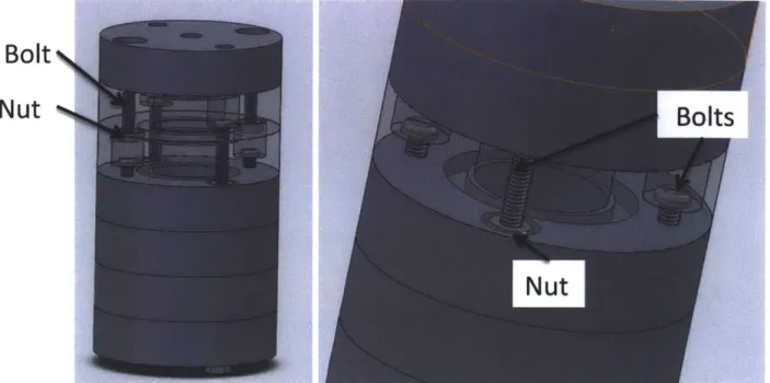
The vessels would be assembled using an alternating pattern of screws in four bolt holes surrounding the o-ring; these holes would be counterbored to allow fitting of the bolt head and
nut. SolidWorks models of this initial concept are pictured in Figures 5-6. This design would
allow for stacks to be removed individually with the rest of the vessel remaining rigidly assembled. An alternating bolt pattern eliminated the need for an excessively deep counterbore.
O-ring
groove
Bolt holes
Counterbore
Figure 5: Isometric (left) and top view (right) of initial design concept for stacking disks. Inner diameter is 2 cm; outer diameter is 2"
Bolt
NNut
Figure 6: Initial design concept assembly. Transparent portions display hardware attachment
The initial concept was designed for the small cylinder version, with a 2 cm inner radius. Fluid insertion and sealing would be achieved through two threaded %/"-20 holes on the upper
cylinder cap and corresponding plastic bolts. Disks would be made out of 2" thick polycarbonate
and assembled with nylon bolts. Material thickness was chosen based on the ultrasound probes used to measure fluid flow; these 8.2 mm diameter probes need to face the inner cylinder radially, and '/2" was the smallest standard stock thickness to accommodate both the probes and the groove for the o-ring.
Preliminary fabrication was intended to establish proof of concept for the assembly and
sealing of the initial design concept. Stock material for this building iteration was round
polycarbonate with 2" outer diameter, the same outer diameter as the cylinders to be built. The process plan included the following steps: 1) boring or drilling bolt holes and central holes into stock, 2) cutting /2" slices from stock material, on the cold saw for high cut quality, 3) counterboring bolt holes, and 4) cutting the o-ring groove on a manual lathe.
This fabrication attempt revealed a number of problems in the planned manufacturing process. First, the use of round stock made it very difficult to cut slices with square faces; that is, it was practically challenging to produce cylinders with faces oriented exactly perpendicular to the cylinder axis (Figure 7). This problem would need to be rectified with time-consuming facing operations on a lathe or mill. Second, even for this initial proof of concept, hole locations would require more precision than attainable with the proposed process plan. It was determined that a much improved fabrication process for the cylinders would include waterjetting or laser cutting the disk pattern from sheet stock of %" thickness.
Figure 7: First fabrication attempt displaying non-square face cuts
Using a waterjet, the second fabrication attempt was performed. Cylinder slices were cut from polycarbonate stock, and bolt holes were counterbored manually using a drill press (Figure 8). Finally, the o-ring groove was machined using a manual lathe; accurate fitting of the o-ring required an iterative cutting process to determine the proper groove size.
Figure 8: Second fabrication attempt. Disks shown before machining o-ring grooves
Additionally, it was determined that in order to fit ultrasound probes into later versions of the design, two bolt holes would be preferable to four bolt holes. When attempting to assemble the manufactured cylinders with only two bolts, however, the small 4-40 nylon bolts cracked before tightening sufficiently. Although metal screws proved successful for o-ring fitting and sealing on this fabrication iteration (Figure 9), stronger non-metal bolts would need to be incorporated into future designs. Small 4-40 bolts had previously been used so that the total cylinder outer diameter would be 2" or less, in the hopes that the cylinder would fit inside a 2" feature on the inner edges of the fluxball (Figure 10). However, a separate fixture was already needed to hold the larger version cylinders (of 4 cm inner diameter) inside the fluxball, since this larger design would exceed a 2" outer diameter in any case. As a result, it was decided that fluxball fixtures could be used to constrain both cylinder sizes, and both outer diameters would exceed 2". In conclusion, the design was modified to include 8-32 nylon bolts.
Figure 9: Second fabrication attempt demonstrating successful sealing. Assembled with metal screws
Figure 10: Inner fluxball, showing 2" feature that could constrain small cylinders; cylinders need to sit vertically inside the apparatus as shown. Instead, a separate fixture was designed to allow cylinder outer diameter to exceed 2". See Figure 4 for isometric view of inner fluxball.
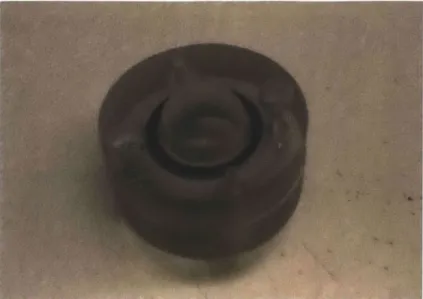
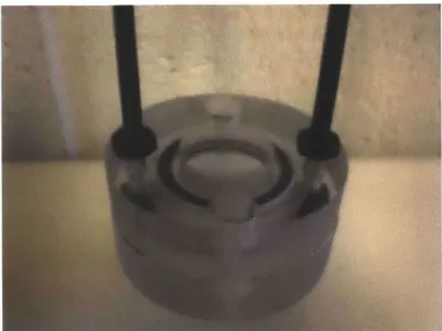
Another design modification was made at this point; the use of individual bolts made assembly difficult, as inaccessibility of the bolt head made tightening difficult (see Figure 6). Furthermore, the counterbore would need to be very deep to accommodate both bolt head and nut within the cylinder, possibly compromising the strength of the bolted joint. As a result, a continuous threaded rod would be used throughout the cylinder with nuts to attach each successive stack. As another proof of concept experiment, the existing fabricated cylinder was modified to fit the 8-32 threaded rod. It was verified that the 8-32 nylon sufficiently fastened the assembly and that the design provided a watertight o-ring seal (Figure 11).
Figure 11: Cylinder assembled with 8-32 threaded nylon rod, demonstrating successful sealing
2.2.2 Secondary Design: Incorporation of Ultrasound Probes
With the progression of the design, it was necessary to consider the incorporation of ultrasound probes. Probes would need to measure fluid motion from both the sides and bottom of the cylinder. Side probes would be placed radially, and offset at known, precise angles from the radial direction. Notches were included in the stacking disk design to accurately locate these side probes.
Probe incorporation revealed an inherent challenge in the modular cylinder design. The probes need to be as close as possible to the cylinder inner diameter for accurate readings; however, they cannot interfere with the o-ring used for sealing. As such, a set of fixtures would be used to precisely drill holes deeper into the ultrasound notches (Figure 12). The probes would fit snugly into these holes, allowing them closer access to the fluid without o-ring interference.
Notch
Drilled hole
At this point, design and protoyping focus shifted to the larger cylinder, with 4 cm inner diameter (Figure 13). As many probes as possible were incorporated into the cylinder
cross-section. Additionally, bolt holes were offset from the probe notches by 450 to maximize space
for probes.
Figure 13: Disk design to include ultrasound probe holders. 4 cm inner diameter shown
2.2.3 Modifications for Manufacturability
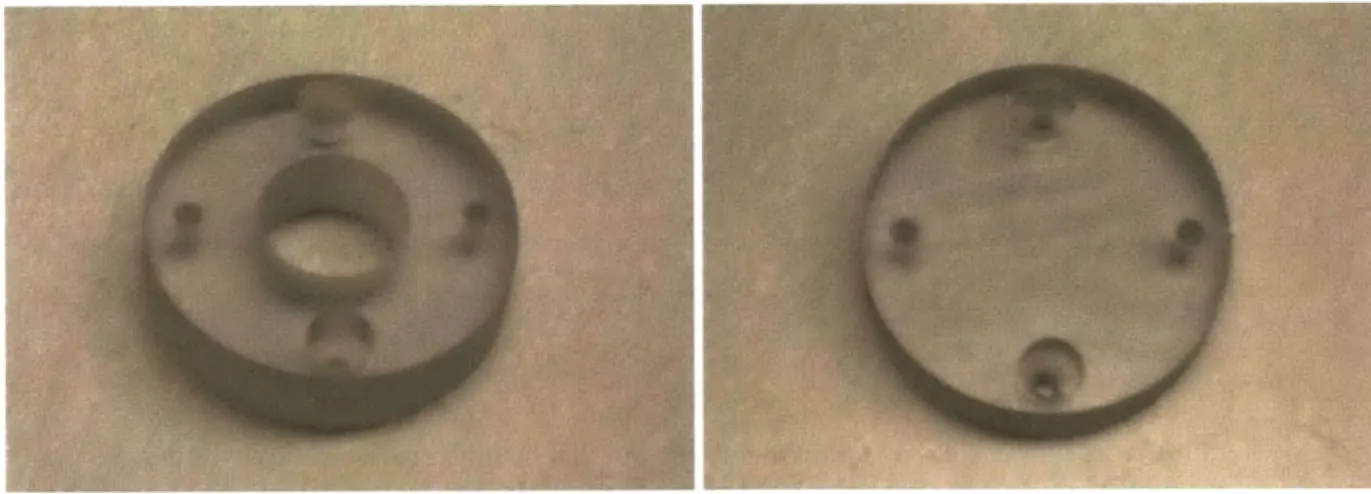
Before building the entire apparatus, a small number of disks were again manufactured to establish proof of concept. The disks were cut out of polycarbonate stock using a waterjet (Figure 14). The inner hole was undersized to eventually be cleaned on a lathe, in order to eliminate the tapered surface resulting from waterjet cutting and ensure a smooth surface finish for the inner cylinder. Other remaining operations included counterboring the bolt holes and turning the o-ring grooves on a lathe, to allow for assembly. At this point, the cylinders assembled successfully and established successful sealing (Figure 15). Finally, holes would need to be precisely drilled into the ultrasound probe grooves.
Figure 15: Assembled disks with successful sealing
Before scaling up this version of the design, however, manufacturing processes were altered for reasons of simplicity and feasibility. Rather than continuing with the waterjet cutter to produce the disks, laser cutting provided a faster cutting rate and did not require stopping the cutting process to retrieve floating parts. Furthermore, waterjet cutters are expensive to run. Therefore, switching to laser cutting drastically reduced the time and cost to make the parts. This alteration also required a change of material to acrylic, as lasers are not powerful enough to
cut polycarbonate. The new manufacturing process and material offered an additional
advantage: surface finish on the new parts was much smoother, and cutting taper was significantly reduced. These improvements eliminated the need for cleaning the inner diameter of the cylinders on a lathe, another manufacturing step that would have taken considerable time (especially because metric reamers were not available, meaning that each operation on the lathe would need to be precisely cut).
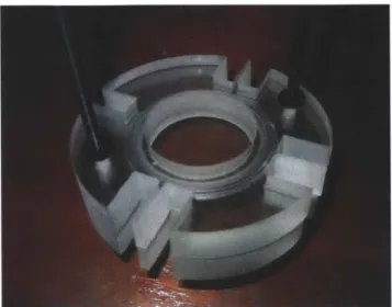
The new material, however, also required minor design changes. First, it became apparent from the first cutting attempt on the laser that thin features in the design would need to be eliminated; due to material melting during laser exposure, the thin strips between probe holder
notches either warped or broke off completely (Figure 16). These features were readily
eliminated, as they were not critical to the function of the probe holder.
Broken thin feature
In addition to the cylinder disks themselves (Figure 17), a number of fixtures were fabricated to aid in the drilling of probe holders (Figures 18-19). Fixtures were designed to eliminate the need for repeated positioning on a milling machine and allow for simple, repeatable fabrication on a drill press. A first set of fixtures, one for each of the cylinder sides, was used to hold the cylinder in place and ensure that the drilled surface was perpendicular to the drill bit. A second set of fixtures fitted onto the face being drilled, and located the holes themselves. Following this process, the located holes could be cut with an 8.2 mm standard tapered drill bit, used to fit the ultrasound probe diameter, then cut to accurate depth with a flattened 8.2 mm bit such that the ultrasound probe would come into contact with a flat surface. This flat surface is necessary to prevent unwanted refraction at oblique angles during probe operation.
Figure 17: Disk laser cut out of acrylic. Counterbores and small located holes visible
Figure 18: Fixtures used to constrain disks in correct plane, allowing for accurate drilling. Each fixture fits into one of the disk holder sides: A, B, C, or D
Figure 19: Fixtures used to locate drilled holes for probes. Each fixture fits into one of the probe holder sides, A, B, C, or D
The process of drilling the located holes, however, indicated a problem with the proposed design. Although the drilled holes were located within sufficient tolerances for the proper functioning of ultrasound experiments, they were positioned very tightly between the bottom face of the cylinder and the o-ring groove (Figures 20-21). The holes that were misaligned slightly, therefore, broke through a face of the disk and would lead to failure in cylinder sealing (Figure 22). These small misalignments occurred due to play between the fixtures and disks. In other words, drilled hole locations did not achieve the very tight tolerance required for the drilled hole to fit under the o-ring groove and within the width of the cylinder.
Figure 20: Small locating holes drilled
Figure 21: Large holes drilled
At this point, experiments with the ultrasound system and the fabricated disks indicated that the probes could read accurately through a significant thickness of acrylic material: 8 mm, between the inner diameter and the probe holder face prior to any drilling operations. This feature provided an alternative to the problematic, drilled probe holders. Therefore, a final design was achieved, whereby the drilled holes were eliminated completely, and only the existing
notches were used to hold probes. O-rings were replaced with thinner versions, of 2 mm
thickness rather than 3 to 4 mm, to reduce the distance between the probe holder face and the inner diameter. Additionally, the final design could account for a maximum of 4 probe positions per disk, as each probe would need to fit tightly into a single 8.2 mm notch.
2.3 Final Designs
Designs were completed for both the large and small cylinders, with 4 cm and 2 cm diameters, respectively. As a result of the iterative design process detailed above, the final containers include the following features:
e Stacking disks to obtain modularity and variable aspect ratio
- Two bolt holes in each disk, allowing stacking assembly with nylon threaded rods
and nuts
e Counterbores on one side of each bolt hole to accommodate nut size
e Grooves to fit o-rings between disks, achieving sealing for oil-based and water-based
fluids
- Notches to locate and secure ultrasound probes
The large inner cavity of the fluxball is cylindrical with a 15 cm diameter (see Figure 4). This inner dimension limits the maximum vessel height to be 9 disks of %" height (7 disks not including caps). The resulting cylinder aspect ratios for the design are presented in Table 2.
Table 2: Cylinder aspect ratios (height/diameter)
Number of disks Inner diameter = 4 cm Inner diameter 2 cm
(caps not included)
1 0.3175 0.635 2 0.6350 1.270 3 0.9525 1.9050 4 1.2700 2.5400 5 1.5875 3.1750 6 1.9050 3.8100 7 2.2225 4.4450
2.3.1 Large Cylinder
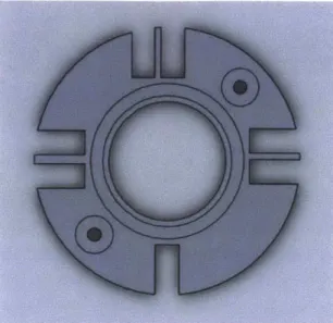
For the large cylinders (4 cm inner diameter), four types of final disks were designed and manufactured. The first is the basic disk, with four slots for probes (Figure 23 and 24). One probe faces the radial position, and three probes sit at offset angles from radial: 5, 10, and 150.
Figure 23: Large cylinder design: top view of disk, with sketch indicating probe holder geometry. Inner diameter is 4 cm; outer diameter is 8.89 cm
Figure 24: Large cylinder design: standard disk with probe holders
A second type of "blank" disk was also manufactured; this disk serves the same purpose as the basic disk, with an o-ring groove and counterbored holes to allow stacking, but it does not contain any probe slots (Figure 25). The elimination of probe holder grooves resulted in significantly decreased cutting time on the laser; therefore, since not all possible heights would
always need to be used for probe measurement on the full cylinders, a number of these simple blank disks were fabricated.
Figure 25: Large cylinder design: blank disk without probe holders
The other two types of disks made are the caps, upper and lower. The lower cap (Figure 26) features an o-ring groove to allow sealing, as well as a probe holder to measure fluid flow along the axis of the cylinder (the z-direction).
Figure 26: Large cylinder design: lower cap
The upper cap (Figure 27) does not require an o-ring, since it is the last stack on the top and will contact the o-ring on the disk below. However, the upper cap does include two through holes to allow for the filling of ferrofluid. The use of two holes, rather than one, aids in the elimination of bubbles while filling. The holes are threaded for %"-20 plastic screws, which seal the cap after fluid has been inserted.
Figure 27: Large cylinder design: upper cap
The stacks are assembled using two 8-32 threaded rods and 8-32 hexagonal nuts. A complete cylinder is pictured in Figures 28-29.
Figure 29: Large cylinder design: transparent portion displays o-ring groove, probe holder location, and counterbored holes for 8-32 rod and nuts
2.3.2 Small Cylinder
The corresponding design for the small cylinder (2 cm inner diameter) is displayed in Figures 30-36.
Figure 30: Small cylinder design: top view of disk, with sketch indicating probe holder geometry. Inner diameter is 2 cm; outer diameter is 63.5 cm
Figure 31: Small cylinder design: standard disk with probe holders
Figure 33: Small cylinder design: lower cap
Figure 35: Large cylinder design: disks stacked into cylinder
Figure 36: Small cylinder design: transparent portion displays o-ring groove, probe holder location, and holes for 8-32 rod and nuts
2.3.3 Fluxball Fixture
Finally, it was necessary to design a fixture that would secure vessels in the fluxball apparatus. Cylinders need to sit upright in the inner fluxball, such that the rotating magnetic field is in a plane perpendicular to the axis of the cylinder. It should be noted that the cylinders are positioned horizontally when loaded, but sit vertically when the fluxball is completely assembled. Using existing geometry of the fluxball as support, a simple fixture was designed to constrain the cylinder (Figure 37-38). The design can be built out of stacking slices, bolted together with a threaded rod and nuts, and fits into the fluxball without any additional constraints or hardware. For very short cylinders, which would fall through the fixture once positioned
upright and be left unconstrained in the fluxball, a simple stopper piece can be added to the end of the fixture.
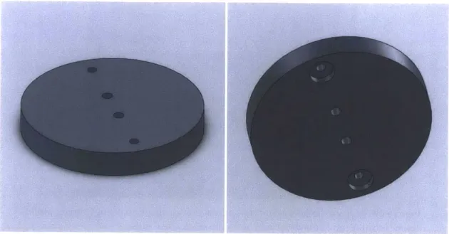
Figure 37: Fixture to contain cylinders within fluxball apparatus. Second version includes stopping piece to constrain short cylinders
Figure 38: Circular stacking pieces for fluxball fixtures; large version (left) and small version (right)
2.4 Final Manufacturing Process
2.4.1 Cylinders
Cylinders were manufactured for the large version design, with 4 cm inner diameter. In order to manufacture the four types of disks detailed above, three disk versions would need to be laser cut: one for the standard disk, one for the blank disk, and one for the caps. The standard disk also features etched letters to easily identify the four available probe angles. These laser cut disks are pictured in Figure 39. Cutting was performed on a Universal Lasers VLS6.60, at 100% power and 1% speed.
Figure 39: Disks cut from acrylic using laser. From left to right: disk with probe holder capability, blank disk without probe holder capability, and cap for top or bottom of stack
The next manufacturing step was the cutting of o-ring grooves on a lathe. As with earlier prototypes, this operation was performed on a manual lathe with a specially altered tool to allow for a face cut of the groove (Figure 40). Using a grinder, a steep relief angle was cut into the tool to keep it from rubbing on the cylinder face while making the groove. Careful precision was required, as a deep o-ring groove would result in failure of the seal, while a shallow groove would result in a significant gap between the two mated disks and disruption of the inner cylinder surface. Disks with finished o-ring grooves are pictured in Figure 41. Counterbores were then added using a drill press (Figure 42).
Figure 40: Custom tool used to make o-ring grooves on lathe; top view (top left) and side view showing relief angle (top right). Zoomed-in view (bottom) shows original profile, before custom grinding, in red
Figure 41: Top view of disks with o-rings inserted
Figure 42: Disk completed for assembly, including counterbores and o-ring groove
The top and lower caps required additional processing steps. The lower cap required a probe holder to detect flow along the axis of the cylinder (z-direction); this operation was completed using a CNC lathe in manual mode. An undersized flat endmill was used to drill the initial hole to depth with the tailstock, followed by the use of a boring tool to achieve the proper 8.2 mm diameter. This process allowed for a precisely sized hole, with the flat face required for proper ultrasound function. The finished disk is pictured in Figure 43.
Figure 43: Cap for bottom of cylinder, displaying o-ring groove and blind hole for z-direction ultrasound probe
The upper cap includes two threaded holes for filling fluid (Figure 44). drilled using a drill press, and then manually tapped to %4"-20 size.
The holes were
Figure 44: Cap for top of cylinder, with threaded holes for filling vessel with fluid and
closing with screws. Note: o-ring groove here is superfluous
2.4.2 Fluxball Fixture
Layers for the fluxball fixture were fabricated on the laser cutter, using polycarbonate of 3/16" thickness. This material and thickness were chosen to be easily cut by the laser at 100% power and 15% speed. Further, ten layers of 3/16" thickness could be assembled to fit well inside the dimensions of the fluxball with the necessary precision. (The final layered thickness
was not a critical dimension, as the orientation of the fixture in the fluxball would cause the assembly to sit squarely even if undersized.) Sheets were assembled using nylon screws, and excess melted material was removed using a file.
2.5 Results
Following fabrication, all disks were assembled to check for proper sealing. Examples of assembled cylinders, for both large aspect ratio ("tall") and small aspect ratio ("short"), are
pictured in Figures 45-48.
Figure 45: Sample assembled cylinder, tall
Figure 47: Sample assembled cylinder, short
Figure 48: Sample assembled cylinder from top, short
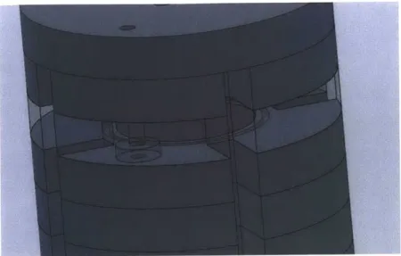
The finished fixtures constrained the cylinders as desired inside the inner fluxball. The finished fixtures are displayed in Figure 49; Figures 50-51 show an assembled cylinder fitted inside the fluxball with ultrasound probes installed.
Figure 49: Fixtures for long and short cylinders
Figure 50: Long cylinder inside inner fluxball
3. Experimental Design
Experiments were conducted at MIT's High Voltage Research Laboratory, located in Building N10. Experimental design was based on experiments previously conducted by Dr.
Shahriar Khushrushahi using the same testing apparatus and software (Figure 52); as a result,
equipment was already calibrated and verified as appropriate for ferrofluid experimentation.
Figure 52: Experimental setup
3.1 Fluid Properties
All experiments thus far were conducted with an oil-based, purchased Ferrotec© ferrofluid, EFH1. The measured speed of sound in EFH1, a required parameter for ultrasound sensing, is 1116 m/s [2]. The fluid was also mixed with particles to be detected by the ultrasound probes,
Griltex-Pi with concentration 0.008g/ml. Before each experiment, the cylinder containing
ferrofluid was mixed using a Lab-Line 3520 tabletop orbital shaker for 15 minutes at 300 RPM. 3.2 Ultrasound
The Signal Processing DOP2000 was used to perform pulsed ultrasound velocimetry on the ferrofluid being tested, allows for the measurement of bulk flow. Using the system's multiplexer mode, velocity profile measurements could be taken for up to four probes at a time. The velocimeter measures fluid velocity in the direction perpendicular to the probe face, with a positive velocity corresponding to flow away from the probe. The WDop software was used to collect and save data from the ultrasound probes. Parameter settings for the velocimeter are provided in Table 3 below.
Table 3: Velocimeter settings
Velocimeter Parameter Value
Channels 1-4 Multiplexed
PRF 100 Hz
Emitting Frequency 4MHz
Power Level High
Burst Length 8 cycles
Resolution 0.28 mm
(0.14 - 0.56 mm for z-direction)
Sensitivity Very High
Time Gain Control Slope, 31-61dB
Starting Depth 1 us
Number of Gates 200
Number of Profiles 32
Emissions per Profile 128
3.3 Fluxball
The fluxball apparatus (Figure 53) was used to generate a uniform rotating magnetic field for testing. This machine utilizes wound coils around an inner an outer sphere; a current phase difference of ±900 for the outer sphere with the respect to the inner sphere produces the desired rotating field. It should be noted that for the experiments conducted here, the inner fluxball was loaded horizontally, not vertically as pictured below. With respect to the cylinders viewed from the top, a phase difference of +90' corresponds to a counterclockwise magnetic field rotation, while -90' corresponds to clockwise field rotation.
Figure 53: Fluxball apparatus [5]
The fluxball was energized to the desired current and phase difference using a custom LabView program, pictured and described in Appendix D.
3.4 Data Collection Process
The cylinder to be tested was assembled and filled with EFH1 fluid containing GrillTex particles. An additional cylinder disk was placed on top of the upper cap while filling the vessel, to serve as a "well" and aid in the elimination of air bubbles. Once the cap was sealed, the cylinder was mixed using the orbital shaker for 15 minutes at 300 RPM. The cylinder was then placed into the inner fluxball, and probes were inserted into the desired measurement positions. Wrapping the probes with Teflon tape ensured tight fitting inside the notches. Ultrasound gel was used as a contact medium between the probes and acrylic probe holder faces.
The cylinder design allows for many combinations of possible probe positions. For the initial set of data, it was necessary to select a subset of critical probe positions to investigate the phenomenon of flow driven by the demagnetizing effect of container shape. For this reason, data was collected at three probe heights: the disk at the middle of the cylinder, and the disks located at the two ends (top and bottom). Measurements were taken at the radial position and known offset angles from radial, allowing for characterization of the bulk flow pattern. A probe was also placed in the z-direction. The maximum number of probes on the multiplexer (4) limited data acquisition, such that multiple runs were necessary to measure all probe positions. It should be noted that for very short cylinders, made of less than three disks not including the cap, less than three heights were measured.
Following probe installation, the inner flux ball was closed and loaded into the outer
fluxball. The entire apparatus was closed and secured, with all connections completed to achieve the continuous coil winding. Before the application of any current, baseline data was measured
using the WDop software. The fluxball, operating at a high resonant frequency of 95 Hz, was
then gradually energized to a IA current with +90* phase difference, and data was recorded again. This method of current application allowed fluid velocity to build up steadily. The
process was repeated to collect four sets of data for each cylinder: 1 A and 2A RMS current, at
±90* phase difference. Corresponding magnetic field strengths generated by the fluxball for these currents were 50.6 and 101.2 RMS Gauss fields, respectively [2]. The experimental process was repeated for the same cylinder, to complete data collection for all desired probe locations.
For each set of conditions, time was allowed for the system to reach steady state before recording data. Sufficient time also passed between experiments, such that the fluxball and ferrofluid cooled to approximately room temperature (25' Celsius); this allowance minimized temperature effects on the magnetic susceptibility of the ferrofluid [2]. An air hose, driven by a compressor, was also inserted into the inner flux ball to aid in the cooling process, while a thermocouple placed inside the inner ball provided verification of proper cooling.
3.5 Data Processing
The WDop software output velocity data in ASCII format, providing depth and velocity data over time. Data analysis was performed using Matlab. Samples were time-averaged for presentation of results. In addition to the pure velocity data, radial and offset probe data were combined to determine fluid velocity in the tangential direction. The offset probe geometry is detailed in Figure 54; a is the offset angle from the radial direction.
Ultra-sound probe
Figure 54: Flow measurement geometry for offset probe, from top view of cylinder. Probe is positioned at angle a with respect to the radial direction, and measures x component of velocity, v,m(x) [2]
A radial probe features the same geometrical relationship as the offset probe, except that a is equal to zero. As a result, the radial probe can be said to measure in the r-direction rather than the x-direction.
According to Figure 51 above, the azimuthal (phi-direction) fluid velocity can be derived from the following equation:
x )x 2 +(Rsina)2
v,(r) =v,.(r) - v,..(x)
Rsina Rsina
where vr(r) corresponds to the radial probe measurement, and vm(x) corresponds to the offset probe measurement. R is the inner radius of the cylindrical container, and a is the offset angle from radial [2].
Finally, the probe angle must be corrected to account for refraction as the ultrasound beam passes through the acrylic material and into the ferrofluid (Figure 55). This correction is only necessary for the offset probes, as the radial and z-direction probes are oriented perpendicularly to the inner cylinder surface. The refraction angle can be calculated as follows:
s C2sina)
where a is again the angle of offset from radial. Ci and C2 are speed of sound values in the
acrylic material and ferrofluid, respectively; the value for acrylic is listed as 2750 m/s [6]. The speed of sound for EFH 1 was measured to be 1116 m/s [2].
Refected beam a I ncident beam Medium 7 ';Medimf2 Refracted beam
Figure 55: Ultrasound beam showing original angle a, refracted angle y, and reflected angle
P
[6]4. Experimental Results
The primary cylinders investigated experimentally were those with the smallest and largest height-to-diameter aspect ratios allowed by the design: 0.3175:1 (1 disk) and 2.2225:1 (7 disks). For clarity, results in this section are presented for the stronger field strength (RMS 2A) only. "CW" and "CCW" denote clockwise and counterclockwise magnetic field rotation with respect to a top view of the cylinder.
Additionally, it is also helpful cylinder, a positive magnitude for the clockwise direction, while counterclockwise direction.
to note that for circular flow, with respect to a top view of the vm(x) measured by the 50 or 100 offset probe corresponds to a negative magnitude for vm(x) corresponds to the Baseline results, taken without the presence of any applied magnetic field, have been subtracted from the measured velocity data in order to eliminate noise present in the ultrasound transducers. For the computation of velocity in the azimuthal (phi) direction, baseline data values were also subtracted from the measured values. Complete raw data, including baseline velocity and all measured field strengths, is presented in Appendix F.
4.1 Short Cylinder
For the small aspect ratio magnitude (Figure 56).
case, flow in along the axis of the cylinder is relatively small in
Z PROBE
1 2 3 4
2 (Mm)
5 6 7 8
Figure 56: Z-direction probe velocity measurements for 1-disk cylinder
Radial direction velocity vr(x) is also small in magnitude (Figure 57). 0.4
j
0.3[
0.21
01 -0.2 -0.3 x XXX x X ** jXX ~ X X ~ XX x X XXX Xx
RMS
2ACCW
+ RMS 2A CWTRADIAL PROBE 0.3 0.2 0.1 10 -0.2 --0.3 --0.4 --15 -10 -5 0 r (mm) 5 10 15
Figure 57: Radial probe velocity measurements for 1-disk cylinder
The offset probe measurement shows that vm(x) takes on a significant value when the
magnetic field is applied (Figure 58). Clockwise field rotation creates a positive direction flow,
or away from the probe, and counterclockwise field rotation creates negative direction flow, or towards the probe; these directions provide evidence that flow is moving in the direction of the rotating magnetic field.
5 DEGREE OFFSET PROBE
0.31 0.1 0 -0.1 -0.2- >1 -0.4 - > < I ~ Wx? 01,m~<lx 04 I -15 -10 -5 0 x(mm) 5 10 15
Figure 58: Offset probe velocity measurements for 1-disk cylinder
X *x + x4 ~t~*'%, ~****~'* ~. *#4~***~.~ * .# % , * ~ ~%. 4 * ~ ~%. ~ *. * ** * -.4 -M4 x RMS 2A CCW I I I I x RMS 2A CCW 1 + RMS 2A CW
f-The radial and offset probe measurements are combined to calculate azimuthal
(phi-direction) velocity (Figure 59). Results indicate that flow is circular; azimuthal velocity
increases with distance from the cylinder center. This observation is corroborated by negligible flows detected in the z and radial directions, as presented above. The magnitude is also large compared to other measurements, with a maximum velocity of approximately 6 mm/s.
PH DIRECTION 6 -1 rXmm kx 10 j-2. -4 >c FS 2ACCW * RMS 2ACW -15 -10 -5 0 5 10 15
Figure 59: Phi direction velocity for 1-disk cylinder
For the low aspect ratio case, internal magnetic field properties are not uniform due to demagnetizing effects as described in Section 1.2. The observation of large flow, therefore, supports the theory that flow is driven by non-uniform internal magnetic field properties. The circular pattern also suggests that these demagnetizing effects promote rotational flow in the cylinder.
4.2 Tall Cylinder
For the large aspect ratio case, velocity along the axis of the cylinder shows greatest deviation from baseline at the ends of the cylinder and relatively low magnitude at the center (Figure 60). This significant z-direction flow may indicate non-circular flow in these regions.
Z PROBE (x x x x x X X 0 x x * ~ .. 4. * x
RMS 2A CCW
+ RMS2ACW < (XX *q . X x x x x><x
+*'Xxl
10 20 30 40 50 60 70 80 z (mm)Figure 60: Z-direction probe velocity measurements for 7-disk cylinder
4.2.1 Top Region
At the top vr(r), indicating
of the cylinder, the radial probe detects significant magnitude for the value of that flow is non-circular (Figure 61).
RADIAL PROBE, TOP
1 0.8 0.6 0.4 S0.2 0 -0.2 -0.4 -0.6 -0.8 -1 r (mm)
Figure 61: Radial probe velocity measurements for 7-disk cylinder, top height 0.31-
0.21-0.1
-0.2 x X X VX -0.-1 -0.4 I-0 **40* x x *x x x ) *1' * X^ VoThe offset probe measurement also indicates significant magnitude for vm(x) (Figure 62).
10 DEGREE OFFSET PROBE, TOP
-10 -5 0
x(mm)
5 10 15
Figure 62: Offset probe velocity measurements for 7-disk cylinder, top
Again, the radial and offset probe measurements are combined to calculate azimuthal (phi-direction) velocity (Figure 63). Flow magnitude is large, reaching a maximum of approximately 4 mm/s, and the non-symmetric pattern indicates that flow is non-circular.
PH DIRECTION, TOP
r (mm)
Figure 63: Phi direction velocity for 7-disk cylinder, top
0.8 -0.6
[
0.4[
-0.4 -0.6 -15 x RMS 2ACCW SRMS 2ACW I I I I4.2.2 Middle Region
At the middle of the cylinder, low values for radial direction flow and the calculated phi velocity indicate a circular flow pattern (Figure 64).
0.2 i0 7'-0.2 -0.4
--0.6
0.8
-RADIAL PROBE, MIDDLE
x RMS 2A CCW
+ RMS 2ACW
-15 -10 -5 0
r (mn)
5 10 15
Figure 64: Radial probe velocity measurements for 7-disk cylinder, middle
The offset probe probe measurement indicates larger magnitude for vm(x) (Figure 65). Clockwise field rotation creates a positive direction velocity, and counterclockwise field rotation creates negative direction velocity; therefore, flow is moving in the direction of the rotating magnetic field.
I-0.6
10 DEGREE OFFSET PROBE, MDDLE
0.6
0.4
-15 -10 -5 0
x(mm)
Figure 65: Offset probe velocity measurements for 7-disk cylinder, middle
The calculated azimuthal velocity shows approximately circular flow in the direction of the rotating magnetic field (Figure 66). Not including the noisy region at the beginning of the sample, the magnitude reaches a maximum of approximately 2 mm/s; this value is significant, but smaller than the flow velocity seen at the top of the cylinder and in the low aspect ratio case.
PH DIRECTION, MDDLE x x X xRIAs 2A CCw .I RS 2A Cw -15 -10 -5 0 r (mm)
Figure 66: Phi direction velocity for 7-disk cylinder, middle
0.2 0 -0.2
-0.4
-0.6 x RMS 2ACCW * RMS 2ACW I 5 10 15 5 10 154.2.3 Bottom Height
Velocity at the bottom height shows that radial velocity vr(r) is negligible, again indicating the presence of circular flow (Figure 67).
0.6
0.4 0.2
-0.21
RADIAL PROBE, BOTTOM
- x RM S 2A CCW
+ RMS 2ACW
-15 -10 -5 0
r(mm)
5 10 15
Figure 67: Radial probe velocity measurements for 7-disk cylinder, bottom
The offset probe measurement indicates significant magnitude for vm(x) (Figure 68). Clockwise field rotation creates a positive direction velocity, and counterclockwise field rotation creates negative direction velocity; again, flow is moving in the direction of the rotating magnetic field.
-. 61 -0.8
10 DEGREE OFFSET PROBE, BOTTOM - -xRMS 2A ccw +RMS 2A cW 0.8 0.6 0.4 -15 -10 -5 0 x(nmm) 5 10 15
Figure 68: Offset probe velocity measurements for 7-disk cylinder, bottom
The calculated azimuthal velocity shows roughly circular flow in the direction of the rotating magnetic field (Figure 66). The magnitude reaches a maximum of approximately 2 min/s, which is similar to the value at the middle of the cylinder.
PH DIRECTION, BOTTOM
r (mm)
Figure 69: Phi direction velocity for 7-disk cylinder, bottom
Taken together, these results provide insight as to fluid behavior at the three separate heights and within the cylinder as a whole. Small, circular flow at the middle of the cylinder indicates
0.2 I0 2 -0.2 -0.4 -0.61 -0.8
that flow in that region may be driven by the existence of spin diffusion or forced by flow in upper and lower regions. Velocity measurement along the axis of the cylinder provides further evidence for this hypothesis, with increased activity near the end regions and less flow at the center. Flow has larger magnitude at the top of the cylinder, which supports the theory that non-uniform magnetic field properties drive flow within the cylinder. However, the flow is not circular, which one would expect due to large circular flow observed in the small aspect ratio case. This pattern inconsistency may indicate the presence of a free surface or partial free surface, due to improper filling of the cylinder and the persistence of air bubbles. Previous research has shown that a free surface results in flow direction reversal at the top of a cylindrical container [2]. Flow at the bottom of the cylinder is roughly cylindrical, which could support the non-uniformity theory; however, the magnitude is not significantly larger than flow at the center of the cylinder.
5. Conclusions and Continuation of Work
Experiments with a small aspect ratio cylinder indicate significant rotational fluid velocity in the direction of magnetic field rotation. The large magnitude of the result supports the behavior
model predicted by the non-uniformity theory.
For the large aspect ratio case, z-direction data indicates that flow along the axis of the cylinder is larger at the top and bottom. The middle of the cylinder exhibits relatively small magnitude circular flow in the direction of magnetic field rotation. At the top of the cylinder, flow is greater in magnitude. While this evidence supports the presence of flow driven by non-uniform magnetic properties, the hypothesis is challenged by the smaller magnitude of roughly circular flow at the bottom of the cylinder. Furthermore, the non-circular pattern at the top height, indicated by significant radial velocity, suggests that a free surface may be present due to error in filling the container.
It should be noted that a relatively small data set has been collected with the apparatus thus far. Furthermore, not all experimental tests have yielded consistent results. An additional set of data for the large aspect ratio cylinder is provided in Appendix G; it is likely that this second data set differs from that presented above due to less careful adherence to the experimental methods outlined in Section 3.4. For example, less time was allowed for each experiment to reach steady state flow before data collection and for proper fluid settling and cooling to occur between experiments. In any case, the inconsistency of results reveals sensitivity of the experimentation to testing procedures and other sources of error. As a result, more measurements are necessary to verify the repeatability of results presented in this thesis.
As the cylinder design provides for many combinations of cylinder heights and probe positions, additional data should be collected with the containers to further investigate the fluid flow patterns observed in this work. The smaller version cylinder design (2 cm inner diameter) could be manufactured for experimentation, as it would provide an even larger aspect ratio than the existing container. Additional parameters may also be altered to obtain more data, such as ferrofluid type (including water-based fluid) and magnetic field strength.
Improvements and additions could also be implemented for future vessel iterations. More versions of the lower cap, with off-center z-direction probes, would provide further insight into fluid flow behavior. Currently, ultrasound probes are susceptible to being displaced if the wires
are pulled during setup; this issue was remedied by taping the wires down during installation in the fluxball, and by using probes that were accessible from one side of the vessel for each experimental run. Considering the critical nature of probe orientation, it may be worthwhile to manufacture a small piece that pushes and holds the probes into place inside their respective notches. Additionally, there is no functional necessity for the outer shape of the container to be circular, as long as the inner cylinder remains intact; as a result, the overall geometry of the containers can be easily changed to optimize probe installation during experimentation. Specifically, geometry of the stacking disks could be altered to decrease the length of the probe holder notches, as shallower notches would allow easier access to the acrylic surface.
References
1. Rosenweig, Ronald E. Ferrohydrodynamics. Mineola, NY: Dover Publications, 1997. 2. Khushrushahi, Shahriar Rohinton. "Ferrofluid Spin-up Flows From Uniform and
Non-uniform Rotating Magnetic Fields." Ph. D., Department of Electrical Engineering and Computer Science, Massachusetts Institute of Technology, 2010.
3. Khushrushahi, Shahriar and Zahn, Markus. "Ultrasound velocimetry of ferrofluid spin-up flow measurements using a spherical coil assembly to impose a uniform rotating magnetic field." Journal of Magnetism and Magnetic Materials 323 (2011) 1302-1308. 4. "UDV Transducers: Program Overview, Standard Transducers." Signal Processing S.A.
http://signal-processing.com/transducers/udvtransducersframe.htm
5. Lawler, Clinton T. "A Two-Phase Spherical Electric Machine for Generating Rotating
Uniform Magnetic Fields." M.S., Department of Electrical Engineering and Computer Science, Massachusetts Institute of Technology, 2007.
6. User's Manual, DOP2000 Model 2125/2032. Software 4.00, Revision 2. Signal Processing S.A.
Appendices
Appendix A: Mechanical Drawings, Large Cylinder Note: All drawing dimensions are in millimeters.
Lower cap:
2 x Q 4.496 THRU ALL
L__J 0 12.700 T 3.810
Basic disk, page 2: 9z 9?; 0 C C oot4
7U -
0
(n2 x 0 4.496 THRU ALL
L__J O 12.700 T 3.810
2 x 0 4.496 THRU ALL
LJ 0 12.700 T 3.810
Appendix B: Mechanical Drawings, Small Cylinder Lower cap: i
2 x 0 4.496 THRU ALL
Basic disk, page 2:
0
00 0 All, Q)-2 x 0 4.496 THRU ALL L 1 0 12.700 T 3.81C 2.066
2 x Q 4.496 THRU ALL
L 0 12.700 T 3.810
Appendix C: Mechanical Drawings, Fluxball Fixture Circular stacking piece, large: I I I I
CD
4 x 0 3.797 THRU ALL
Rectangular
stacking
piece:
J--Stopping piece:
Switch controls field's rotational direction
Individual on/off switch for each fluxball RMS current set point for fluxball
windings
Fluxball frequency
Current through fluxballs plotted in these charts
PID gains to maintain current magnitude in individual fluxballs with tuning
7 switches
Phase difference between outer fluxball and inner fluxball current PID gains to maintain current phaseZ
difference with tuning switch
Figure 5-22. Front control panel of program in NI LabVIEW 8.2 showing all the controls needed to maintain the magnitude, phase and frequency of the current in the individual fluxball windings.
Appendix E: Part List
Acrylic sheet stock was obtained from the MIT Central Machine Shop. Other parts were purchased from McMaster-Carr*; part numbers are listed.
Cylinders
* '%" thickness acrylic sheet stock
e 8-32 nylon threaded rod 0 8-32 nylon nut
* 2 mm x 24 mm Buna-N o-ring (small cylinder, 2 cm diameter) * 2 mm x 44 mm Buna-N o-ring
(large cylinder, 4 cm diameter) Fluxball Fixture
e 3/16" thickness polypropylene sheet stock
* 6-32 nylon threaded rod * 6-32 nylon nut # 98743A215 # 94812A1 14 # 9262K189 # 9262K529 # 8742K234 # 98743A210 # 94812A113
Appendix F: FuH Raw Data Set
Results in this section are displayed including baseline data and all tested magnetic field strengths. Short Cylinder Z PROBE 0.5 0.4 -0.3 -0.2 0 \ V -0.1 -0.2 -0.3 baeli RMS 1ACCW RMS 1ACW -0.4 - RMS 2A CCW RMS 2A CW -05 1 2 3 4 5 6 7 8 z (mm) RADIAL PROBE 0.5 0.4 0.3 0.2 -0.2 -0.3 baselne RMS1A CCW -0.4 RMS 2A CCW -0.5RMS 2A CW -15 -10 -5 0 5 10 15 r (mm)
5 DEGREE OFFSET PROBE x (mm) PH DIRECTION r (mm) 0.5 0.4 0.3 0.2 0.1 0 -0.1 -0.2 -0.3 -0.4 -0.5
Z PROBE 0.5 0.4 0.3 0.2 0.1 -0.1 -0.2 --0.3 -0.4 --0.5 10 20 30 40 51 z (mm)
RADIAL PROBE, TOP
0.8 0.6 0.4 --0.2 -0.4 -0.8 --0.8 --1 5 -10 -5 0 r (mm) Tall Cylinder
10 DEGREE OFFSET PROBE, TOP 1 0.8 0.6 0.4 0.2 -0.2 -0.4 -0.6 -0.8 -15 -10 -5 0 5 x (mm)
PHI DIRECTION, TOP
6 4 -2 -4 RMS1ACCW RMS 1ACW RMS 2ACCW RMS 2ACW -6 -15 -10 -5 0 5 r (mm)
RMIAL PROBE, MDDLE 1 0.8 0.6 0.4 0.2 0 -0.2 -0.4--0.6 -0.8 -15 -10 -5 0 5 r (mm)
10 DEGREE OFFSET PROBE, MDDLE 1. 0.8 -0.6 -0.4 ---. 2 ---0 3 -0.2 --0.4 --0.6 --0.8 -1 I I I -15 -10 -5 0 5 x(mm)
PHI DIRECTION, MIDDLE
r (mm)
RADIAL PROBE, BOTTOM
r (mm) 0.8 0.6 0.4 0.2 0 -0.2 -0.4 -0.6 -0.8 -1
10 DEGREE OFFSET PROBE, BOTTOM
x(mm)
PHI DIRECTION, BOTTOM