Design and Signal Processing of Finger Photo Plethysmograph Ring Sensors for Reduced Motion Artifact and Circulation Interference
by
Reginald C. Hutchinson B.S., Mathematics (1999)
Morehouse College B.M.E., Engineering (1999)
The George W. Woodruff School of Mechanical Engineering Georgia Institute of Technology
Submitted to the Department of Mechanical Engineering and the Department of Electrical Engineering and Computer Science in Partial Fulfillment of the Requirements
for the Degrees of
Master of Science in Mechanical Engineering and
Master of Science in Electrical Engineering and Computer Science at the
Massachusetts Institute of Technology May 2002 ? r
C 2002 Massachusetts Institute of Technology All rights reserved
Signature of Author
'Department of Mechanical Engineering }May 24, 2002 Certified by
Hanjhiko Harry Asada Ford Professor of Mechanical Engineering
Thesis Supervisor
Accepted by
Ain A. Sonn Chairman, Dep rme$Committea Graduate Students
De menf Mechanipal'Engineering Accepted by_________
Y-kmur %-. 3mn
R Chairman, Committee on Graduate Students
MASSACHUSETTS S iIUTE Department of Electrical Engineering and Computer Science OF TECHNOLOGY
Design and Signal Processing of Finger Photo Plethysmograph Ring Sensors for Reduced Motion Artifact and Circulation Interference
by
Reginald C. Hutchinson
Submitted to the Department of Mechanical Engineering and the Department of Electrical Engineering and Computer Science on May 20, 2002 in Partial Fulfillment of
the Requirements for the Degrees of Master of Science in Mechanical Engineering and Master of Science in Electrical Engineering and Computer Science
ABSTRACT
This work centers on creating a new design for a photo plethysmograph ring sensors to address the problems of previous ring sensors. Two major issues are addressed: to improve the signal-to-noise ratio and lack of motion detection. A new design for photo plethysmographic devices is presented to increase the amplification of arterial volumetric pulsations. The unit provides a mechanism capable of pressurizing the finger base at localized point, thus circulation is not obstructed. An experiment study compares the new design with a cuff system. Results show that the new design does not obstruct the blood, while the cuff does. In addition, the new design will decrease corruption of the
signal due to saturation effects from ambient light and small motion perturbation.
Motion detection was also presented in this work. Based on size and power constraints, an autocorrelation method in addition to a 2nd photodetector (motion detector) were
decided upon. The motion detector is more susceptible to motion, thus providing a noise reference. An algorithm using the autocorrelation method determines if motion is present based on the noise reference.
Thesis Supervisor: H. Harry Asada, Ph.D.
Ford Professor of Mechanical Engineering, Director, d'Arbeloff Laboratory for Information Systems and Technology
ACKNOWLEDGEMENTS
During my time at the Massachusetts Institute of Technology, I have encountered many trials and tribulations. Without the love and support from family and friends, these
last few years would have been too overwhelming.
First of all, I would like to thank God for giving me not only the strength and endurance to fulfill my obligations, but for proving me with the mindset to undertake endure each obstacle and challenge in my life. Providing me with a continuous cast of friends, allowed my spirits never to be crushed.
I would like to thank my advisor, Professor Asada for his guidance, support and patience. These last years under his tutelage have strengthened my skills and provided
me with additional knowledge which will last a lifetime.
I would like to thank my father. Besides being a role model everyday of my life, his continuous wisdom and unconditional love makes me grow closer each day to become half the man he is. I would like to acknowledge my mother, for her goodwill and nature provide me with a strong fundamental basis to withstand and endure challenges in my life. Inheriting her strong desires, and ability to burn the midnight oil which has been critical during this phase. Treasure, my twin sister, deserves recognition for always motivating me and inspiring me to reach my potential. She is definitely one of the most important people in my life who has been there for me and requires nothing in return. Thank you for always been so understanding and loving. You have been always been a great friend.
Then there is always Nishan, a brother to me since day one. No matter if he is in California or London, no matter if it is 4 p.m. or 4 a.m., he is always available for me to talk his head off. Thanks for being there. Crandall and Shane, two other friends that have never left my side. I am fortunate to have them in my life. Back then I never knew what I had when I had it. They have shown me what true friends are.
There are some organizations, which in need to acknowledge that have been a place support and a stress outlet. These organizations are: The Black Graduate Students Association, Graduate Student Council, BSU, and Greater Boston Morehouse College Alumni Association. In addition I would like to thank the Graduate Student Office who have provided counseling and guidance all throughout my stay. Dean Colbert, Dean Staton and Dean Charles have always gone above and beyond there duties to assist those in need. And to Mamma Leslie deserves thanks for taking time out of her busy life to help a young man out.
I would like to recognize ASADA GROUP for proving the lab place to be a good home. Outings, lab lunch and volleyball definitely make coming to work a little better. Also, they constantly show support and unselfishness by always willing to help someone
else no matter their workload.
And lastly to Mike and Byron. Friends whom I came in with that have definitely shown that they will always be around to the end. My experience at MIT will always have them in memory.
And I have to special thanks to R.C. and the General. You have definitely helped me sustain my sanity.
CONTENTS
1. Introdu ction ... 9
1.1 Introduction ... 9
1.2 B ackground ... 10
1.3 O utline of Thesis... 12
2. Review of the Ring Sensor... 13
2.1 Description of the Ring Sensor... 13
2.2 Theory of Photo Plethysmography... 14
2.3 Review of the Dynamics of the Arterial Wall ... 19
2.4 Issues with the Present Ring Sensor... 21
3. Design of New Ring Sensor... 26
3.1 New Components of the Ring Sensor... 26
3.2 On Board Signal Processing... 30
3 .3 R esu lts... 3 1 4. E ffects of Pressure... 35
4 .1 Introduction ... 35
4.2 Effects of Uniform Pressure ... 38
4.3 Effects of a Localized Pressure... 44
4.4 Comparison of Methods... 49
4.5 Observation of Occlusion at the Arm... 50
5. M otion D etection ... 53
5.1 Introduction ... 53
5.2 A ccelerom eter... 56
5.3 Maximum Likelihood Method... 56
5.4 Autocorrelation Method... 58
5.5 M otion D etector... 59
5.6.3 Autocorrelation Method... 67
5.6.4 M otion D etector... 77
6. Ring System Monitoring... 80
6.1 Introduction ... 80
6.2 Additional Sensor Components... 81
6.3 Im plem entation ... 83
6.3.1 Cadmium Sulfide Photocell... 83
6.3.2 N TC Therm istors... 85
6.4 Ring Monitoring System... 87
7. Conclusion and Recommendations... 90
Appendix A: Software Code... 93
m otiondetect.m ... 93
rundetect.m ... 95
p lotauto .m ... 96
H istP D F .m ... 97
run_ p d f m ... 98
Appendix B: Drawings and Images... 100
Drawing of New Components... 100
Pressurizer and Equipment... 101
Appendix C: Filter Characteristics... 104
LIST OF FIGURES Figure 2.1 Figure 2.2 Figure 2.3 Figure 2.4 Figure 2.5 Figure 2.6 Figure 2.7 Figure 2.8 Figure 2.9 Figure 3.1 Figure 3.2 Figure 3.3 Figure 3.4 Figure 3.5 Figure 4.1 Figure 4.2a Figure 4.2b Figure 4.3 Figure 4.4 Figure 4.5 Figure 4.6 Figure 4.7 Figure 4.8 Figure 4.9 Figure 4.10 Figure 4.11 Figure 4.12 Figure 4.13 Figure 4.14 Figure 4.15
Conceptual design of the ring sensor... 14
Optical model of the finger... 15
Absorption spectrum... 16
Components of Plethysmograph ... . ... 17
Pulse oximeter calibration curve... 18
Change of arterial wall radius with transmural pressure ... 20
Pressure-diameter relationship of human digital artery... 20
Modeled sinusoidal output signal... 24
Model of the saturation effects due to ambient light... 25
Components of pressurizer... 27
Components on Sensor Band... 27
Performance of new design under motion... 31
Experimental effects on increasing ambient light intensity... 33
Pressurizer's response of ambient light... 33
C alibration of Pressure... 38
Finger cuff apparatus... 39
Finger cuff apparatus (schematic) ... 39
Finger cuff set-up... 40
Experimental Setup of finger cuff... 41
Pulse Amplification due to finger cuff... 41
Comparison of pressure and amplification at the fingertip using finger cuff. 42 Effects of occlusion by application of finger cuff... 43
Set-up for localized force measurements... 44
Application of set-up for a localized force measurements... 45
Observing the effects of force exerted locally at the finger base... 45
Prototype of the new ring sensor design... 46
Applying a pressure locally to photo plethysmograph waveform... 47
Observing the effects of local pressure at the fingertip and the finger base... 48
A rm cuff set-up ... 50
Figure Figure 5.2 5.3 Figure 5.4 Figure 5.5 Figure 5.6 Figure 5.7 Figure 5.8 Figure 5.9 Figure 5.10 Figure 5.11 Figure 5.12 Figure 5.13 Figure 5.14 Figure 5.15 Figure 5.16 Figure 5.17 Figure 5.18 Figure 5.19 Figure 6.1 Figure 6.2 Figure 6.3 Figure 6.4 Figure 6.5 Figure 6.6 Figure 6.7 Figure 6.8 Figure 6.9 Figure 6.10 Figure 7.1 Figure 7.2
Effects of motion inside and outside bandwidth of interest... Mean pressure of essential vessels in the body...
53 59
Absorption Spectrum... 60
ACH 04-08-05 accelerometer and test board... 61
Circuit diagram of the accelerometer board... 62
Performance of the accelerometer... 63
Analysis of motion artifact from PPG sensor... 64
Environmental Effects... 65
Probability density function of pulse and motion signal... 66
Flow chart of motion detection algorithm... 67
Plot of a non-motion signal and corresponding autocorrelation... 69
Plot of a motion signal and corresponding autocorrelation... 69
Examining the effects of random motion... 70
Finger bent less than 1 Hz... 73
Finger bent at 1 H z... 74
Finger bent greater than 1 Hz... 75
Finger tapped on a flat surface... 76
Motion detector and photodetector signal... 77
Data validity assurance schematic... 80
A dditional sensors... 81
CDS photocell applied to ring sensor board... 83
Circuit diagram of CDS photocell and filter... 83
Experimental results of CDS sensor... 84
Thermistor located on the band... 85
Calibration of the thermistor... 85
Hand immersed in 18 0C H20... ... ... ... 86
Ring Monitoring System... 87
Ring Monitoring System Deluxe... 88
Adaptive Noise Canceller... 91
LIST
OF TABLESTable 2.1 Extinction Coefficients for Hemoglobin... 18
Table 5.1 Motion Detection of a Random Motion... 71
Table 5.2 Motion Detection of a Finger Bent Less Than 1 Hz... 73
Table 5.3 Motion Detection of a Finger Bent at 1 Hz... 74
Table 5.4 Motion Detection of a Finger Bent Greater Than 1 Hz... 75
Table 5.5 Motion Detection of a Finger Tapped on a Flat Surface... 76
Table 5.6 PPG D etector... 79
CHAPTER 1
INTRODUCTION
1.1 Introduction
If new medical devices had increased functionality without compromising their accuracy, they may become commonplace in hospitals and other medical realms. Among the most common health monitoring instruments used in the medical arena are pulse oximeters. Pulse oximeters are medical devices used to monitor aspects of personal health, such as pulse rate and blood oxygen saturation level. Though devices such as ambulatory EKG monitoring devices have added the functionality of mobile monitoring, they place a load upon the individual. For long-term monitoring, this load can cause significant discomfort for the user. Other devices such as the FinaPres, noninvasive continuous finger blood pressure monitor, based on the vascular unloading technique, can monitor the patient, but have the potential to impede circulation throughout the finger
[29].
The introduction of the photo plethysmographic device, termed the "new ring sensor" is a cost-effective complement that enables subjects to be monitored despite movement and without supervision by a medical professional. In addition, the use of this assistive monitoring equipment will aid medical facilities by improving a diagnostic tool that can help determine the status of the patient [10]. As such, this new device will make more efficient use of scarce health care workers. The equipment has been shown to meet various constraints including power consumption, weight, comfort, and accuracy.
Though this ring sensor has been shown to compare with other renowned devices such as EKG and other current FDA approved devices [19], several deficiencies persist. Also, the ring sensor has the potential to increase in its functionality thus becoming more durable.
The goal of this thesis is to develop a new ring sensor design to improve the signal-to-noise ratio my means of inducing a localized pressure at a point on the finger base without interfering with the blood circulation. A motion detection system will also be introduced to improve the performance of the ring sensor. Though these features will be provided, constraints and the performance of the original ring sensor will be met. In addition, the new design will decrease the corruption of the signal due to saturation effects from ambient light and small disturbances due to motion. Though, this framework is applicable to the ring sensor, it can be modified slightly such that other photo plethysmographic sensors can benefit from these findings.
1.2 Background
During the last century, many people experimented with photo plethysmography. This field was a highly active area of research in the development of non-invasive blood monitoring devices to aid the patient and provide a user-friendly apparatus to the medical professional using the equipment. From research involving ear photo plethysmographic devices in the 1940s [5], to Yamasitha's first analog photo plethysmograph sensor [19],
to the present day pulse oximeters, technology has shown great advancement. In addition, temperature and pressure effects have been observed with photo
plethysmographic devices. It is observed that if heat were produced into the system, better circulation would result, providing a more reliable signal. Safety issues and regulations are considered to ensure that the heat is not uncomfortable to a patient. Pressure effects on a photo plethysmograph sensor have been investigated by use of various finger cuffs [21]. Important parameters, such as the blood pressure, were obtained using these devices. Others researchers observed the tradeoffs of using
increased pressure to provide and accurate measurement. They accessed the state of how much pressure can be applied before serious complications can result [9].
The area of motion artifact has been a nuisance in producing and accessing the status of a patient. A motion artifact disrupts the signal to extent where it cannot be recovered. Because of the distorted waveform, it is difficult to capture certain physical characteristics. If motion can be detected, the sensor unit can take some action to ensure the data is reliable. Current pulse oximeters vary with this feature. Among those devices that contain this aspect, have an indicator to alert the user or medial professional. Though some devices indicate motion others attempt to eliminate motion. Though many people have committed extensive research to address the issue of motion artifact rejection such as Barreto and Vicente, it is still a highly thought of area of research since motion artifact still plagues many photo plethysmographic sensors [1]-[3]. If motion can be reduced or eliminated, prominent features can be extracted out of the measurement.
1.3 Outline of Thesis
This thesis focuses on how the new ring sensor design can solve key issues with the previous ring sensor and other photo plethysmographic devices. In addition, this new unit will improve the signal-to-noise ratio and establish a motion detection system. Chapter 2 begins this discussion by proving the reader previous information regarding the ring sensor, the theory in which it operates, and present issues with the previous ring sensor design and other photo plethysmographic devices. The next chapter, Chapter 3, goes on to provide a discussion on the new ring sensor design, operation of the unit, description of its components and their functionality, and resolution of issues as a result of the design. Chapter 4 focuses on the added functionality of signal-to-noise enhancement, while not impeding circulation to other essential parts of the finger. To show this improvement a comparison of localized point pressure and a uniform surface pressure are presented. Chapter 5 discusses the key issues with motion artifact. It investigates 4 key methods for motion detection: accelerometer, maximum likelihood method, autocorrelation technique, and an additional photodetector. It will evaluate the pros and cons of each method and based on the performance and abilities to meet current constraints, will decided the best method. Chapter 6 will describe the ring sensor monitoring system. Three additional sensors will be utilized for behavior and environmental monitoring. Chapter 7 will conclude this thesis with conclusions from this project and a list of recommendations for future improvement.
CHAPTER 2
REVIEW OF THE RING SENSOR
2.1 DESCRIPTION OF THE RING SENSOR
A brief description of the present ring sensor is reviewed in order to provide familiarity with the unit. The ring sensor is a miniature, low power continuous monitoring device. Encompassing the idea of pulse oximetry, it can provide important information about the wearer. The ring sensor uses two light-emitted diodes (LED) (660 nm and 940 nm) and a photodiode. If the sensor is wireless, then additional components are needed: a CPU, RF transmitter, and a battery unit. For purposes related to this research, concentration is placed on a wired ring sensor, such that the additional noise from the wireless network was not captured by the system. Whether wireless or wired, the ring sensor has the ability to modulate the two LEDs. The result, the signal-processing unit can monitor the arterial blood volume at the finger base. This information is transmitted to the host computer where further computations can yield the pulse rate and the arterial oxygen saturation level. In addition to calculating these parameters, the host computer serves as a data storage, and a means where the pulse waveform and the desired attributes can be displayed.
Battery
RF Transmitter CPU
Photo Diode
LEDs
Figure 2.1 Conceptual diagram of the ring sensor [12]
The ring sensor uses both the theory of photo plethysmography and the knowledge of the dynamic wall in its design. The following sections will discuss these two ideas.
2.2 Theory of Photo Plethysmography
Photo plethysmography (PPG) is a method of measuring the cardiovascular pulse waveforms by optical means. Pulse oximetery uses photo plethysmography to measure the arterial oxygen saturation by a non-invasive spectrophotometric method [13]. Pulse oximeters are products in medical field which uses these theories to evaluate the pulse rate and the blood oxygen saturation level of an individual. Their ability to measure these parameters non-invasively makes them preferred by the public. Because of real-time monitoring capabilities and accuracy, they are commonplace in the hospitals and continuously used by medical professionals for initial diagnosis. Though many pulse
oximeters can differ in geometry, location on the body, and performance under different external factors, they all use the theory of photo plethysmography to obtain the pertinent information. 2k2 Artry Artery 2 Artery 1 r2=(X2,Y9) Tissue Banana Shaped Light Paths
Light Source Light Detector
r,=(O,0) rd(lO)
Figure 2.2 Optical model of the finger and optical elements. Blood vessels have different optical properties from the tissue. [121
By using three components, two LEDs and a photodiode, the amount of blood volume can be measured. The photons from the LEDs pass through the skin. Although the photons illuminate in all directions, it is known that the average light path travels in a banana shape through a portion of the tissue and then back to the photodetector [19].
Although, some scattered light escapes through the finger, it will be assumed that the light emitted is absorbed solely by the anatomy of the finger and the photodetector. In light of this fact, Beer- Lambert's law can be applied to find the properties of amount of light absorbed.
,where I is the original intensity of the light, c(X) is the extinction coefficient of
absorbitivity at a specific wavelength k, c is the concentration of the substance absorbing the light, and d is the optical path length. Certain have substances have shown to have a distinct spectrum when shined at different wavelengths [5]. Figure 2.2 shows the absorption spectrum for methaemoglobin, oxyhaemoglobin, deoyhaemoglobin, and carboxyhaemoglobin.
Absorption Spectrum
A da pted 01i-01m:
hUp ://'ww Ith.a de aidedu aena skbrazioxygn ind ks/rame'1 mr
Figure 2.3 Absorption Spectrum
Focusing on the absorption spectrum for oxyhaemoglobin (HbO2) and
Table 2.1: Extinction Coefficients for Hemoglobin [4] Wavelength [nm] Extinction coefficient [L mmol -lcm~1]
Hb HbO2
660 0.81 0.08
940 0.18 0.29
The DC component of the signal is primarily affected by the absorption in the intensity of light source, ambient light, sensitivity of the detector, tissue bed, bone, venous blood, capillary blood, and non-pulsatile arterial blood [27]. The AC component captures the pulsating arterial blood (see Figure 2.4).
AC
L.h...*
.. ... .
oc'
pulsatile atterial blood absorption
non-p4satie arterial blood absorption venous and capilaty blood absorption
tissue absorption
Fig. 4, Illustration of the absorption signal at a single wavelength. The pulsatile AC signal is small compared to the non-pulsatile signal: however, it is a distinguishing feature of arterial
blood absorption. (Adapted, with
permission, from Ohmeda Pulse Oximeter Model 3700 Service
Manual, 1986:22.)
TIME
If the DC and AC component are known at two different wavelengths of light, then R can be computed, where R is given by the following equation:
R
AC660 DC660AC9401DC940
(2.2) [24]
It has been proven that this ratio is empirically related to oxygen saturation (Figure 2.5).
0I 100 90 80 70 60 50 40 30 20 10 0,4 0.6 O. 1 1,2 1,4 1.6 1.8 2 2.2 2.4 2,6 2,8 3 3.2 3.4 R
Figure 2.5 Pulse oximeter calibration curve. [24]
Therefore, possessing two LED wavelengths, one at 660 nm and one at 940 nm, the blood oxygen saturation level can be computed. In order to find the pulse rate, one of the two waveforms generated by the two different LEDs can be examined. With knowledge of
2.3 Review of the Dynamics of the Arterial Wall
The previous ring sensor uses an elastic band to secure the optical components to the skin. It is held in place by applying a sufficient amount of a uniformed external pressure around the finger, but avoids causing discomfort to the wearer. The dynamics of the arterial wall will be analyzed to determine the sufficient amount of pressure. It is known that as the blood travels throughout the body through a series of capillaries, veins, and arteries. Each vessel has certain pressure but differs depending on the location of the body [8]. The arm has a blood pressure or 120 mmHg, while the finger has a blood pressure of 100 mmHg. These pressures can vary depending on the orientation of the feature. If the hand is raised or lowered, the internal blood pressure will be affected. This pressure, called the internal pressure, provides information regarding the health status of a patient. Knowledge of the internal blood pressure and the external blood pressure can yield the transmural blood pressure, given by the difference between the internal pressure Pi and external pressure P0 [19]. Knowing the transmural pressure, the radius of the artery can be computed. Therefore, if there is a small amount of external pressure applied to the finger, it produces a relatively small change in the radius of the artery, as shown in Figure 2.6. If the external pressure is further increased such that the transmural pressure approaches zero, the radius is the unstressed radius, which is shown by equation 4.3. In addition, a small change in the transmural pressure around zero, yields a large change in radius of the artery. This is due to the non-linear behavior of the arterial wall compliance, i.e. the slope of the radius-trnasmural pressure curve in Figure
2.6. Note that the compliance becomes maximized near the zero tranmural pressure. Assuming that the length of the artery is fixed, the volume of the blood in the artery is proportional to the square of the radius. Thus, as a result of the radius increasing, the
Ir2
A P, Figure 2.6 Change of arterial transmural pressure (Pt) [191 - 101 -'.0 0 40 60 20 p I mKg QP." Pi * Arterial Wall P I
wall radius (Rr) with
I
PAN
Figure 2.7 Pressure-diameter relationship of human digital artery. The pressure in the x-axis is transmural pressure (Pi - P), and the y-axis is external diameter. The external diameter is about 0.8 mm at when it is completely collapsed, implying that the wall thickness at the collapse is about 0.4 mm. [19]
blood volume increases, which causes the volumetric arterial pulsations to increase. If the external pressure is further increased, the transmural pressure decreases, which causes the artery to occlude. If an external force is further applied, complete occlusion develops.
--. Mwo )!
P Pt = P - P1P - 0
P blood pressure inside artery (4.1) Po pressure outside of artery
r[x] = roI ro P(x) (4.2)
1 Eh _
Thus, sensor band applies enough pressure such that the occlusion does not develop in the artery, but supplies enough pressure to improve the signal.
2.4 ISSUES WITH THE PRESENT RING SENSOR
Although the previous design of the ring sensor has been proven to have comparable results to that of other pulse oximeters devices, there are some issues that remain. These issues include:
* Pinching effects * Management of Wires * Necrosis of the finger " Motion Artifact * Ambient Light
These drawbacks are addressed in this section. Based on the following, a new ring sensor will be designed to remedy these issues.
The previous ring sensor uses the notion of the inner and outer ring [19]. The outer ring consists of two sections: one that fits around the top of the finger base, and the
other section affix underneath the finger base. When these sections are brought together to secure onto the finger, they have the potential to possess a fraction of the skin in between its sections. When clamped together, a section of skin between the two sections is caught and squeezed causing the finger to feel a pinching effect. This pinch causes discomfort and pain for a short period of time.
The ring sensor possesses five 36 gage flexible wires used to connect the sensor band to the signal-processing unit. Though these wires are small, they are not robust when there is a small amount of interference. Also, if the sensor band is separated from the ring sensor unit beyond a certain distance, these wires detach themselves from the unit or from the sensor band. When this results, the LEDs do not get power nor the information from the photodetector is received. In either case, the output from the device is inaccurate. A method needs to be developed to reduce the occurrence of this problem.
The elastic sensor band provides a uniform pressure onto the skin to occlude the vein, but not interfere with the arterial pulsations. This was designed because the venous
contribution is more susceptible to motion artifact. Therefore, occluding the vein results in a reduction of motion artifact sensed by the ring sensor. Though this uniform pressure can improve the signal, it also has the potential to cause discomfort for some users. If the finger is too large, occlusion will develop thus leading to necrosis if the band is applied for a long period of time. Necrosis is the pathologic death of one or more cells due to externally imposed forces [23]. Though the elastic band can be substituted for a different size band, the pressure exerted onto the finger cannot be adjusted. Thus,
In addition to the above problems, the previous ring sensor is continuously subjected to noise, but motion artifact is by far the main contributor [12]. Despite different means to reduce it, motion artifact still remains a constant issue for inventors, medical professionals, and patients. This motion causes the relative displacement between the skin and the photodetector to vary, as well as rotational effects placed on the ring sensor. It also affects the tissue mechanics of the body. A continuous change in the position of the finger has an effect of continuously changing the amount of light absorption from the tissue. Therefore, the amount of light contacted by the photodetector is affected. These factors make it difficult to obtain an estimate of the blood volume by photo plethysmography. The waveform is distorted resulting in inaccurate measured parameters. In addition, the analyst must locate all regions of motion to ensure that these regions be discarded when evaluating a patient. To provide a device for reducing motion artifact without causing ischemia, detecting motion, and notifying the analyst where the regions of motions are located will be beneficial.
The ring sensor utilizes photo plethysmography to obtain the pulse of the patient. Using this method requires use of a controlled light source and a photodiode. Though the band around the figure is elastic to ensure a tight pressure fit, the geometric shape of the board of the photodiode prohibits a fit free of gaps. Thus, an excessive amount of light due to an external light source, such as sunlight, can be detected by the photodiode. The increase in light causes the current of the photodiode to increase. If the current goes beyond a threshold, the first stage amplifier is saturated. This saturated pulse will not reveal the find the maximum amplitude of the signal nor the local extrema of the signal,
which can will lead us not being able to find heart rate variability, pulse, etc. To observe these saturations effects, this in depth, a model has been constructed.
The model is given by:
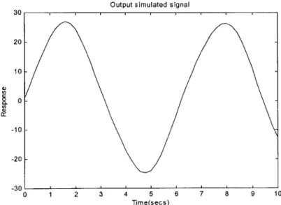
d = D sin(codt + do x = bA sin(co t) + d y = k sat -a Equation (6.1) Equation (6.2) Equation (6.3)
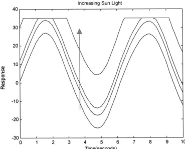
,where d, is the sunlight intensity, od is the room light freq, D is the room light intensity, co is the frequency of the pulse, A is the amplitude of the pulse, b is the LED intensity, a is the photodiode range, and k is the photodiode gain. Figure 2.8 is an example of the simulated model, assuming there are no ambient light effects interfering with the signal. Figure 2.9 shows the effects of increasing the ambient light. When this parameter is increased, the output is saturated at the crest.
30 20 10 0 CL 0 -10 -20
Output simulated signal
0 1 2 3 4 5 6 7 8 Time(secs)
9 10 -30
Increasing Sun Light 40 30 -20 10 0 9A ~0- -10- -20--30 0 1 2 3 4 5 6 7 8 9 10 Time(seconds)
Figure 2.9 Model of the saturation effects due to ambient light
Note: this model assumes that the signal is a sinusoidal signal. This is sufficient since the signal received from a photo plethysmographic device is similar to a sinusoidal signal.
This section provided some insight to the issues, which plague the ring sensor. A new ring sensor was. In subsequent chapters, a new ring design will be presented to
address majority of these issues. If issues are not resolved by hardware, additional signal processing techniques will be utilized to solve the remainder of these problems.
CHAPTER 3
DESIGN OF NEW RING SENSOR 3.1 New Components of the Ring Sensor
This new design consists of a housing unit, which will aid photo plethysmographic ring sensors. This device has been designed to remedy the issues discussed in the previous chapter. In addition, there were several design criterions established. First, the device must be lightweight such that the user suffers no long-term discomfort. Secondly, the device must be relatively easy to apply and disengage from the user. This process must have a relatively quick learning response and must have a change over time no longer than 2 seconds. Third, the housing unit must protect the optical sensors from outside interference other than ambient light. These interferences are due to a direct force applied to the sensory unit. Lastly, the device must have the capability to adjust the amount of pressure applied to the skin, in addition to providing a mechanism to ensure contact between the photodetector and the finger.
NEW RING UNIT- "Pressurizer"
Sensor
band
Base
.. ....
Figure 3.1 Components of Pressurizer
Components on Sensor Band
Photo detector A for main PPG signal Photo detector B
for noise reference
LED's: Red/IR
Figure 3.2 Components on Sensor Band
To address these various issues, the new ring sensor design termed, "The Pressurizer" arose. The Pressurizer consist of 5 major parts:
The Cover
The lightweight cover is made of a material made from cast acrylic. This unit has an inner diameter of 0.78 inch, but widens to 1.03 in diameter in order to interact with the base unit. The main function of the cover is to protect the sensors from outside elements. Also, it reduces the influence of external forces. Being decoupled from the sensor band, a direct force on the surroundings of the sensors will not affect the output of the signal. In addition, the cover unit serves in limiting saturation stemming from ambient light.
Base Unit
The base unit is made of the same cast acrylic material. With a tight tolerance of 0.01 of an inch diameter smaller than the inner diameter of the cover, this unit can connect with the cover to provide a secure fit by means of friction. The base units main function is to limit the elastic sensor band to only rotational motion. This component also manages small wires stemming from the signal-processing unit to various sensors located on the sensor unit. Moreover, this component aids in shielding the ambient light, which the cover unit could not handle.
Sensor Band
A tight elastic band used in the previous design of the ring sensor is replaced by an adjustable band. Because this band is made adjustable, it adds the feature of being flexible for fingers of various sizes. Having the sensor loose around the finger base
lowers the occurrence of necrosis. Like the previous sensor band, it possesses the photodetector and the two LED, which provides the photo plethysmographic response.
Adjuster
Because the sensor band is loose, the optical components are not secured around the finger base. The adjuster component provides contact between the photodetector and the skin. The adjuster places pressure directly on the finger base. In addition, the adjuster can tune the pressure applied such that the transmural pressure approaches zero to provide an improved signal. A setscrew is used for this application such that it is hidden from the view for aesthetic purposes.
Pressure Band
The pressure band is a rubber material whose main function is to alleviate direct stress on the photodetector. Without the pressure band, applying pressure directly on the
photodetector can induce a sufficient amount of stress. If the stress is too intense,
localized stress fractures can develop in the photodetector. This incidence will cause the photodetector to not operate properly. A pressure band relieves this induced stress. Also, using a pressure band applies pressure not only to the photodetector, but a small area
around the photodetector. Therefore, the adjuster can be around a general area of the photodetector and still function properly.
Motion Detector
A second photo plethysmographic sensor is added to the sensor band to provide a means detecting motion. The sensor is located 90 degrees away from the location of the initial photodetector. By using the information of the provided by the 660 nm LED, venous
contribution can be measured. Because the vein is more susceptive to motion artifact, then this component will be able to detect motion. Since the band has been modified such that the vein is not occluded and the location of the sensor prohibits local occlusion, then a reliable detection system can be contrived.
3.2 On Board Signal-Processing
Previously, the ring sensor possessed a series of filters to reduce noise and recover the original signal. Though the ring sensor is capable of accomplishing this task, when transferred to the computer, noise can also result. This is especially true in a wireless network. In order to provide the original signal, additional processing was done on the signal.
Using a 4th order Buttersworth Filter with a cut off frequency of 10 Hz, in to remove high frequency noise which might have appeared when taking the signal from the analog to digital converter, it is ensured that the signal is filtered. To ensure that drift or other factors causing the DC value to fluctuate, a high-pass 2nd order Buttersworth Filter.
This additional filter will eliminate the DC contribution, thus stabilizing the signal. This high pass filter is needed when using the detection method. Though pulsatile waveforms are evident, low frequencies cause them to be detected by a motion detection algorithm thus producing false alarms. Implementing this high-pass filter diminishes the
3.3 Results
Using this new design alleviated the pinching effect with the current sensor unit. The new design is familiar to the user because it slides onto the finger similar to a finger ring. If the finger changes in diameter over time, two issues result: insecure attachment of the cover and base unit and discomfort. To alleviate this concern, the wearer has the option of resizing the unit or exchanging the size of the unit. This process is familiar to those accustomed to finger rings and only happens over a significant duration in time.
Grouping all wires together with a heat shrink wires enables the five wires to be condense into one. Allowing the wires to be routed through the base unit allows a relief on stress onto the system. These wires are lead into to a flex connector, which is attached to the signal-processing board. If the flex connector is interfered with by a disturbance, it is durable enough not to break connection with the signal-processing unit or the detectors themselves.
Implementing an adjustable band remedies the potential issues of necrosis. If the finger varies in size or discomfort is felt, the band can be adjusted to accommodate the user. Since there is relatively no pressure exerted onto the skin, ischemia will be avoided. Using the adjuster to pressurize a small area of the finger base, the signal can improve the quality of the signal with out impeding the blood flow. This will be the center of discussion in chapter 4.
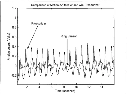
Comparison of Motion Artifact w/ and w/o Pressurizer
Figure 3.3 Performance of new design under motion
Because the band is loose, a small disturbance can cause the displacement between the skin and the sensor to vary. Using the adjuster to ensure that the photodetector is secure to the skin, a small disturbance causes no displacement between the detector and the skin. Therefore, the analog output is not disturbed and thus a reliable measurement can be made. In figure 3.3, a hand is moved back and forth at a frequency less than 1 Hz. The band in both the Pressurizer and the ring sensor were loose to avoid ischemia. When analyzing the graph, the Pressurizer performs better the ring sensor, thus reducing motion influence. Motion detection will be discussed in chapter 5.
1.2 Pressurizer 0.8 -i 0.6 - Ring Sensor :3 - 0.4 0 C:1 0.2 -0.2 2 4 6 8 10 12 14 Time (seconds) -..
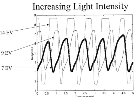
Increasing Light Intensity
B 14 EV 7 9 EV 5 'a 4 7 EV 2 1 0.5 1 2 2.5 3 3.5 4 4.5 5 Time(seconds)Figure 3.4 Experimental effects on increasing ambient light intensity
Comparing New Design Under Exposer to High Ambient Light
Pressurizer No Pressurizer
0.5 1 1.5 2 2.5 3 3.5 4 4.5 5
Time (seconds)
Figure 3.5 Pressurizer's response of ambient light (intensity of 12 EV) ci) 0~ 0) 0 (a3 C 10 5 A 0 0
Ambient light has the ability to saturate the operational amplifiers in the signal-processing unit. Figure 3.4 shows the effects of ambient light on photo plethysmographic devices when increasing the ambient light. As the intensity of light increases, saturation becomes more evident. This experimental data agrees with the model developed in chapter 2. Although techniques such as using a logarithmic amplifier or diodes to avoid saturation, another solution can be found by hardware solution. As stated in previous sections, the cover and the base unit of the Pressurizer shield ambient light from the sensors. Figure 3.5 shows that the Pressurizer does improve the sensor quality.
In addition to reducing the issues presented, various constraints such as size, weight and power consumption where checked to see if they were comparable to the previous ring design. The weight of the outer ring was compared to the weight of the cover and base of the new prototype ring sensor. Only these components were compared since the other components remain unchanged or were negligible compared to the housing unit. The outer ring from the original ring sensor weighed 6.81 grams. The Pressurizer's cover and base unit weighed 9.05 grams. This difference in weight equated to the weight of a dime. Therefore, the unit has met weight constraints. The design did not change the signal-processing unit nor added any additional power. Therefore, the original constraints of the ring sensor were met.
The upcoming chapters will focus on two key issues: motion detection and the improvement of the signal while avoiding the possibility of necrosis.
CHAPTER 4
EFFECTS OF PRESSURE 4.1 INTRODUCTION
This section focuses on how to improve the ring sensor by increasing the signal-to-noise ratio (SNR), without reducing circulation interference. In the processing unit of the ring sensor, the signal passes through a series of gains to amplify the signal. The end result consists of a pulse waveform with relatively low amplitude. Considering the magnitude is on the order of microvolts, it will be advantageous to increase the signal in a manner such that the SNR will be improved.
As stated in the background section, the SNR can be improved by exploiting the non-linear behavior of the arterial wall compliance (see Chapter 2). Therefore, applying an external force such that the transmural pressure will approach zero the pulsations will increase in magnitude. Thus, the SNR can be improved.
Low pulse amplitude
Some patients have low pulse amplitudes making the pulse detection difficult on current blood monitoring devices. When patients are exposed to environmental changes, such as temperature, the amplitude of the waveform is affected. When the ambient temperature falls, the body begins to have a reduction in heat. Though the body tries to accommodate this heat loss by shivering (an attempt to warm the body by the involuntary
contraction of skeletal muscles), the hypothalamus responds by generating a cutaneous vasoconstriction. The hypothalamus is the part of the brain that lies below the thalamus, forming the major portion of the ventral region of the diencephalon and functioning to regulate bodily temperature, certain metabolic processes, and other autonomic activities. During this vasoconstriction stage, restriction of blood flow is caused when there is a decrease in arterial pressure. When this results, the barorecepetors in the body decreases in firing, thus causing the sympathetic discharge to increase in firing. This results in vasoconstriction [11]. Since the body attempts to preserve blood for the legs, heart, and brain, the extremities are the first to feel the affects of vasoconstriction due to temperature. In addition, 90% of the functionality of the finger is used for thermoregulation [26]. Thus in cold environments, the finger is very susceptible to temperature. The new ring design has the ability to apply local pressure to ensure the contact between the skin and the photodetector. Applying further external pressure will increase the pulse waveform amplitude. Therefore, the new ring sensor will improve the SNR.
Circulation Interference
The heart pumps blood continuously, circulating oxygen and nutrients throughout the body. When using a traditional cuff or any device that applies a uniform surface pressure onto the finger or the arm, it constricts the blood vessel, thus limiting or impeding the amount of blood supplied to the areas. These actions result in a lack of nutrients and oxygen to these areas causing ischemia. Though these actions are feasible
constriction persists for long period of time, necrosis will result. Thus, the wearer cannot be exposed to these devices that use these measurements long-term. For an anemic patient, cutting off the blood supply will cause serious injury, including death.
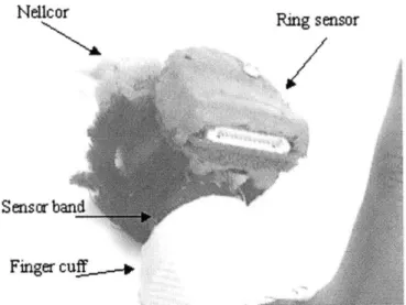
In addition to improving the SNR, the new ring sensor design will show circulation is not affected throughout the finger. To observe these characteristics, two different methods are presented: uniform pressure and localized pressure. To observe the improvements in SNR, the pulse waveform was observed by the ring sensor at the finger base. If there was a significant increase in amplitude, then the SNR was improved. An additional device, a FDA-approved photo plethysmograph sensor produced by
Nellcor was applied at the fingertip. This device was used to measure amount of
circulation interference. To observe the effects of interference, various types of pressure were applied to the individual. If the fingertip showed no effect regardless of the effects at the finger base, then there was circulation interference.
To observe the occurrence of circulation interference, a uniform pressure by means of a finger cuff was applied to the base of the finger. The pressure was increased until occlusion resulted. It will be shown that these methods improve the SNR, but potentially constrict blood flow. To observe the effects of localized pressure, the new ring sensor design was applied. The pressure was increased until the amplitude reduced to a certain point. Complete occlusion never resulted. Thus, it will be shown that this method increased SNR while not restricting blood flow throughout the finger.
4.2 Effects of Uniform Pressure
Calibration
To improve the signal-to-noise ratio, a uniform pressure can be applied to the surface of the skin. In this section, the base of the finger was pressurized.
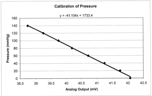
Calibration of Pressure 160 - y = -41.104x + 1733.4 E a) 0) 0 114U 120 100 80 60 40 20 0 38.5 39 39.5 40 40.5 41 Analog Output (mV) 41.5 42 42.5
Figure 4.1 Calibration of pressure
Using a blood pressure transducer the blood pressure was converted from a pressure to an analog voltage. The PowerLab 410 interface captured this voltage. The blood pressure was increased from 0 mmHg to 140 mmHg in intervals of 20 mmHg. The data
was recorded at every interval. Figure 4.1 shows linear relationship between the analog output of the blood pressure transducer and the blood pressure. Therefore, the transducer was calibrated.
Set-up
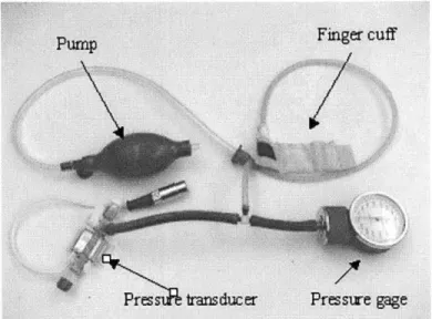
Figure 4.2a Finger cuff apparatus
Outer sleeve Plastic insulation Inflatable balloon
Velcro Air tube
fastener
Heat-shrink tubing
Figure 4.3 Finger cuff set-up
To further investigate the effects of uniform pressure along the finger base, a finger cuff was constructed using cloth, balloon, shrink wire, thread and a needle (Figure 4.2). Using this apparatus in addition to a pressure gage, pressure transducer, and a pressure controller, pulse amplification and blood circulation were examined. The
Pulse amplification
Nellcor
Senscr Finger cuf,
Figure 4.4 Experimental setup of finger cuff
Amplification of Waveform due to Fingercuff
I I I
10 20 30 40 50 60 70 00 90
Time (seconds)
Figure 4.5 Pulse amplification due to finger cuff
The ring sensor was applied to the finger base. The finger cuff was placed between the ring sensor band and the knuckle (see Figure 4.4). To increase the amplitude
Ring sensor 1.2 1 in 0 CL 0 tM CU C 0.8 0.6 0.4 0.2 0 -0.2 -0.4 -0.6
I
I
of pulsation, a finger cuff was applied to the finger. Using only the sensor band and signal processing unit, the photo plethysmograph waveform response was generated. This is shown in Figure 4.5.
,I
Jr
\
. 4 +.
Figure 4.6 Comparison of pressure and amplification at the fingertip using finger cuff
CD 1.6 01 O.E -0.' -0.
Effects of Pressure Using a Finger cuff
Finger bas
Fin 4 tip Occlusion
-A
0 40 60 8 10 20 140 160 18 200
iesec nds
Figre 4.7. Eh...foclso yaplcto f igrcf
To measure the amount of interference, a Nellcor sensor was placed at the fingertip. When pressure was exerted onto the finger base, there was a point where arterial pulsations ceased at both the finger base and the fingertip. Thus, the vein and the artery were occluded. This provided a lack of nutrients to the finger. This is shown in Figure 4.6 and Figure 4.7. Figure 4.7 examines the relationship between pressure and the volumetric pulsation until occlusion. As the pressure is increased, occlusion resulted. As the pressure is lessened slowly, circulation resumed to the fingertip. When analyzing the Figure 4.8, the initial diagnostic might seem that the increasing pressure had no affect on the fingertip, thus showing there was no interference when using a cuff. This was due to the fact that the finger consists of a network of veins and arteries. When the blood was
restricted locally, the body reacted by pumping enough blood such that a sufficient amount of blood was supplied to the fingertip. Since the finger base was the location where the pressure was applied, the ring sensor was affected. At a specific pressure, the pressure was far to great to be compensated by the body and in turn affected the fingertip. As the pressure increases, the blood vessel became further condensed, thus restricting blood to all essential areas of the finger. Again, when this pressure was exerted for a short period of time first, discomfort was felt on the finger. A tingling feeling developed on the finger since there was no blood supplied. This feeling diminished when the pressure was lessened.
4.3 EFFECTS OF A LOCALIZED PRESSURE
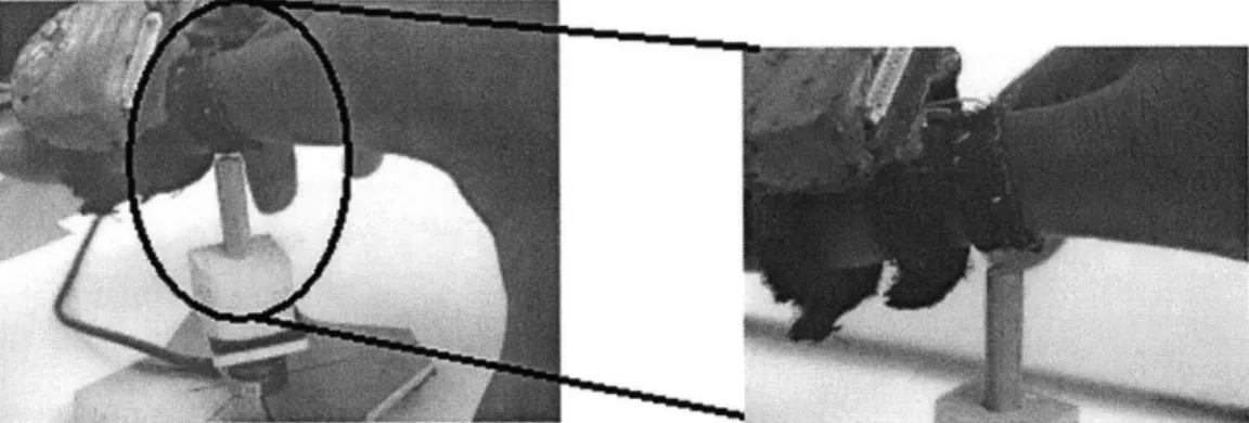
Figure 4.9 Application of set-up for a localized force measurements
Observing Effects of Force
J, .
|I
-0.021I
r
jiri~
r~~fqj~lI
0 20 40 60 80
Time (seconds)
Figure 4.10 Observing the effects of force
I
1-20
100 120 140
exerted locally at the finger base
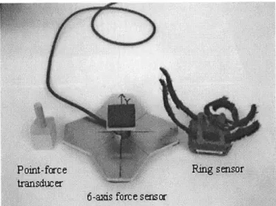
A force-point transducer, ring sensor, and a six-axis force sensor were used to observe the behavior of the photo plethysmographic response due to changes in localized force. Figure 4.8 shows these components. The force was found by pushing the finger
0.04 0.02 0 C-D <0 10 0 -0 -10
downward direction onto the force-point transducer. The transducer had a circular contact area, which had a diameter of 0.25 inches. The transducer was placed on top of the six-axis force sensor. This process is shown in Figure 4.9. The applied force on the finger base has a reactionary force at the force sensor. This enabled the measurement of the applied force. As the force increases, the photo plethysmograph amplitude increases, until it reaches a maximum as shown in Figure 4.10. This maximum point is the systolic pressure. As the force is further applied, the amplitude begins to decrease. Force and the photo plethysmographic waveform were taken simultaneously. To improve the signal-to-noise ratio, an alternative method using the new ring sensor design was investigated.
Rin sensor Pressuizer Nellcor
Sensor band (not seen)
Increasing Pressure Locally 03 0.2 0.1 0 0
4.12 r
Pressure Transition
bands
20 40 60 80 100 120 140 160
Time (seconds)
Figure 4.12 Applying a pressure locally to photo plethysmograph waveform
Pulse amplification
The new ring sensor was used to observe its effects on local pressure. Although pressure is applied only at a localized point, it is expected that the volumetric arterial pulsations increase in amplitude. Having a localized pressure also ensures contact between the elastic band and the skin as mentioned in chapter 3. The Pressurizer was adjusted to ensure contact, as well as to apply to small amounts of pressure on the tissue. Figure 4.11 shows the photo plethysmographic signals measured at three different pressures. As the pressure is increased, the waveform amplitude increases. The
transition bands are regions where the pressure was increased. Therefore, the signal-to-noise ratio is increased.
Reduced Circulation Interference
Increasing Pressure at a Localized Point
2.5 2 Finger 1 Fingertip 0 -0.5 20 40 60 80 100 120 140 160 180 200 220 Time (seconds)
Figure 4.13 Observing the effects of local pressure at the fingertip and the finger base
To measure the interference effects when using the localized pressure enhancer, the ring sensor was applied at the base while the Nellcor was located at the fingertip. Placing the Pressurizer at the finger base, local pressure was applied, thus causing the waveform at the finger base to be influenced. Figure 4.13 shows the fingertip was unaffected although sufficient amounts of pressure were applied to the base of the finger.
Since only a small section of the finger base was exposed to this force, only one of two digital arteries was affected. Knowing the fact that the finger consists of a network of
locally. Blood flow is unimpeded along the second digital artery. Thus, nutrients and oxygen were supplied to the fingertip showing no signs of circulation interference
4.4 Comparison of Methods
The difference between the Pressurizer and traditional methods is the fact that the cuff is restricting all blood flow into the finger. When comparing the results from the pressurizing the finger at a local point or along the uniform surface, it is clearly seen that both methods amplified the waveform. Further increasing the pressure will yield the
localize method to increase then decrease in volume, without impeding the blood flow to the fingertip. When increasing the pressure with a cuff, the amplitude will also increase then decrease. At a certain point the artery will be occluded thus proving no blood flow to the finger. This is due to the fact that the there is a network of veins and arteries in the finger. When pressurizing the finger locally, one digital artery is occluded, but there are other pathways which the blood can travel to reach essential areas of the finger. When using a cuff to pressurize the finger, no matter the number of different pathways the blood can travel, all pathways are blocked. Thus, it is shown that the new design gives
the ring sensor an improvement on SNR without impeding blood flow. Likewise, it gives the ring sensor the added feature of adjusting external pressure, which increases the transmural pressure.
4.5 Observation of Occlusion at the Arm
Though it has been shown that localized pressure does not occlude blood flow, occlusion of the finger can result in other ways. For instance, if the arm is rested on object, gravity might apply enough pressure such that occlusion of the artery may occur. The blood flow is lessened creating a tingling feeling or numbness. During this process oxygen perfusion is disrupted causing tissues, muscles, and other essential anatomical elements to fail to receive nutrients. Because occlusion of the arm leads results in occlusion of the finger, it would be beneficial to have a device, which validates the signal, provide the location of occlusion, and alert the medical professional during occlusion. In this section, the behavior of arm occlusion will be observed in order to develop a method of to detect arm occlusion.
Arm cuff
Pump
Pressure transducer
Pressure gage
Effects of Pressure on the Fingertip (using an Arm cuff) Occlusion 50 100 300 200 100
v
0 100 150 E E Time (seconds)Figure 4.15 Effects of pressure at the fingertip using an arm cuff
Effect of Pressure Using an Arm Cuff
Occlusion Finger base
Fingerti
50 100 150 200 250
Time (seconds)
Figure 4.16 Effects of occlusion by application of an arm cuff
1.5 1 0 0.!5 2 1.5 k >1 0 0 - . -0.5 I
To observe the effects of the effects of arm occlusion, a traditional blood pressure cuff was applied to the arm of a health 26 year old. This uniform external pressure was steadily increased to observe the characteristics of the finger base and the fingertip. The waveform showed no significant effect until the pressure exceeded a threshold value. At this value, the cuff began to restrict blood flow along the arm and the finger. The
amplitude of the volumetric pulsation of the artery was reduced as a result of this restriction. Further increasing the pressure, pulsations cease around 145 mmHg. This value marked where complete occlusion of the blood artery results. During occlusion, no blood was propagated throughout the finger, which resulted in a loss of oxygen and other nutrients to the finger. Figure 4.15 shows the relation of the photo plethysmographic response of the sensor measure at the fingertip and the pressure. Figure 4.16 shows how
circulation was impeded at the finger base and the fingertip. When comparing these results to those of the finger cuff, it can be seen that the arm cuff occluded with a faster time constant that the finger cuff. Knowing the relative amplitude of the arterial volumetric pulsations at different time instances, a decision can be made on whether
occlusion is developing at the finger base or the arm. More experimental results need to be performed to verify this result.
CHAPTER
5
MOTION DETECTION
5.1 INTRODUCTION
Motion (Noise Produced in Two Regions)
* Noise Outside Band
* Signal can be recovered by
conventional filters
* Noise Inside Band
* Noise can be reduced but not
completely removed
Figure 5.1 Motion influence on signal [25]
Motion Inside and Outside
Bandwidth of Interest
4Steady input
(Outside band)
j:
;
AMA vA~ jAA4 P' i'\ \
(It
AM ~ ~~T\
4-\f
*
'~ V
4Random input
(In and outside band)
i
11
11A
\V
AA rd4M, ."Po TV Al 13AA
T- (--0