HAL Id: hal-02518073
https://hal.archives-ouvertes.fr/hal-02518073
Submitted on 24 Mar 2020
HAL is a multi-disciplinary open access
archive for the deposit and dissemination of
sci-entific research documents, whether they are
pub-lished or not. The documents may come from
teaching and research institutions in France or
abroad, or from public or private research centers.
L’archive ouverte pluridisciplinaire HAL, est
destinée au dépôt et à la diffusion de documents
scientifiques de niveau recherche, publiés ou non,
émanant des établissements d’enseignement et de
recherche français ou étrangers, des laboratoires
publics ou privés.
Enhanced fluorescence cell imaging with metal-coated
slides
Eric Le Moal, Emmanuel Fort, Sandrine Lévêque-Fort, Anne Janin, Hideyuki
Murata, Fabrice Cordelières
To cite this version:
Eric Le Moal, Emmanuel Fort, Sandrine Lévêque-Fort, Anne Janin, Hideyuki Murata, et al.. Enhanced
fluorescence cell imaging with metal-coated slides. European Conference on Biomedical Optics, Jun
2007, Munich, Germany. pp.663007, �10.1117/12.728545�. �hal-02518073�
Enhanced fluorescence cell imaging with metal-coated slides
Eric Le Moal
a,b, Emmanuel Fort
a, Sandrine L´evˆeque-Fort
b,
Anne Janin
c, Hideyuki Murata
cand Fabrice P. Cordeli`eres
da
Laboratoire Mat´eriaux et Ph´enom`enes Quantiques, UMR 7162 CNRS/ Universit´e Paris 7, and
Laboratoire de Physique du Solide, ESPCI, 10 rue Vauquelin, 75231 Paris Cedex 05, France;
b
Laboratoire de Photophysique Mol´eculaire, UPR 3361 CNRS, 91405 Orsay Cedex, France;
cLaboratoire de Pathologie, UMR 728 INSERM/Universit´e Paris 7, Hˆopital Saint Louis,
1 avenue Claude Vellefaux, 75010 Paris, France;
d
Institut Curie – Section de recherche / CNRS UMR 146, Plateforme d’Imagerie Cellulaire,
Bˆatiment 112, Centre universitaire, 91405 Orsay Cedex, France.
ABSTRACT
The last decade has witnessed momentous advances in fluorescence microscopy.1 The introduction of novel fluorescent markers,2–4 together with the development of original microscopy techniques,5–7 made it possible to study biomolecular interactions in living cells and to examine the structure and function of living tissues. The emergence of these innovative techniques had a remarkable impact on all the life sciences. However, many biological and medical applications involve the detection of minute quantities of biomolecules, and are limited by the signal weakness in common observation conditions. Here, we show that silver and gold-coated microscope slides can be used as mirror substrates to efficiently improve detection sensitivity when fluorescence microscopy is applied to micrometer-thick biological samples. We report a fourfold enhancement of the fluorescence signal and a noticeable strengthening of the image contrast, when mirror substrates are used with standard air micro-scope objectives. We demonstrate that metal-coated substrates provide the means to get sensitivity-enhanced fluorescence detection with dry optics, while keeping a wide field observation and a large depth of field. This is a crucial advantage for automated and high-throughput applications to cell and tissue diagnostic analysis. Keywords: Mirror substrate, fluorescence microscopy, tissue imaging, cytogenetic analysis, medical diagnosis, fluorescence enhancement.
1. INTRODUCTION
In cell biology, different scales of observation provide complementary parts of information: one may need to both have a view of the global architecture of a biological tissue and access more subtle details of cell inner structure. Whereas a low magnification yields a wide observation field, one may be limited by the meager amount of collected light, low-magnification microscope objectives usually being of low numerical aperture. In that case, it might be hard to obtain reliable information from biological samples tagged with low concentrations of fluorophores.
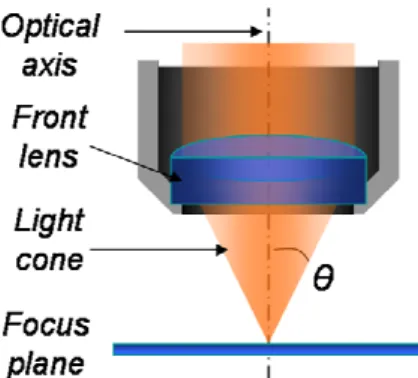
The numerical aperture (N A) of a microscope objective is defined by the light cone standing between the focus and the front lens of the objective. N A depends on the refractive index n of the imaging medium between the objective front lens and the specimen cover glass, and the angle θ which is one-half the angular aperture value (see Eq. (1)). The refractive index ranges from 1.00 for air to 1.51 for specialized immersion oils, which value is almost identical to that of the glass used for slides and coverslips.
N A = n sin θ (1)
Further author information: (Send correspondence to S. L.-F.)
E. L. M.: E-mail: [email protected]; E. F.: E-mail: [email protected]; S. L.-F.: E-mail: [email protected]
Figure 1. Schema of the light cone standing between the front lens of a microscope objective and its focus plane.
Oil-immersion microscope objectives thus provides a much higher collection efficiency than air objectives. However, oil-immersion objectives are usually available with magnification larger than 40. This category of ob-jectives thus well suits cell inner-structure imaging but does not permit visualizing the tissue structure into which cells integrate. When analyzing a tissue section, one will need to alternate between low and high-magnification objectives to link the pieces of information that are collected from the examination of cell inner-structure and tissue architecture. Proceeding in that way, while scanning the whole sample area, comes out to be a tedious and time-wasting operation because of the presence of immersion oil, and may be a serious handicap for clinical applications. Finally, high-NA microscope objectives do not suit routine applications when their use is dictated by the necessity for increasing the collection efficiency, with no need for improving the image lateral resolution. Another crucial parameter, when fluorescence microscopy is applied to biological sample analysis, is the depth of field, which is also referred to as the axial resolution or axial resolving power of the objective. In a simplified approach of microscope optics, one can assimilated the depth of field with the sample layer that provides information in the resulting image. In fact, it rather corresponds to the range of depth within which a specimen is in acceptable focus. Strictly speaking, a point object precisely positioned in the focus plane of the objective does not produce a point image, owing to the light diffraction laws which limit spatial resolution of optical instruments, but a pattern of concentric rings (the Airy-pattern). Theoretically, the width of the central peak of this pattern (the Airy-disk) roughly equals the wavelength of light. As the point object is moved away from the focal plan, the produced image gets larger. However, when the Airy-disk is sufficiently small, it is indistinguishable from a point, and appears to be in focus; it is rendered as acceptably sharp. As a result, the depth of field is the distance in front of and beyond the subject that appears to be in focus.
d =λ √ n2− N A2 N A2 + n e M N A (2)
The depth of field strongly depends on the objective numerical aperture N A, as seen in Eq. (2) where λ is the wavelength of light.8 Since the acceptable sharpness of the image produced from a point object is influenced by viewing conditions and the amount by which the image is enlarged, the depth of field also depends on the microscope objective magnification M and the detection device resolution e. Increasing the objective numerical aperture or magnification results in a decrease of the depth of field.9 For instance, the depth of field of an oil immersion objective with M = 100 and N A = 1.4 (d ≈ 0.6 µm) is typically eight to tenfold shorter than that of an air objective with M = 20 and N A = 0.4 (d ≈ 5 µm).
The mean thickness of a biological sample is usually much larger than the depth of field of oil immersion objectives. In traditional histological techniques, for instance, tissue samples are cut in a microtome at thicknesses varying from 2 to 25 µm thick. Moreover, a typical cell size is 10 µm (the size of prokaryotic and eukaryotic cells respectively ranges from 1 to 10 µm and from 10 to 100 µm). Consequently, one will constantly have to move the focal plane between the object bottom and top planes to probe the whole layer of a micrometer-thick sample. This is a major drawback for large-scale applications like medical diagnosis, and it also substantially slows down automation for high-throughput screening.10, 11 These biomedical applications involve automated optic devices and sample substrates designed for highly parallel processing, like tissue microarrays,12and become widespread in
clinical and biological research laboratories. Consequently, there is an urgent demand for all technologies aiming to overcome the limits of low-magnification air microscope objectives, in order for biologists and clinicians to achieve all the required measurements using a single objective. Here we show that the use of mirror slides may be one of those technologies.
2. EXPERIMENTAL METHODS
2.1 Substrate Preparation
The substrates were prepared under ultrahigh-vacuum conditions (UHV) on conventional coverslips or microscope slides. Prior to any deposition step, the blank slides were cleaned in Milli-Q purified water, rinsed and sonicated 5 min in a bath of absolute ethanol (with the aim of removing the residual micro-fine pieces of glass from the surface), and dried by means of a nitrogen flow. Subsequently, a silver or gold deposition was performed by thermal evaporation (see UHV chamber in Fig. 2a). Metal was heated in a crucible to the point that it evaporates into the vacuum, depositing a coating on the surface of the glass much like hot breath will steam a cold window. The temperature and timing for this procedure were controlled very precisely to achieve exactly the right thickness of metal. This method of coating creates very uniform and highly reflective surfaces. Following a method which is in widespread use throughout the mirror industry, we deposited a very small amount of chromium (2-nm-thick in nominal thickness) on the substrate surface before growing the metal film, so as to increase the metal film flatness and to ensure its adherence to the substrate.
Figure 2. Inside view of the UHV chamber where glass slides are prepared (a). Red arrows point out a holder for solid targets (for pulsed laser deposition), a set of Knudsen cells (for thermal evaporation) and a rotating arm for holding a glass slide and controlling its temperature. A schematic sketch (b) shows how mirror slides are designed and how they are meant to be used for fluorescence imaging (epi-illumination configuration).
Metal films were covered with a thin transparent layer of an amorphous oxide (e.g., alumina obtained by pulsed laser deposition) or a polymer (e.g., teflon thermally evaporated). The presence of this overlayer has many purposes. First, it endows the mirror slide with physicochemical properties similar to those of standard microscope glass slides (for alumina coating) or polymer substrates (for teflon coating), which is a crucial point for all applications involving surface functionalization. Second, it prevents the metal film from being mechanically damaged (e.g., by the strips of a sharp-ended pair of tweezers) or chemically attacked (e.g., due to oxidation of silver). The compatibility of mirror slides with biological applications is at stake in the properties of this overlayer, because biological samples for fluorescence microscopy are usually prepared on-slide. We verified that mirror slides withstand temperature, salinity and acidity, at the different steps of the biochemical protocols involved in the presented applications.
As illustrated by Fig. 2b, mirror slides are meant to be used in epi-illumination configuration for fluorescence microscopy. However, standard bright-field imaging of the stained tissues, in optical transmission microscopy, remains possible on mirror slides exhibiting nonzero optical transmission. Using Fresnel theory and the permit-tivity data of gold as measured by Johnson et al,13we calculated the transmission coefficient T of a 70-nm-thick gold layer, inserted between two quasi-infinite layers of refractive indices n = 1.33 (the biological sample) and
n = 1.51 (the glass slide), for a light beam impinging the surface in normal incidence. We found T = 0.29 at λ = 530 nm (nAu= 0.56 + 2.2i) and T = 0.16 at λ = 590 nm (nAu = 0.27 + 3.0i). From a similar calculation,
2.2 Biological Sample Preparation
2.2.1 Dog Kidney Cells
The immunofluorescence technique aims at tagging antigens and antibodies with fluorescent molecules. It com-monly employs two sets of antibodies, a primary antibody being used against the antigen of interest and sub-sequently recognized by a secondary dye-coupled antibody. For this study, MDCK∗ cells stably expressing
eGFP-α-tubulin (gift from Dr. J. P. Dompierre) were grown as monolayers on the appropriate substrate for 48 h before fixation. Cells were lysed for 2 min in 0.5% Triton X-100 and fixed in 3% paraformaldehyde in PHEM buffer as described by Coquelle et al.14 Cells were washed three times for 5 min in PBS and further permeabilized for 25 min in 0.1% Triton X-100 in PBS. Fixative was reduced by 50 mM NH4Cl in PBS for 10 min, washed three times for 5 min in PBS, blocked in PBS/BSA 0.1% and labeled with a human polyclonal anti-GMAP-21015and Mitotracker Red CMXRos (Molecular Probes, Carlsbad, CA) for 1 h at 37◦C. After washing in PBS/BSA, the
cells were incubated with secondary antibodies for 45 min (goat antihuman Alexa 633, Molecular Probes). The cells were postfixed in formaldehyde 4% in PBS for 16 min and treated by 50 mM NH4Cl in PBS for 10 min. When indicated, the DNA was stained with DAPI (Sigma, St. Louis, MO) for 5 min. Coverslips were mounted using PBS/glycerol 1:1 containing 100 mg/ml of DABCO antifading (Sigma-Aldrich, St. Louis, MO).
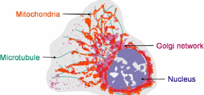
Figure 3. Captioned sketch of a dog kidney cell, showing the main elements of its inner structure.
2.2.2 Tissue Sections
Fluorescence in situ hybridization (FISH) is performed to identify the X or Y-chromosome together with im-munologic staining to characterize cell types on the same tissue section. FISH is a cytogenetic technique which can be used to detect and localize the presence or absence of specific DNA sequences on chromosomes. It uses fluorescent probes which bind only to those parts of the chromosome with which they show a high degree of sequence similarity. FISH probes are nucleic acids, tagged with fluorescent molecules. Applying FISH to a tissue section can provide very precise information on the spatial localization of the studied nucleic acids.
A tissue sample from a biopsy was formalin-fixed and paraffin-embedded, before being cut in a microtome at the thickness of 5 µm. A tissue section was prepared on a standard microscope slide, the half of which was gold-coated, following these steps:
(i) acid pretreatment: 0.2-M HCl for 15 min; (ii) heat treatment: 2× SSC at 80◦C for 15 min;
(iii) enzymatic treatment: digestion, proteinase K (100 g/mL) in TEN buffer at 37◦C for 15 min;
(iv) denaturation at 90◦C for 20 min on heating plate;
(v) hybridization at 42◦C for 16 h in moist chamber.
FISH technique involved the use of CEP X SpectrumOrange / Y SpectrumGreen DNA probe kit (Abbott Molecular, Des Plaines, IL) for sexual chromosome tagging (see fluorescence characteristics of DNA probes in
∗BSA: bovine serum albumin; DAB: 3,3-diaminobenzidine tetrahydrochloride; DABCO:
1,4-diazabicyclo-(2,2,2)-octane; DAPI: 4’,6-diamidino-2-phenylindole; eGFP: enhanced green fluorescent protein; GMAP: Golgi-microtubule-associated protein; MDCK: Madine-Darby canine kidney; PBS: phosphate-buffered saline; PHEM: piperazine-N,N’-bis(2-ethanesulfonic acid) (PIPES) / 4-(2-hydroxyethyl)-1-piperazineethanesulfonic acid (HEPES) /ethylene glycol tetraacetic acid (EGTA) / magnesium; TEN: tris(hydroxymethyl)amino methane (Tris) / ethylenediaminetetraacetic acid (EDTA) / NaCl; SSC: standard saline citrate.
Tab. 2, Sec. A). For immunohistochemistry, we used mouse antihuman CD34 antibody (endothelial cell and hematopoietic progenitor cell marker), and Peroxidase/DAB.
2.3 Fluorescence Microscopy
Images of fixed cells were collected using an imaging system described elsewhere.16, 17 Briefly, the setup is made of a Leica DM RXA microscope (Leica Microsystems, Wetzlar, Germany), equipped with a 100× PlanAPO 1.4-NA oil immersion objective positioned by a PIFOC piezoelectric translator (Physik Instrumente, Karlsruhe, Germany). Two air objective lenses (40× 0.55-NA and 20× 0.4-NA) were additionally used with the aim of demonstrating the collection efficiency improvement on metal-coated substrates. A 5-MHz Micromax 1300Y interline charge-coupled device (CCD) camera (Roper Instruments, Trenton, NJ) was used to collect fluorescence images, the full system being under the control of Metamorph software (Molecular Devices, Wokingham, UK). We used Leica L5, N3 and Y5 microscope cubes to detect eGFP, Mitotracker Red CMXRos and Alexa 633 fluorescent labels (see filter characteristics in Tab. 1, Sec. A).
Images of tissue sections were collected using an Olympus AX70 microscope (Olympus Europe, Hamburg, Germany), equipped with a 40× 0.4-NA air objective (total magnification: 400×). We used Olympus U-MWIB and Olympus U-MWIG microscope cubes to detect DNA probes (see filter characteristics in Tab. 2, Sec. A)
3. THEORETICAL APPROACH
3.1 Model Description
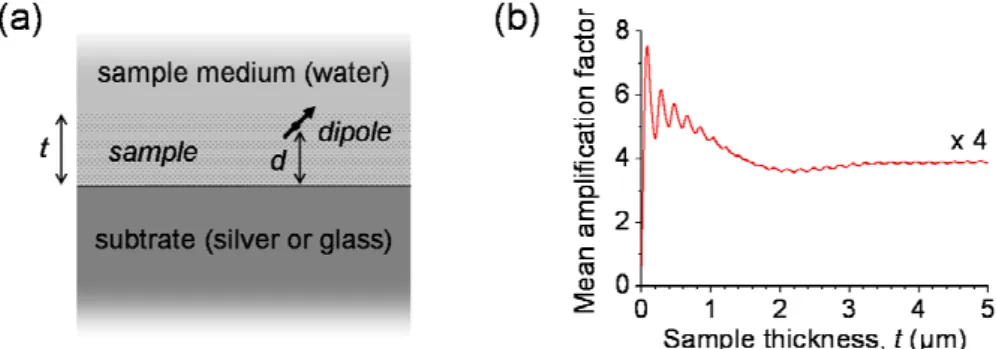
We initially wonder whether (and to what extent) the use of mirror substrates could help fluorophore detection when applied to micrometer-scaled objects such as biological samples. To respond this issue, we modelled an excited molecule as a point dipole oscillator, using a classical theory which was first developed by Chance et al,18 and then we adapted the model to a new system, which is depicted in Fig 4a. We considered a biological sample directly adsorbed on the substrate surface, immersed in an aqueous medium, and homogeneously stained with fluorophores. Sample and its medium refractive indices were assumed to equal that of water (n = 1.33). The substrate was equated with a semi-infinite space, a single interface being considered (glass/water or metal/water interface, depending on which case is examined). All the functions that depend on the distance to the substrate (excitation rate, radiative yield, radiation spatial pattern) were integrated over a given range of distance, corre-sponding to the thickness of the sample, assuming a uniform distribution of fluorophore-to-substrate distances. Besides, the model takes account of the loss of lateral resolution appearing at high NA. This alteration is due to the fact that a fraction of the optical rays, originating from a point emitter and collected through the objec-tive lens, virtually comes from the emitter mirror-image, which is not located in the focus plane but below the substrate surface. The complete description and commentary of this theoretical work can be found in Ref. (19).
Figure 4. Geometry of the modeled system, comprising a single interface between two semi-infinite media (the water-like sample medium and a glass or silver substrate), t standing for the sample thickness (a); theoretical variation of the signal mean amplification factor as a function of the sample thickness (b).
3.2 Results and Discussion
Figure 4b shows the theoretical amplification factor of the fluorescence signal, detected through a 0.4-NA objective lens, as a function of the sample thickness t. When mirror slides are applied to fluorescent imaging of thick samples, signal amplification can be ascribed to two complementary processes. First, the reflection of the excitation light off the slide surface enhances fluorophore excitation rate, which basically contributes a mean factor of two to the signal gain. Second, the emitted light is redirected by the mirror substrate toward the objective lens, thus increasing the collection efficiency (typically improved by twofold, the emission being isotropic on average). As a result, a fourfold amplification of the detected fluorescence signal is expected.
One may however point out a potential pitfall in the present technique. The standing wave pattern resulting from the incident and reflected beam interference could be detrimental to fluorophore detection, due to excitation field heterogeneity. However, no spatial modulation was found experimentally. In fact, this interference is shortened to a distance of a few micrometers when using broadband light sources and excitation filters. Moreover, incident light scattering and surface corrugation may contribute to shorten the excitation field coherence length and thus reduce its spatial modulation.
An additional advantage, ensuing from the improvement of the collection efficiency by twofold, is that twice as many emitted photons are detected before fluorophore photodestruction. This effect does not result from a mod-ification of the photobleaching rate, since fluorophore lifetime remains unchanged on average when considering an homogeneous distribution of molecules over a micrometer range of distances to the substrate. Nevertheless, this comes to an apparent photostabilization of the fluorescent probes.
4. BIOMEDICAL APPLICATIONS
4.1 Fluorescence Imaging of Epithelial Cells
We applied our method to fluorescence imaging of dog kidney cells.19 These are considered to be model subjects for the study of subcellular structures within epithelial cells, especially in the context of cancer research.20 Statistical studies carried out on epithelium cells allow evaluating the proportion of cells that exhibit an abnormal inner structure. Such studies require both a wide field of observation (i.e., low magnification) to get a reliable statistical population and a high contrast (i.e., high signal and signal/noise ratio) to achieve an accurate diagnosis. Experimental works were carried out to demonstrate the interest of metal-coated substrates, in tight collaboration with the Cell Imaging Platform of the Curie Institute (Orsay, France).
We formed a monolayer of dog kidney cells on a silver mirror slide (a microscope slide coated with a 60-nm-thick silver thin film). Cells were fluorescently tagged following the immunofluorescence technique described in Sec. 2.2. A set of three fluorescent labels was employed with the aim of imaging cell microtubules (eGFP), Golgi network (Alexa 633) and mitochondria (Mitotracker Red CMXRos) selectively. The resulting three fluorescence images were superimposed to form the false-color image presented in Fig. 5, a color being appointed to each of the three biomarkers (green for Alexa 633, blue for Mitotracker, and red for eGFP). Fluorescence signal was collected through a 20× 0.4-NA air objective, in an epi-illumination configuration. Before depositing cells on the mirror slide, a stripe of silver had been removed from the surface by scratching it with one strip of a sharp-ended plastic pair of tweezers.† The glass slide reveals itself in this area so that the signal brightness enhancement can
readily be observed.
When examining an area without cells (dark area at the top right-hand side quarter of Fig. 5), one can observe that the presence of the silver film produces a background signal of relatively low intensity compared to the noise level detected in the area without metal (dark horizontal stripe in Fig. 5). On the silver-coated part of the slide, both a raise of the fluorescent signal and a strengthening of the image contrast appear. One might be tempted to reply that such an image improvement could have been achieved in a more straight way by changing the air objective for an oil-immersion objective with higher NA and magnification. However, we would like to stress that this would result in a narrowed field of observation, whereas conjugating an air objective to a mirror slide contributes to reconcile high-sensitivity fluorescence detection and broad-field vision (up to two hundred
†Scratching the metallic coating can only be done when its adherence has not been improved by chromium
Figure 5. Dog kidney cells on a silver-mirror slide, fluorescence image in false colors. Red, green, and blue colors are respectively associated with cell microtubules, Golgi networks, and mitochondria. Fluorescence signal is detected through a 20× 0.4-NA air objective. A region of the substrate is deprived of silver (dark horizontal stripe) so that the sample is in direct contact with the glass surface. Measurements from this region are used as reference for enhancement factor calculation.
Figure 6. Magnification of a region of interest taken from Fig. 5 (white frame), exhibiting both a bare glass area (bottom half) and a silver-coated area (top half). Grey-level fluorescence images corresponding to the detected signal from cell microtubules (a), Golgi networks (b) and mitochondria (c).
cells can be examined simultaneously, in Fig. 5). Moreover, the use of oil immersion objectives is not as straight as it seems at first sight, when involved in repetitive operations, owing to the presence of oil and the extremely short working distance.21
Figure 6 shows a closeup of a region of interest, taken from Fig. 5 (area limited by a white dashed line), which top half is silver-coated (the glass slide is bare in its bottom half). The false-color image was split into three grey-level fluorescence images, each corresponding to one of the three signal channels (red, green, blue), to show microtubule (a), Golgi network (b), and mitochondrion (c) staining separately. In the silver-coated area, fluorescence appears to be enhanced for each of the three labels, which plaids for a spectrally broad effect. Since the method principle is based on the reflection of the incident and emitted light on metal-coated slides, an efficient amplification of the fluorescence signal over their whole spectral range of reflectivity indeed was expectable. Please note that this statement also implies that a poor efficiency is expected out of this range of reflectivity, e.g., when conjugating DAPI-tagging of cell nucleus to the use of gold-coated slides (gold strongly absorbs ultraviolet radiation). In that case, one should consider using aluminum-coated slides (the method remaining the same) to spectrally extend slide reflectivity to the near-UV range, to suit such an application.
Thanks to fluorescence signal amplification, more details can be perceived in the cell inner structure. Notably, a stronger contrast makes possible a more accurate spatial localization of mitochondria and Golgi apparatus. Furthermore, one can distinguish microtubule extremities from the background in the silver-coated area whereas cell’s contour can hardly be drawn in the bare-glass area.
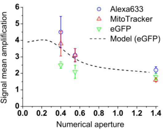
To evaluate the mean amplification factor brought about by the use of a silver mirror slide, we statistically studied the fluorescence signal variations over wide areas of the substrate, comprising more than one hundred cells, and for the use of three different microscope objectives (see technical details in Sec. 2.3). These experimental factors are shown in Fig. 7 as a function of the objective NA. Besides, we calculated the theoretical variation of the amplification factor, for a homogeneous distribution of eGFP fluorophores in a 5 µm-thick sample (see details about the model in Sec. 3.1). Experimental and theoretical results agree on the method efficiency at low NA. Small discrepancies between the experiment and the model ensue from the heterogeneous distribution of fluorophores in the biological sample, which feature was not taken into account in the model. At given conditions of observation (same NA), the mean amplification factors of the three biomarkers differ slightly, for the same reasons. Fluorescence signal mean value was found to be amplified by a factor ranging from 2.5 to 4.5, when using a 20× 0.4-NA air objective.
0.0 0.2 0.4 0.6 0.8 1.0 1.2 1.4 0 1 2 3 4 5 6 S i g n a l m e a n a m p l i f i c a t i o n Numerical aperture Alexa633 MitoTracker eGFP Model (eGFP)
Figure 7. Mean amplification factors of the fluorescence signal experimentally measured for Alexa 633 (◦), Mitotracker (4) and eGFP (5) fluorophores versus microscope objective numerical aperture, together with the theoretical variation of the amplification factor as calculated for a homogeneous distribution of eGFP fluorophores in a 5 µm-thick sample.
4.2 Fluorescence Imaging of Tissue and Cytogenetic Analysis for Biomedical Diagnosis
We applied mirror slides to tissue imaging for biomedical diagnosis.22 Our investigations were concerned with the follow-up of the microvessel repair in sex-mismatched human grafts. This study was carried out in tight collaboration with the Pathology Laboratory of Saint-Louis Hospital (Paris, France). Following a transplant, the way that the microvessels repair is considered to be a reliable indicator for graft acceptance/rejection. In a series
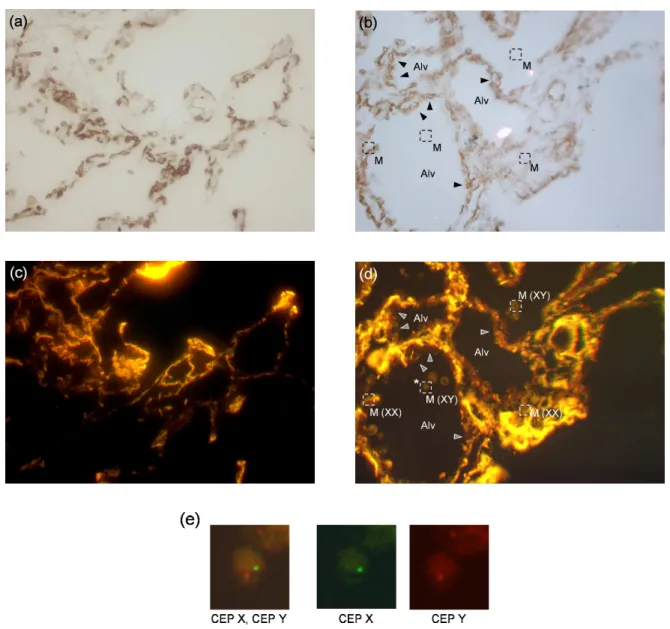
Figure 8. Application of mirror slides to tissue imaging for medical diagnosis. Fluorescence in situ hybridization (FISH) is performed to identify the X or Y-chromosome together with immunologic staining to characterize cell types on the same tissue section, cut from a biopsy made on a human lung graft (transplanted from a female donor to a male recipient). Bright-field transmission images (a,b) and fluorescence images (c,d) of the same tissue section, on a standard microscope slide (a,c) and on a gold-mirror slide (b,d). Images a and c (b and d) show the same field of view. Captions of images
b and d: M stands for Alveolar macrophages; XX and XY state cell gender; Alv stands for Alveoli; arrowheads point
at pulmonary capillaries. Cell origin, which is correlated with their gender, is determined from sexual chromosome identification, as shown in image e. Image e is a closeup of a region of interest from image d, centered on a alveolar macrophage (frame pointed out with an asterisk in image d). The dual-labeling of X and Y-chromosomes (CEP X / CEP Y) is decomposed so as to explicit the method. The co-localized presence of a green (X) and a red (Y) spot indicates the male gender (XY).
of biopsies, performed for diagnostic purpose in female lungs transplanted in male recipients, genotype analysis of endothelial cells was performed to determine the origin (donor or recipient) of endothelial cells involved in microvessel repair of the transplanted lung. X- and Y-chromosome detection by fluorescence in situ hybridization (FISH) and immunohistochemical staining were combined to characterize the endothelial cells and their genotype on the same tissue section23(see the methods described in Sec. 2.2).
A 5-µm-thick tissue section, cut from a paraffin-embedded sample, was deposited onto a gold-mirror slide (a microscope slide coated with a 70-nm-thick gold thin film). Figures 8a and b are bright-field images of this tissue section, on a bare glass area (a) and on a gold-coated area (b) of the slide, acquired in transmission. Remarkably, it is still possible to image the biological sample in transmission on the gold coated part of the slide, due to the precisely controlled thickness of the metal film (see commentary on mirror slide transmission in Sec. 2.2). Figures 8c and d are fluorescence images of the same respective areas than Fig. 8a and b. Fluorescence images were acquired in the same lightning conditions. Images in Fig. 8a to d were obtained using a 40× 0.4-NA microscope air objective.
In Fig. 8a and b, the contrast resulting from the tissue immunological staining allows one to visualize mi-crovessel lining and cell arrangement. Images are captioned with the name of the main functional elements. Pulmonary circulation, which brings and removes gases to and from the lung, begins with the main pulmonary artery, which branches in parallel with the bronchopulmonary tree. At the level of the terminal bronchioles, the arteries further divide to form an extensive bed of pulmonary capillaries (pointed out by arrowheads in Fig. 8b and d) that surrounds the lung alveoli (abbreviated as Alv. in Fig. 8b and d). Lung alveoli are one of the thin-walled, saclike terminal dilations of the respiratory bronchioles, alveolar ducts, and alveolar sacs across which gas exchange occurs between alveolar air and the pulmonary capillaries. Alveolar macrophages (abbreviated as M. and framed with a dashed line in Fig. 8d), often referred to as ”dust cells”, are vigorously phagocytic macrophages on the epithelial surface of lung alveoli where it ingests inhaled particulate matter.
The comparison between Fig. 8c and d reveals an amplification of the fluorescence signal on the gold-coated part of the slide, which can be ascribed to an improvement of both excitation and collection efficiencies (see theoretical discussion in Sec. 3.1). In the bare-glass part of the slide (Fig. 8c), the fluorescence contrast is too weak to detect the genetic probes, which precludes one from establishing cell origin (donor XX or recipient
XY ). Consequently, one is forced to change the microscope air objective for an oil-immersion objective of high
NA (and high magnification, inevitably) with all the above-mentioned drawbacks, among which are narrow field of observation and short depth of field (see Sec. 1). On the other hand, image brightness and contrast are raised up on the gold-coated part of the slide, allowing one to detect the genetic probes using an air objective with low-magnification and low NA. That way, cytogenetic information (cell gender determined from sexual chromosome identification, see Fig. 8e) and histological information (tissue architecture) are simultaneously available. As a result, the correlation links between the two levels of analysis, which are essential to biomedical diagnosis, instantaneously become obvious. Furthermore, the large depth of field of low-NA microscope objectives makes it possible to simultaneously probe the whole layer of the tissue section (the cut is 5-µm-thick).
5. CONCLUSION
The use of metal-coated substrates offsets the low NA of standard microscope air objectives with the reflection of the excitation field back through the sample and the redirection of the emitted light toward the objective lens, thus increasing both excitation and collection efficiencies. That way, broad areas of micrometer-thick biological samples can be imaged in fluorescence microscopy with enhanced brightness and contrast, while keeping practical advantages of dry optics (absence of immersion oil, relatively large work distance).
The present technique is really easy to implement since metal-coated substrates can be used on all fluorescence microscopes and imaging devices, provided that they involve an epifluorescence configuration. Fluorescence detection sensitivity can be greatly improved just by replacing the usual microscope glass slide by an active substrate, with no need for additional material. Thanks to a surface treatment (protective coverlayer), clinicians and biologists can moreover keep on preparing cell and tissue samples on-slide, following usual biochemical protocols. The use of mirror substrates is furthermore a non-expensive solution since all their manufacturing involved widespread techniques. Consequently, very few supplementary development would be required to start mass production.
APPENDIX A. FLUOROPHORE AND FILTER CHARACTERISTICS
Abs. and Fluo. respectively stand for the wavelengths of fluorophore maximal optical extinction and fluorescence
emission. Exc., Dichr. and Bar. are abbreviations for exciter filter, dichroic mirror and barrier filter. Microscope cube commercial references (Ref.) are specified in the forth column of Tab. 1 and Tab. 2. Fifth to seventh columns report the central wavelengths and the bandwidths of the exciter and barrier bandpass (BP) filters, and the cutoff wavelength of the dichroic mirror. In Tab. 2, barrier filters are high-pass filters. All wavelength values are given in nanometers.
Table 1. Fluorescent biomarkers and microscope filters for applications to fluorescence imaging of dog kidney cells.
Fluorescent biomarker Microscope cube
Name Abs. Fluo. Ref. Exc. Dichr. Bar.
eGFP 489 508 Leica L5 BP 480/40 505 BP 527/30 Mitotracker 579 599 Leica N3 BP 546/12 565 BP 600/40 Alexa 633 632 647 Leica Y5 BP 620/60 660 BP 700/75
Table 2. DNA fluorescent probes and microscope filters for applications to cytogenetic analysis using FISH technique.
DNA fluorescent probe Microscope cube
Name Abs. Fluo. Ref. Exc. Dichr. Bar.
CEP X 500 530 Olympus U-MWIB BP 475/30 505 515 CEP Y 560 590 Olympus U-MWIG BP 535/30 565 580
ACKNOWLEDGMENTS
This work was supported by the French research ministry and the National Center for Scientific Research (CNRS) through the Nanoscience-Nanotechnology program.
REFERENCES
1. J. W. Lichtman and J.-A. Conchello, “Fluorescence microscopy,” Nat. Methods 2(12), pp. 910–919, 2005. 2. J. Lippincott-Schwartz and G. H. Patterson, “Development and use of fluorescent protein markers in living
cells,” Science 300(5616), pp. 87–91, 2003.
3. C. Seydel, “Quantum dots get wet,” Science 300(5616), pp. 80–81, 2003.
4. J. K. Jaiswal, H. Mattoussi, J. M. Mauro, and S. M. Simon, “Long-term multiple color imaging of live cells using quantum dot bioconjugates,” Nat. Biotechnol. 21(1), pp. 47–51, 2003.
5. D. Axelrod, “Total internal reflection fluorescence microscopy in cell biology,” Traffic 2(11), pp. 764–774, 2001.
6. D. J. Stephens and V. J. Allan, “Light microscopy techniques for live cell imaging,” Science 300(5616), pp. 82–86, 2003.
7. J.-A. Conchello and J. W. Lichtman, “Optical sectioning microscopy,” Nat. Methods 2(12), pp. 920–931, 2005.
8. S. Inoue and R. Oldenbourg, “Microscopes,” in Handbook of Optics, pp. 6325–6331, McGraw-Hill, New York, 2nd ed., 1995.
9. P. Perlman in Basic Microscope Techniques, Chap. I, pp. 24–25, Chemical Publishing Company, New York, 1971.
10. B. Liu, S. Li, and J. Hu, “Technological advances in high-throughput screening,” Am. J.
11. V. C. Abraham, D. L. Taylor, and J. R. Haskins, “High content screening applied to large-scale cell biology,”
Trends Biotechnol. 22(1), pp. 15–22, 2004.
12. H. Moch, J. Kononen, O.-P. Kallionimeni, and G. Sauter, “Tissue microarrays: What will they bring to molecular and anatomic pathology?,” Adv. Anat. Pathol. 8(1), pp. 14–20, 2001.
13. P. B. Johnson and R. W. Christy, “Optical constants of the noble metals,” Phys. Rev. B 6(12), pp. 4370– 4379, 1972.
14. F. M. Coquelle, M. Caspi, F. P. Cordelieres, J. P. Dompierre, D. L. Dujardin, C. Koifman, P. Martin, C. C. Hoogenraad, A. Akhmanova, N. Galjart, J. R. De Mey, and O. Reiner, “Lis1, clip-170’s key to the dynein/dynactin pathway,” Mol. Cell. Biol. 22(9), pp. 3089–3102, 2002.
15. C. Infante, F. Ramos-Morales, C. Fedriani, M. Bornens, and R. M. Rios, “Gmap-210, a cis-golgi network-associated protein, is a minus end microtubule-binding protein,” J. Cell Biol. 145(1), pp. 83–98, 1999. 16. T. M. Savino, J. Gebrane-Younes, J. De Mey, J.-B. Sibarita, and D. Hernandez-Verdun, “Nucleolar assembly
of the rrna processing machinery in living cells,” J. Cell Biol. 153(5), pp. 1097–1110, 2001.
17. J.-B. Sibarita, H. Magnin, and J. De Mey, “Ultra-fast 4d microscopy and high throughput distributed deconvolution,” Proc. IEEE Int. Symp. Biomed. Imag. , pp. 769–772, 2002.
18. R. R. Chance, A. Prock, and R. Silbey, “Lifetime of an emitting molecule near a partially reflecting surface,”
J. Chem. Phys. 60, pp. 2744–2748, 1974.
19. E. Le Moal, E. Fort, S. L´evˆeque-Fort, F. P. Cordeli`eres, M.-P. Fontaine-Aupart, and C. Ricolleau, “Enhanced fluorescence cell imaging with metal-coated slides,” Biophys. J. 92(6), pp. 2150–2161, 2007.
20. J. M. Vasiliev, T. Omelchenko, I. M. Gelfand, H. H. Feder, and E. M. Bonder, “From the cover: Rho overexpression leads to mitosis-associated detachment of cells from epithelial sheets: A link to the mechanism of cancer dissemination,” Proc. Natl. Acad. Sci. USA 101(34), pp. 12526–12530, 2004.
21. P. James, “The oil immersion objective,” Micscape Magazine 77, March 2002.
22. E. Le Moal, E. Fort, S. L´evˆeque-Fort, A. Janin, H. Murata, F. P. Cordeli`eres, M. P. Fontaine-Aupart, and C. Ricolleau, “Mirror slides for high-sensitivity cell and tissue fluorescence imaging,” J. Biomed. Opt. 12(2), p. 024030, 2007.
23. V. Meignin, J. Soulier, F. Brau, M. Lemann, E. Gluckman, A. Janin, and G. Socie, “Little evidence of donor-derived epithelial cells in early digestive acute graft-versus-host disease,” Blood 103(1), pp. 360–362, 2004.