Publisher’s version / Version de l'éditeur:
Vous avez des questions? Nous pouvons vous aider. Pour communiquer directement avec un auteur, consultez la première page de la revue dans laquelle son article a été publié afin de trouver ses coordonnées. Si vous n’arrivez pas à les repérer, communiquez avec nous à PublicationsArchive-ArchivesPublications@nrc-cnrc.gc.ca.
Questions? Contact the NRC Publications Archive team at
PublicationsArchive-ArchivesPublications@nrc-cnrc.gc.ca. If you wish to email the authors directly, please see the first page of the publication for their contact information.
https://publications-cnrc.canada.ca/fra/droits
L’accès à ce site Web et l’utilisation de son contenu sont assujettis aux conditions présentées dans le site LISEZ CES CONDITIONS ATTENTIVEMENT AVANT D’UTILISER CE SITE WEB.
Research Paper (National Research Council of Canada. Division of Building
Research), 1968-01-01
READ THESE TERMS AND CONDITIONS CAREFULLY BEFORE USING THIS WEBSITE.
https://nrc-publications.canada.ca/eng/copyright
NRC Publications Archive Record / Notice des Archives des publications du CNRC :
https://nrc-publications.canada.ca/eng/view/object/?id=428d9531-8e59-4efd-9c7e-9afda756f736
https://publications-cnrc.canada.ca/fra/voir/objet/?id=428d9531-8e59-4efd-9c7e-9afda756f736
NRC Publications Archive
Archives des publications du CNRC
This publication could be one of several versions: author’s original, accepted manuscript or the publisher’s version. / La version de cette publication peut être l’une des suivantes : la version prépublication de l’auteur, la version acceptée du manuscrit ou la version de l’éditeur.
For the publisher’s version, please access the DOI link below./ Pour consulter la version de l’éditeur, utilisez le lien DOI ci-dessous.
https://doi.org/10.4224/40000444
Access and use of this website and the material on it are subject to the Terms and Conditions set forth at
Pressure differences caused by chimney effect in three high buildings
and Building pressures caused by chimney action and mechanical
ventilation
Ser
TH1
N21r2
no.
346
c.2
BLDG
I i ' INATIONAL RESEARCH COUNCIL O F CANADA
CONSEIL NATIONAL DE RECHERCHES DU CANADA
PRESSURE DIFFERENCES CAUSED BY CHIMNEY E F F E C T
IN THREE HIGH BUILDINGS
and
BUILDING PRESSURES CAUSED BY CHIMNEY ACTION
AND MECHANICAL VENTILATION
by
G. T. Tamura and A. G. Wilson
Reprinted from
American Society of Heating, Refrigerating and Air-Conditioning Engineers,
Inc.TRANSACTIONS
Vol. 73, Part
11,
1967
Research Paper No. 346
of the
@irision of Building Research
Price 50 cents
OTTAWA
January 1968
DIFFERENCES DE PRESSIONS ENGENDREES PAR L'EFFET
DE TIRAGE DANS TROlS EDIFICES ELEVES
SOMMAIRE
Les auteurs exposent les re'sultats de recherches mene'es s u r place en
vue de mesurer les fuites totales d'air et la repartition des pressions
engendrke par l'effet de tirage, tant seul qu'en conjonction avec l'ap-
pareillage de ventilation des immeubles. La r6gion des a i f i c e s o~ la
pression interne egalait la pression externe atteignait de 35
5
52 pour
cent de leur hauteur. Les diffe'rences de pressions de part et d'autre des
entrees e'taient plus faibles lors de l'arrst de l'appareillage de ventilation
que le manuel de I'ASHRAE ne permettait de les calculer, en raison de la
faible altitude de la re'gion
2
diffe'rence pi6zome'trique nulle et des impor-
tantes pertes de pression a w plafonds du rez-de-chausse'e. La proportion
centesimale
du
tirage reel par rapport au tirage calcul6 atteignait entre
0.63 et 0.82.
PRESSIONS CAUSEES PAR L'EFFET DE TIRAGE E T LA
VENTILATION MECHANIQUE DANS LES BATIMENTS
SOMMAIRE
Le pre'sent article communique les re'sultats d'une e'tude s u r la rgpartition
des differences de pressions engendre'es par l'effet de tirage et la venti-
lation mkchanique. Les auteurs s e sont servis pour cette 6tude d'un
modzle mathe'matique repre'sentant
un bstiment. 11s ont d6termin6 les
effets de variations d76tanch6it6 des
murs
ext6rieurs et des cloisons et
du
nombre des planchers s u r la repartition des pressions. 11s ont e'gale-
ment 6tudi6 la manizre par laquelle 1'6tablissement de diff6rences de
pressions uniformes ou non affecte la r6partition des pressions causkes
par l'effet de tirage.
Ces donne'es fournissent la base de la pr6vention des fuites d'air c a u s k s
par l'effet de tirage. Elles aident 6galement
2
interpr6ter les mesures pra-
tiques contenues dans l'article conjoint intitul6 "lDiff6rences de pressions
- -No. 2046
G. T. TAMURA
Member ASHRAE A. G. WILSON
Member ASHRAE
Pressure Differences Caused by Chimney Effect
in Three High Buildings
Air flows into and out of buildings under buoyancy ported.' This paper gives the results of subse- forces resulting from differences between inside quent measurements on three buildings of 17, 34 and outside temperatures. This chimney effect in- and 44 stories.
creases with temperature difference and the height
of the building, and i s therefore one of the major INSTRUMENTATION
causes of a i r leakage in tall buildings during the winter. There a r e a number of important implica- tions of a i r leakage; 1 infiltration at entrances and
its effect on heating load i s one of special interest to the air-conditioning engineer.
The total theoretical draft o r pressure differ- ence resulting from chimney action can be com- puted easily; values a r e given graphically in the ASHRAE HANDBOOK OF FUNDAMENTALS.~ The distribution of this theoretical draft across exterior walls and internal separations depends upon the r e
-
lative resistances to flow through these elements. Some information on these relations has been de- veloped analytically,3 but for purposes of design calculations data a r e required on the actual a i r leak- age characteristics of buildings as constructed. This type of information can only be obtained o r inferred by measurement.Field studies were therefore undertaken on several multi-story buildings to obtain overall air leakages and the patterns of pressure differences caused by chimney action, both alone and in com- bination with pressure differences induced by the operation of ventilation systems. Results of meas- urements of a nine-story building have been r e -
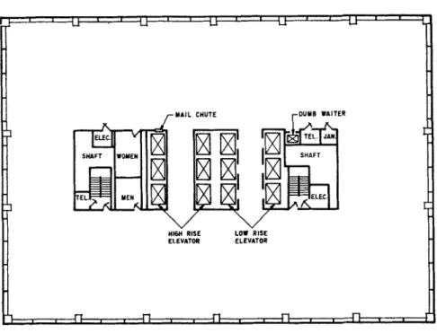
Information on the three test buildings i s given in Table I. Building A (44-story) and Building B (34- story) a r e commercial office buildings located in Montreal, Canada (Figs. 1 and 2). Building C (17- story) i s a government office building located in Ottawa, Canada (Fig. 3). Typical floor plans of each building a r e given in Figs. 4, 5 and 6. All a r e rectangular in shape, with stairwells, eleva- tors and various services located in the core of the buildings. Buildings A and B have two main mechanical equipment floors, one at the top and the other on an intermediate level. Building C has only one, located a t the top floor level. The sup- ply, return and exhaust fans a r e located on these floors, with inlet and exhaust openings in the ex- terior walls. The mechanical equipment rooms serving the first and basement floors a r e located in the basements. In Building A, the mechanical equipment room serving the first floor i s located on the f i r s t floor mezzanine.
In Buildings A and B, outside static pressure taps of 1/4-in. copper tubing were installed in the middle of each wall of the two mechanical equip- ment floors, 2 ft above the floor level and flush with the outside surface of the exterior walls. To G . T . Tamura i s a Research Officer, and A. G . Wilson i s obtain a typical inside pressure, the inside p r e s - Headof Building Services Section, Div. of Building Research, s u r e taps were located two floors away from the National Research Council, Ottawa, Canada. This paper was mechanical equipment floors. In Building A these prepared for presentation at the ASHRAE 74th ~ n i u a l Meet- taps were located in the suspended ceiling of the ing, Minneapolis, Minn., June 26-28, 1967. It i s a con-
tribution from the Division of Building Research, National 18th and 40th floors and were associated with the Research Council, Canada and i s published with the approval outside pressure taps of the 16th and 43rd mech- of the Director of the Division. anical equipment floors, respectively. The p r e s -
F i g . I B u i l d i n g A F i g . 2 B u i l d i n g B
s u r e recording system was located in the 43rd mechanical equipment floor. The inside and out- side static p r e s s u r e taps were connected to the two multiple p r e s s u r e switches of the recording system with 1/4-in. LD plastic tubing. The output ports of p r e s s u r e switches were connected to a strain-gauge diaphragm-type p r e s s u r e transducer (sensitivity 0.002 in. of water). The p r e s s u r e tubes from the lower floors were strung through the conduit openings in the electrical rooms to the recording equipment.
The inside and outside static p r e s s u r e taps and thepressure recording system were installed in the same way in Buildings B a s they were in Building A. The outside p r e s s u r e taps were located in the exterior walls of the 11th and 34th mechanical e - quipment floors, the inside p r e s s u r e taps in the suspended ceilings of the 9th and the 32nd floors. The pressure recording system was located in the
11th mechanical equipment floor.
In Building C, the inside and outside static p r e s s u r e taps were located at the middle of each wall of the 2nd, 6th, 10th and 15th floors. The out- side static tap was installed underneath the bottom of the window frame, and the inside static p r e s - s u r e tap in the suspended ceiling space. The p r e s - s u r e tap connections were made with 3/16-in. ID plastic tubing, with the tubes strung vertically through the hollow mullions of the exterior walls to
the 15th floor, across the 15th floor suspended ceiling space and up the service shaft in the core of the building to the pressure recording system located on the 17th mechanical equipment floor.
P r e s s u r e differences across building entran- ces and various interior partitions were measured with a portable p r e s s u r e meter.
Wind velocity for both Montreal buildings (A and B) was measured with a cup-type anemometer located on a mast on Building A about 800 ft above street level. In Ottawa, the anemometer was lo- cated on a temporary mast 15 ft above Building C. RESULTS AND DISCUSSION
P r e s s u r e measurements to investigate chimney ef- fect were conducted over a range of outside a i r temperatures when the buildings were unoccupied. To minimize the effect of wind, they were taken with wind speed under 10 mph.
Measurements for the three buildings, with ventilation systems off, a r e illustrated in Figs. 7, 8 and 9. Outside supply and exhaust dampers in the equipment rooms were closed; in Building C these dampers were sealed with plywood or plastic sheet. L ~ c a t i o n of the mechanical equipment floors i s indicated. P r e s s u r e differences across the'ex- terior walls were measured at the outside pres- s u r e taps: at two levels in Buildings A and B and
from values of the pressure difference across floors; these were obtained from measurements made internallv across the stairwelldoors as pre- viously described.
In Figs. 7, 8 and 9, the slope of the lines r e - presenting exterior wall pressure differences be- tween floors i s the same a s that of the line repre- senting the theoretical draft; the horizontal line a t each floor represents the pressure drop across it.3 The sum of the pressure differences across the floors represents the pressure loss within the building, o r the difference between the actual draft acrocs exterior walls and the theoretical chimney draft
.'
Neutral zone levels were approximately 40, 35 and 52% of the building height for ~ u i l d i n ~ s A, B and C, respectively. Measurements made over a range of outside temperatures indicated that these levels were not much affected by temperature. Pressure differences across exterior walls at dif- ferent temperatures were approximately in pro- portion to the corresponding theoretical draft due to chimney action. For example, at -10 F outside the pressure difference across the 41st floor of Building A was about 0.75 in. of water; across the 32nd floor of Building B it was about 0.55 in.
With the exception of the large pressure dif- ferences across the ceiling of the first floor (a of Fig. 7) and the floor of the upper mechanical e - quipment room (b of Fig. 7), the pressure differ- ences across floors of Building A were relatively uniform. The ratio of actual to theoretical draft between these levels was about 0.88, which indi-
F i g . 3 B u i l d i n g C cates a relatively low resistance to.vertica1 flow
of a i r within the building;3 with theventilation sys- four levels in Building C. In addition, pressure tem off, the supply and return a i r ducts represent- differences across the main entrance of eachbuild- ed relatively large interconnections between floors. ing were measured. Pressure differences across In the mid-height region pressure differences a - the exterior walls at other levels were calculated c r o s s several floors were nearly zero.
r MAIL CHUTE
ELEVATOR ELEVAlOR ELEVATOR
F i g . 4 T y p i c a l f l o o r plan o f B u i l d i n g A
Description of T e s t Buildings Height Building A 592 ft Building B 430 ft Building C 219 ft No. of floors above ground No. of basement floors F l o o r dimensions Typical floor height Volume above ground F i r s t floor volume Outside wall a r e a above ground F i r s t floor outside wall a r e a Building f r a m e E x t e r i o r walls Windows
100 ft 0 in. x 140 ft 0 in. 116 ft 10 in. x 172 ft 10 in. 88 ft 0 in. x 140 ft 0 in. 12 ft 5 in. 11 ft 8.75 in. 11 ft 0 in.
Structural s t e e l Structural s t e e l Structural s t e e l
Reinforced concrete Aluminum spandrel panel P r e c a s t concrete panel s p a n d r e l faced with with fibreglass insulation backed with rigid g r e e n s l a t e and backed backed with rigid insula- insulation
with rigid insulation tion
Sealed double glazed, Sealed double glazed, Sealed double glazed,
fixed fixed fixed and horizontally
pivoted casement window Air-conditioning s y s t e m P e r i m e t e r s y s t e m with
high p r e s s u r e induction units and i n t e r i o r zone
units Same Same
The reduction in p r e s s u r e differences a c r o s s the e x t e r i o r walls a t t h e f i r s t floor (c of Fig. 7) level r e l a t e s t o the increased e x t e r i o r leakage a r e a f r o m entrances a t this level. T h e r e was, c o r r e s - pondingly, a n i n c r e a s e in the p r e s s u r e differences a c r o s s the entrances t o the v e r t i c a l s h a f t s a t t h e s e levels. The l a r g e p r e s s u r e difference a c r o s s the second s t o r y floor (a of Fig. 7) suggests a good separation between f i r s t and second f l o o r s . T h e f i r s t , o r main floor, had a s e p a r a t e air-condition- ing s y s t e m s o that t h e r e was no interconnection by this means. T h e r e was a l s o a reduction in p r e s - s u r e differences a c r o s s walls of the 42nd and 43rd mechanical equipment room (d and e of Fig. 7) floors. Intake and exhaust openings occurred on these floors and c r a c k s around the closed d a m p e r s apparently provided a relatively low r e s i s t a n c e f o r a i r flow t o outside. T h e l a r g e p r e s s u r e difference a c r o s s the 42nd s t o r y floor (b of Fig. 7) suggests
good separation between that s t o r y and the 41st.
T h e low p r e s s u r e difference a c r o s s the exteri- o r wall of the 43rd s t o r y w a s accompanied by a l a r g e p r e s s u r e d i f f e r e n c e a c r o s s the stairwell (f of Fig. 7). T h e distribution of p r e s s u r e differences . a c r o s s the walls of the v e r t i c a l shafts indicates that most of the inflow occurred a t the f i r s t and base- ment levels. Most of the outflow f r o m the s t a i r - well occurred on the top mechanical equipment floors. Summation of the p r e s s u r e l o s s e s for the flow path from inside to outside through the s t a i r - well betweenfirst and40th floors indicates that the p r e s s u r e l o s s in the s t a i r w e l l w a s about 0.06 in. of w a t e r f o r the conditions of Fig. 7. This a g r e e s with values obtained by direct m e a s u r e m e n t . The p r e s s u r e l o s s in the high r i s e elevator, obtained by a s i m i l a r summation, was only 0.015. T h e dif- ference may be related to the higher p r e s s u r e loss a c r o s s the door of the elevator shaft on the f i r s t floor.
r Y A I L CHUTE ,-DUMB WAITER
H16n RISE LOW RISE
ELEVATOR ELEVATOR
Fig. 5 Typica.1 floor plan o f Building B
ences for Building B, shown in Fig. 8, is similar to that for Building A. Supply and return a i r ducts again provided interconnections between stories s o that pressure differences across floors were gen- erally small. An exception i s the floor of the 22nd story (a of Fig. 8), which was served by the mech- anical equipment room on the 34th story while the 21st story was served by the one on the 11th floor. The reduced pressure difference across the exterior of the second basement (b of Fig. 8) re- sulted Irom leakage under doors to an underground parking garage. There was good separation be- tween the first and second basements,
as
indicated by the large pressure difference across the inter- vening floor (c of Fig. 8). The relatively high pressure difference across the exterior walls of the first story and the correspondingly smaller pressure drop across the floor between first and second stories, were probably due to a relativelytight entrance and a low resistance to flow into floors above, through the ducts of the air-con- ditioning system. The reduced pressure difference across the exterior wall of the 34th floor mechani- c a l equipment room (d of Fig. 8) indicates a great- er opening to outside than on adjacent floors. The large pressure drop between the 33rd and 34th stories (e of Fig. 8) suggests a tight separation.
There i s an unusual pressure difference pat- tern in the lower part of the stairwell (f of Fig. 8), resulting from the influence of a door in the s t a i r - well between the first and second stories. The r e - sistance imposed by this door caused a i r , which entered the stairwell from the second basement level, to flow out to the first basement and first story levels. From the second story upwards, the pressure pattern for the stairwell was normal, with flow in a t lower levels and out at higher ones. The pressure loss in the stairwell betweenthe s e c -
F i g . 6 T y p i c a l floor plan o f Building C
4 4
-
I I I I I I-
-
-
LEGEN 0-
.Exterior wall-
o Stairwell-
high rise elevator
I
&Mid rise elevator-
m .LOW rise elevator
-
-
-
-
-
--
- "7 --
= O 241
Air flow out o f Air flow into
-
-
-
building and-
-
-
P R E S S U R E DIFFERENCE. IN. O F W A T E R F i g . 7 Pressure differences caused by chimney
effect
-
Building Aond and 33rd floors was about 0.06 in. of water, corresponding to that in Building A; the p r e s s u r e loss in the high-rise elevator shaft was about the s a m e . The resistance to flow between most floors is quite low with the air-conditioning system off. The ratio of actual t o theoretical draft between second and 21st floors is About 0.82, and between 22nd and 33rd floors about 0.91.
P r e s s u r e patterns for Building C, Fig. 9, a r e quite uniform. P r e s s u r e differences a c r o s s the floors w e r e v e r y s m a l l except near the bottom and top of the building where t h e r e w e r e l a r g e r leakage openings to outside through entrance doors on f i r s t and basement floors and around supply and exhaust dampers to outside on the 17th floor. The in- creased p r e s s u r e difference between 15th and 16th floors and the corresponding reduction in p r e s s u r e a c r o s s the exterior walls of the 16th floor (a of Fig. 9) may have been caused by increased leak- age to outside around doors leading to a n open bal- cony. The r a t i o of actual to theoretical draft be- tween second and 17th floor is about 0.9.
Figs. 10, 11 and 12 show the p r e s s u r e differ- ence pattern with the ventilation system operat
-
ing. The exterior .wall p r e s s u r e differences, with the ventilation system off, a r e superimposed on these graphs for comparison. In Building A theP R E S S U R E OIFFERENCE. IN. O F W A T E R F i g . 8 Pressure differences caused by chimney effect
-
Building Bp r e s s u r e readings w e r e recorded with one of four supply fans serving the 29th to the 41st floors shut down f o r repair. It was not practicable to estimate the net supply o r exhaust for individual floors. The ventilation s y s t e m s were operated normally. Thepattern of p r e s s u r e differences a c r o s s ex- t e r i o r walls of Building A w e r e not greatly affected by the operation of the ventilation system, indicat- ing that there was little net supply o r exhaust over the height of the building. In Building B the p r e s - s u r e difference curve was shifted to the left, by 0.15 to 0.22 in. of water, indicating a significant pressurization of a l l floors with a corresponding lowering of the neutral zone level.
Pressurization of Building C varied between 0.01 and 0.06 in. of water. With the ventilation s y s t e m operating, the p r e s s u r e differences a c r o s s the various internal separations w e r e increased. This resulted, in part, f r o m increased resistance to upward a i r flow in thebuilding when the ventila- tion system no longer provided a connecting path between floors. In some instances there w e r e in- c r e a s e d p r e s s u r e d i f f e r e n c e ~ a c r o s s the floors from variation in excess supply o r exhaust be- tween floors. This is evident, for example, in the vicinity of the 29th floor of Building A (a of Fig.
lo), above which there appears to have been a s m a l l excess of exhaust over supply.
A s i m i l a r imbalance occurred in the vicinity of the 22nd floor of Building B (a of Fig. 11). In Building C variations in excess supply w e r e quite random over the height of the building. T h e r e is a distortion of the pattern of p r e s s u r e differences a c r o s s the exterior walls a t the mechanical equip-
ment room floors (a of Fig. 12), which did not have the s a m e a i r supply o r exhaust a s adjacent floors. This i s most pronounced in Building A (b of Fig. 10) where a i r was exhausted from the equipment rooms; in addition, there w e r e large openings on the 42nd and 43rd floors t o provide combustion a i r for the heating boilers.
The r a t i o of actual to theoretical draft i s a m e a s u r e of the relative resistance to flow by chim- ney action of openings in the exterior enclosure and within the building. The r a t i o has little meaning, however, if t h e r e i s a significant variation of net supply o r exhaust from floor tofloor. Values of the r a t i o w e r e , therefore, computed only for p a r t s of the building height where net supply o r exhaust a p - peared to be fairly uniform. F o r Building A the values varied between 0.63 and 0.82; for Buildings B and C they w e r e 0.82 and 0.77, respectively. T h e s e w e r e significantly l e s s than w e r e obtained with the ventilation system off, indicating a higher resistance to flow from floor to floor when the ven- tilation system was operating.
Fig. 13 shows the a i r leakage c h a r a c t e r i s t i c s of the exterior enclosures of the three buildings. In Buildings B and C these w e r e obtained by opera- ting different numbers of supply fans, with exhaust fans turned off. The f r e s h and r e t u r n a i r d a m p e r s to the supply fans w e r e manually adjusted to give maximum outside a i r . In Building A the exhaust f a n s w e r e left on and the various supply fans w e r e turned off in turn. The outside d a m p e r s of a l l non- operating fans w e r e in a closed position for the three buildings. The net supply o r exhaust of out-
F i g . 9 Pressure d i f f e r e n c e s c a u s e d by chimney e f f e c t
-
Building C.
E x t e r i o r w a l l A S e r v i c e elevator 6 F r e i g h t elevator N e u t r a l zone l e -0.30 -0.20 -0.10 0 0.10 0.20 0.30 PRESSURE DIFFERENCE. I N . OF WATERs i d e a i r for each building was estimated from man- ufacturers' fan ratings. E r r o r s in the estimates may, therefore, occur due to uncertainties in the ratings and in the system characteristics. It i s possible that these e r r o r s , together with the e r r o r s caused by a i r leakage past the closed r e t u r n damp- e r s , might have resulted in an overestimation of the quantity of outside supply a i r . T h e leakage a r e a of the closed outside d a m p e r s would r e p r e s e n t additional openings, resulting in higher leakage values f o r the exterior wall.
With the buildings subjected to chimney action, t h e r e was a v a r i a t i o n in p r e s s u r e difference a c r o s s the enclosure f r o m top to bottom and average values w e r e used in constructing Fig. 13. In Building B the amount of pressurization was g r e a t - e r with the outside a i r a t 32 F than a t 65 F. This i s probably a r e s u l t of non-linear flow c h a r a c t e r - i s t i c s of leakage paths in the enclosure. T h e r e i s a l s o the possibility that leakage c h a r a c t e r i s t i c s of the exterior enclosure w e r e affected by outside temperature.
Leakage values in Fig. 13, given in t e r m s of cfm/sq ft of e x t e r i o r wall, appear to be relatively high for modern curtain wall construction. Stand- a r d s of the National Assn. of Architectural Metal
F i g . 1 0 Pressure d i f f e r e n c e s caused by chimney
e f f e c t and ventilation s y s t e m operation
-
Building AE x t e r i o r w a l l
V e n t . s y s t e n ~ o n V e n t . system o f f
-0.40 -0.30 - 0 . 2 0 -0.10 0 0.10 0.20 0.30 0.40 PRESSURE DIFFERENCE. I N . OF W A T E R
(814 -0.40 -0.30 -0.20 -0.10 0 0.10 0.20 0.30 0.40 P R E S S U R E DIFFERENCE, IN. O F W A T E R
-
-
A Exterior wall-
-
o Stairwell-
o AHigh rlse elevator-
A rn L o w rlse elevator-
-
0 O A T-
34 F-
-
-
-
--
-
-
-
-
-
-
-
-
-
Vent system o f f-
Exter~or wallF i g . 11 Pressure differences caused by chimney effect a n d ventilation system operation
-
Building BManufacturers call for a maximum leakage of 0.06 cfm/sq ft at a p r e s s u r e difference of 0.3 in. of water through curtain wall test specimens, exclu- sive of leakage through operable windows. The r e - sults indicate that there may be a large discrep- ancy between leakage values obtained on test speci- mens and those that apply to abuilding a s construc- ted. Leakage values obtained for a masonry c u r - tain wall1 were considerably higher than any of those shown in Fig. 13. The average leakage val- ues of the exterior wall for each story, expressed in t e r m s of the equivalent sharp-edged orifice a r e a , fall between 2.5 and 4.5 s q ft for the three buildings.
Because of the desirability of minimizing a i r leakages a t entrances, p r e s s u r e differences from chimney action across the exterior walls of the f i r s t floor a r e of special interest. Fig. 14 shows the p r e s s u r e differences caused by chimney effect a t the entrance level for the three buildings with ventilation systems off; these p r e s s u r e differences would be somewhat less if the ventilation system had not increased the interconnection between floors. The values of natural draft factor for en- trance, defined as the ratio of p r e s s u r e difference a c r o s s entrance over theoretical draft, were 0.22, 0.27 and 0.39 for Buildings A, B and C, respec- tively. Ref 4 gives a value of 0.7 for conventional buildings and of 0.3 for one building having tightly sealed windows.
The p r e s s u r e patterns resulting from pressur- ization of the first floor to balance the p r e s s u r e difference a c r o s s the entrance can be simulated by
-
-
-
-
-
-
-
d --
Vent system on Vent. system o f f
-
-
-
-
-
-
-
-
-0.30 -0.20 -0.10 0 0.10 0.20 0.30
PRESSURE DIFFERENCE, IN. O F W A T E R F i g . 1 2 Pressure differences caused by chimney effect and ventilation system operation
-
Building Cholding entrance doors open. This i s illustrated for Building B in Fig. 15. Similar results were obtained for Buildings A and C . The first floor p r e s s u r e was essentially the same a s that outside. P r e s s u r e differences a c r o s s the first floor ceil- ing and elevator doors were increased, a s expec- ted: a manifestation of increased a i r infiltration.
F i g . 1 3 Amount of pressurization with outside air
supply I- Y 0.6
-
5
U 0.4 i -1 CL CL 3 0.2 V) LT-
4 0 0 . 1 0.2 0.3 0.4 0.5 0.6 0.7 0.8F i g . 1 4 P r e s s u r e d i f f e r e n c e a - c r o s s e n t r a n c e c a u s e d b y c h i m - n e y e f f e c t
P r e s s u r e difference across upper floors and ele- vator doors was also increased, but to a lesser extent. The effect of the door in the stairwell be- tween first and second floors in reducing a i r leak- age into the stairwell i s also illustrated. A s i m - ilar effect was obtained in Building C, where a separate enclosure was constructed around the freight elevator. This reduced the pressure drop across the elevator door by about one half.
CONCLUSION
With the ventilating system turned off, ducts pro- vide interconnection between floors and affect the resistance to flow from floor to floor. The ratio of actual to theoretical draft under this condition, therefore, does not give a good index of the rela- tive resistance of openings in the exterior walls
where A i s the equivalent sharp-edged orifice a r e a
S
of leakage paths between floors provided by verti- cal shafts, and A is the same equivalent a r e a for
W
leakage paths in the exterior wall associated with each story.
With the ventilating system operating it i s im- probable that there will be a balance of supply and exhaust a i r on each floor, o r even a uniform net supply o r exhaust from floor to floor. Under these conditions it i s difficult to interpret the apparent ratio of actual to theoretical draft. Over those parts of the three buildings where there appeared to be fairly uniform a i r supply and exhaust condi- tions the ratio varied between approximately 0.63 and 0.82, corresponding to an A ~ / A ~ of from 1.5 to 2.0.
and internal separations. This ratio varied, f o r With the ventilation system off, pressure loss- the three buildings, between 0.82 and 0.91. From e s across floors were relatively uniform, except Ref 3 this wouldcorrespond to an A ~ / A ~ of 2 to 3, where duct interconnections between floors were
( a ) E n t r a n c e door c l o s e d (bl E n t r a n c e door o p e n F i g . 15 E f f e c t o f e n t r a n c e o p e n - ing o n p r e s s u r e d i f f e r e n c e s
-
B u i l d i n g B E x t e r i o r w a l l E x t e r i o r w a l l 9 t h f l o o r - 0.0: 3 2 n d f l o o r - - 0 . 2 2 9 t h f l o o r-
0 . 0 1 3 2 n d f l o o r-
-0.24 Note: 1. N u m b e r s a r e A P I n I n c h e s o f w a t e r 2. ' s t a i r w e l l . i n t e r i o r door o p e n 3. " s t a i r w e l l . i n t e r i o r door c l o s e d 4. O u t s i d e t e m p e r a t u r e 3 8 Fdiscontinuous and where resistance to infiltration of the exterior walls of mechanical equipment floors and f i r s t floors was lower. In both these c a s e s p r e s s u r e l o s s e s w e r e l a r g e r .
Exterior walls of these buildings w e r e suffi- ciently tight to permit significant pressurization over the height of building. The amount of p r e s - surization withventilation s y s t e m s a s normally ad- justed varied considerably. The leakage charac -
t e r i s t i c s of the walls, a s constructed, varied from about 0.5 to 0 . 8 cfm/sq ft a t a p r e s s u r e difference of 0 . 3 in. of water, and w e r e considerably higher than the allowable limit in s o m e curtain wallspeci- fications.
Neutral zone levels with the ventilation system off were between 35 and 52% of the building height. P r e s s u r e differences a c r o s s entrances with venti- lation systems off were lower than would be esti- mated from the ASHRAE HANDBOOK2 because of the low neutral zone levels and significant p r e s - s u r e losses a c r o s s f i r s t floor ceilings.
By giving attention in design and construction to increasing resistances to flow a c r o s s the f i r s t floor ceiling and into vertical shafts, i t should be feasible to provide significant pressurization of the ground floor in high buildings with reasonable net a i r supply. This approach to pressurization does not greatly increase p r e s s u r e differences leading to exfiltration a t upper levels, incontrast with uni- form pressurization over the height of thebuilding.
It might lead, however, to excessive p r e s s u r e dif
-
ferences a c r o s s stairwelland elevator doors a t the f i r s t floor level. T o reduce these p r e s s u r e differ- ences, additional doors might be added within the stairwells, and separate enclosures could be in- stalled around a r e a s leading to elevator doors.ACKNOWLEDGEMENT
The authors a r e grateful for the cooperation of the building owners, Dorchester Commerce Realty Ltd., Dorchester University Holdings Ltd., and Department of Public Works, Ottawa, and of their respective building managers, superintendents and operating personnel. The authors a l s o wish to ac- knowledge the contribution made by R. G. Evans who assisted in the field tests.
REFERENCES
1. G. T. T a m u r a and A. G. Wilson, P r e s s u r e Differences for a Nine-Story Building a s a Result of Chimney Effect and Ventilation System Operation, ASHRAE T r a n s . , Vol. 72, P a r t I, 1966, pp. 180-189.
2 . ASHRAE Handbook of Fundamentals, Chap. 25, Infil- tration and Ventilation, 1967, p. 406.
3 . G. T. T a m u r a and A. G. Wilson, Building P r e s s u r e s Caused by Chimney Action and Mechanical Ventilation (to be published).
4. T . C. Min, Winter Infiltration Through Swinging-Door E n t r a n c e s in Multi-Story Buildings, ASHRAE T r a n s . , Vol. 64, 1958, p. 421.
DISCUSSION
(Discussion of this paper will be found a t the end of the following paper, which is by the s a m e authors and related closely to t h i s paper in subject matter.)
No. 2047
G. T. TAMURA Member ASHRAE A. G. WILSON Member ASHRAE
Building Pressures Caused by Chimney Action
and Mechanical Ventilation
Air p r e s s u r e differences and resulting a i r leakage patterns in buildings affect building performance1 in a number of ways. The pattern of p r e s s u r e dif- ferences depends upon the forces in operation. Air flow due to chimney action, resulting from differ- ences in the density of inside and outside a i r , i s particularly important in multi-story buildings and colder climates. When not affected by other forces, a i r flows in a t low levels and out a t high levels. The total p r e s s u r e difference causing flow i s the difference in weight of the inside and outside a i r columns f o r the height of the building involved. The distribution of this total p r e s s u r e difference, o r theoretical draft, depends upon the relative r e - sistance to flow a t the exterior enclosure and in- ternal separations. With no internal separations, the full theoretical draft a c t s a c r o s s the enclo- s u r e ; with increasing p r e s s u r e losses a c r o s s in- ternal separations, the p r e s s u r e d i f f e r e n c e ~ a- c r o s s the enclosure a r e correspondingly reduced. P r e s s u r e distributions and flow patterns in buildings can be influenced by the design and op- eration of ventilation and exhaust systems. A net supply of a i r is sometimes provided to control a i r infiltration a t entrances caused by chimney action in multi-story buildings. The effect of net supply o r exhaust a l s o depends upon the distribution of leakage openings within the buildings.
G . T . Tamura i s a research officer and A.G. Wilson i s head, Building Services Section, Division of Building Research, National Research Council, Ottawa, Canada. This paper was prepared for presentation at the ASHRAE 74th Annual Meet- ing, mnneapolis, Minn., June 26 - 28, 1967. It i s a contri-
bution from the Division of Building Research, National Re- search Council, Canada, and i s published with the approval of the Director of the Division.
Little is known about a i r leakage in large multi-story buildings. In particular, information i s lacking on the r e s i s t a n c e t o a i r flow within such buildings. Direct measurement in the field is usu- ally not feasible, because i t i s not practicable t o isolate the flow paths and m e a s u r e the a i r quanti- ties. The net effects can be measured, however, in t e r m s of the distribution of p r e s s u r e differen- t i a l s under known conditions. It would be helpful in interpreting the r e s u l t s of such p r e s s u r e mea- surements to know how these p r e s s u r e s and the resulting a i r flow a r e affected by the distribution of resistances in the exterior enclosure and inter- nal separations. Such information would a l s o be helpful in establishing the requirements for control of a i r leakage caused by chimney action.
This paper gives the results of an analytical study of the distribution of p r e s s u r e differences caused by chimney action in buildings. Results a r e a l s o given of the way in which these p r e s s u r e differences a r e affected by various arrangements of excess supply and exhaust a i r .
DESCRIPTION OF THE MATHEMATICAL MODEL
The components in the mathematical model for the study a r e illustrated in Fig. 1 for a three-story building. The m a j o r separations a r e the exterior walls, walls of vertical s e r v i c e shafts, elevator shafts and stairwells, and the floor construction. T o simplify the model, separations formed by p a r - titions f o r various rooms on each floor w e r e omit- ted. These partitions a r e generally interconnected in office buildings where partitions a r e movable and t h e r e a r e leaky suspended ceilings. Mechan- ical air supply and exhaust ducts a r e important in t e r m s of t h e i r effect on the m a s s balance a t each
floor, and if not operating may represent intercon- nections between floors in addition to those pro- vided by the internal separations. Provision was made in the model for net a i r supply or exhaust at each floor to determine i t s effect on pressure dif- ferences across the separations.
Air leakages in the exterior walls occur through interstices formed by windows and walls, cracks of openable windows, joints of curtainwalls, and in some instances through the wall construc- tion. Air leakages through the wall of the vertical shaft occur through cracks formed by elevator and stairwell doors and, in service shafts, through the space between pipes and ducts and the wall. Air leakages through the floor construction occur through cracks formed by the various service pipes and interstices formed by the exterior wall and the floor construction. In the model building, these leakage a r e a s in major separations were lumped and represented by orifice a r e a s . The following equation* was used to represent the mass flow through an orifice. where w = mass flow C = proportionality constant A = orifice a r e a p = a i r density AP = pressure difference a c r o s s o r ifice n = flow exponent
For most calculations a flow exponent of 1/2 (turbulent flow) was assumed; in some cases it was taken a s 1 (laminar flow). Because of the combina- tion of turbulent and laminar flows the value for leakage paths, a s they occur in buildings, will vary between 1/2 and 1; for example, that for cracks in openable windows and doors is generally about 2/3.' Because the distribution of the available pressure difference due to chimney effect depends I only on the relative !resistances to a i r flow of the
I various separations, the orifice a r e a s in the ex-
terior wall, Aw, were used a s a reference (i.e., taken a s unity); and orifice a r e a s in the floor con- struction and in the wall of the vertical shaft, Af and As, were taken a s multiples of the exterior wall orifice a r e a for each story. F o r simplifica- tion, the a r e a of the orifice representing the me- chanical a i r supply o r exhaust opening at each floor was the same a s that representing the out- side wall. The floor height of the model building was assumed to be 12 ft.
I The value of the outside absolute pressures Pol of Fig. 1 was taken a s normal atmospheric pressure. With no wind, outside a i r p r e s s u r e s a t other levels depend only on the specific weight of the a i r , which is
a
function of outside temperature.*
See Appendix A.Inside pressures at various levels a r e inter-re- lated by the weight of the column of inside a i r be- tween levels and the pressure drop across the in- tervening floors. The problem entails determining the inside pressures in such a way that a mass flow balance i s obtained for each floor and for the vertical shaft. The number of simultaneous equa- tions equal the number of floors plus one. As the equations for an exponent of 1/2 a r e nonlinear, it- erative calculations a r e required to solve for the unknown inside pressures.
A computer program was formulated to solve all unknown absolute pressures inside the building and the resultant pressure differences across all major separations. The solutions were obtained with the aid of a digital compbter. The computer program was designed to permit variation in the number of floors and in orifice a r e a s from floor to floor. The amount of pressurization due to the operation of the mechanical ventilation system was defined in t e r m s of the p r e s s u r e difference across the ventilation orifice a t each floor, A P This could be varied from floor to floor. v'
RESULTS
E f f e c t of I n t e r i o r O p e n i n g s a n d H e i g h t A typical s e t of results i s given in Fig. 2, for a ten-story building with a uniform distribution of openings in the vertical direction. F o r this distri- bution the neutral zone level, where inside and out- side pressures a r e equal, is located a t mid-height. With no internal resistance to flow (A f/Aw and A
/
s Fig. 1 M a t h e m a t i c a l m o d e l b u i l d i n g
A i r s u p p l y a n d
V e r t i c a l
e x h a u s t d u c t
s h a f t
A,
=E x t e r i o r w a l l o r i f i c e a r e a
A f
=F l o o r o r i f i c e a r e a
A s
=V e r t i c a l s h a f t o r i f i c e a r e a
A,
=V e n t i l a t i o n d u c t o r i f i c e a r e a
P
=A b s o l u t e p r e s s u r e
\
/
P i ,
-
E x t e r i o r w a l l V e r t i c a l s h a f t
= co ( t h e o r e t i c a l )
-
-0.2 - 0 . 1 0 0.1 0.2 - 0 . 1 0 0.1
P R E S S U . R E D I F F E R E N C E . I N . O F W A T E R
Fig. 2 Pressure d i f f e r e n c e s due to chimney e f f e c t
A = w, t h e r e is no p r e s s u r e drop a c r o s s the
W
floors; the s u m of the p r e s s u r e differences a c r o s s the exterior wall at the bottom and top of the build- ing i s equal to the total theoretical draft for the building. With openings in the shaft only, there is an equal p r e s s u r e drop a c r o s s each floor; with openings in the floor only, this p r e s s u r e drop in- c r e a s e s toward the neutral zone level because of increasing flow r a t e s in that direction through the floor openings. With resistance to flow imposed by the interior separations, the s u m of the p r e s s u r e differences a c r o s s the exterior wall a t any two
Fig. 3 E f f e c t o f building height
and separation openings
levels i s l e s s than the theoretical draft by the s u m of the p r e s s u r e drops between intervening floors. With openings in the shaft only the difference be- tween the p r e s s u r e drops a c r o s s the wall of the shaft a t any two levels i s equal to the p r e s s u r e drop a c r o s s intervening floors. The r a t i o of actual to theoretical draft i s g r e a t e r with openings in the shaft only than with openings in the floor only.
The pattern of a i r flow is evident from the pattern and magnitude of the p r e s s u r e differences. Air flows into the building below the neutral zone and flows out above it. Similarly, a i r flows from the lower floors into the vertical shaft; and from the shaft into the upper floors. There is also a n upward flow through openings in the floors.
The r e s u l t s illustrated in Fig. 2 a r e for an outside temperature of 0 F . F o r practical p u r - poses the ratio of actual to theoretical draft, how- ever, is independent of temperature when the p r e s - s u r e s a r e due to chimney effect alone; any varia- tions in the ratio occur because of the dependence of the flow relation on temperature.
The effect of variations in leakage a r e a s and number of floors on the ratio of actual to theoret- ical draft is shown in Fig. 3. Calcubtions were made for a n outside temperature of 0 F and a n in- side temperature of 75 F. With interior leakage openings only in the floors, a l l internal flow paths a r e in s e r i e s ; the actual draft decreases rapidly a s the number of s t o r i e s increase and is asymp- totic to zero. The draft increases a s the ratio of A /A increases, that is, as the resistance to flow
f w
within the building decreases. With interior leak- age openings only in the verticalshaft a n d no p r e s - s u r e l o s s within the shaft, the resistance of the flow path from bottom to top of the building is in- dependent of height, s o that the ratio of actual to theoretical draft is constant for any value of As/ Aw, regardless of the number of s t o r i e s . In a n adtual building some p r e s s u r e loss within the v e r - tical shafts would occur s o that some increase in the resistance of the flow path through the vertical shafts would occur with increasing height. F o r a building with three floors, the resistance to flow through openings only in the shaft is the s a m e a s
B U I L D I N G H E I G H T . F L O O R S 1.2 < P: D 2 1.0 I I I I I I 1 I I I I 4 . 4 A S , A f A,
-
1 f o r a l l c a s e s * s s A f-
* 4 1 4 .z1
4. 0, 0- U-
I-2 . 2 . -
.-
0.82
s c; 0.6 I- 2 u 0.4 U 4z
0.2 0-
I- 4 P: -..
-
\
\\
L E G E N D 2.0,o-
A,,,-
E x t e r i o r w a l l l e a k a g e a r e a 1.5.0- A S-
V e r t i c a l s h a f t l e a k a g e a r e a A f-
F l o o r l e a k a g e a r e a 1.0.0-
- - I I I I I I I I I Ir
0 4 8 1 2 16 20 24 28 3 2 36 40 44 J S-
p r e s s u r e drop a c r o s s these components. P R E S S U R E D I F F E R E N C E . I N . O F W A T E R The resistance to upward flow through the building will be increased if the vertical shafts a r e not continuous. An example of this i s given in Fig. 4 for the ten-story model in which there i s com- plete separation of the vertical shaft a t mid-height. Thus, a l l a i r flowing from the lower half of the building to the upper must pass through the floor opening at mid-height, and there i s an increase in p r e s s u r e drop a c r o s s the floors and shaft in this region.
The relative resistances to flow used for this and succeeding examples (A = 1, As = 2, A = 2 )
W f
appear to be within the range anticipated in actual buildings. 3 F o r the conditions of Fig. 4 the ratio
of actual to theoretical draft across the top and bottom of the building i s reduced from 0.86 to 0.58. The total a i r leakage into the building i s also r e - duced by approximately 34% for the conditions il- lustrated.
With complete separation of the vertical shaft a t mid-height, the building acts somewhat as two separate buildings, one above the other, with a neutral zone level associated with each. If there were complete separation of the two halves, in- cluding elimination of the openings in the interven- ing floor, they would act independently and there would be maximum p r e s s u r e differences a c r o s s the intervening floor. In an actual building, how
-
ever, it would be difficult toseparate the upper and E x t e r i o r w a l l V e r t i c a l s h a f t -0.2 - 0 . 1 0 0.1 0.2 - 0 . 1 0 0.1 0.2 P R E S S U R E D I F F E R E N C E , I N . O F W A T E R F i g . 5 E f f e c t o f o p e n i n g m a i n e n t r a n c e d o o r s F i g . 4 E f f e c t o f d i v i d i n g v e r t i c a l s h a f t i n t w o e q u a l E x t e r i o r w a l l V e r t i c a l s h a f t c o m p a r t m e n t s 10that through similar openings only in the floor, s o
-
that the ratio of actual to theoretical draft i s the same.
The effects of combinations of leakage a r e a s
in the vertical shaft and between floors a r e a l s o 8 shown in Fig. 3. As the building height increases
the resistance to s e r i e s flow through floor open- ings increases; for high buildings the ratio of a c -
tual to theoretical draft depends mainly on the r e - ~n -
sistance of the flow paths through the vertical @=
0
shafts. The values for a flow exponent of unity for
Z b
most combinations of leakage a r e a s a r e different LL from those shown in Fig. 3, but the trends a r e + I
similar. With Af and/or As larger than Aw the w
-
w
ratio of actual to theoretical draft i s l e s s with n = 1 I
than with n = 1/2. 4
Fig. 3 indicates that for tall buildings the r e - sistance of openings in the vertical shafts in rela- tion to those on the exterior i s the dominant factor in determining the distribution of the pressure dif- ferences due to chimney action. T o reduce p r e s -
2 s u r e difference a c r o s s exterior w a l k the r e s i s -
tance of the flow path through the shaft must in- crease. In a n actual building this requires tighter elevator and stairwell doors and more effective sealing of ducts and pipes passing through the wall
of the ventilation shaft. The net effect is a =eater -0.2 - 0 . 1 0 0.1 0.2 - 0 . 1 0 0.1 0.2
I i ' q l I I 10 I I
I
L E G E N D I - V e r t i c a l s h a f tI
i n t w o e q u a l L I c o m p a r t m e n t s I 8 - - - N o r m a l I I I --
- 'I- V) LL o 0 6 LL + I w-
w I 4 2~-
1--
-
I-
I I I I - 'l I I-
'I I I I-
i I I I I I,'
-
\
\-
r
I I\
A w = l I I A s = 2 I!
A f = 2-
k . 7-
-
T h e o r e t i c a l-
I Ilower halves of the various vertical shafts com- pletely, and the effects on the various pressure differences would be correspondingly less.
The examples given s o f a r have been for model buildings with a uniform vertical distribution of openings in the enclosure. In an actual building one levelmay have larger openings than the others; for example, because of doors the a r e a of the ground floor openings may be larger than those at other levels. Fig. 5 shows the pressure distribu- tions for the ten-story model with Aw for the ground floor of 1 and 8, and Aw for the other floors constant at 1.
With increasing A at the ground floor, the
W
pressure difference across the entrance decreases; correspondingly, there i s a significant increase in the pressure difference across the vertical shaft and floors at the lower levels. The effects of in- creasing Aw at the ground floor diminish with height; there i s some lowering of the neutral zone level and some increase in the pressure difference across the exterior walls and vertical shaft a t the top of the building.
For the example illustrated by Fig. 5, the over-all increase in a i r leakage resulting from an increase in Aw at the ground floor level from 1 to 8 is 35%; the increase in leakage into the 1st floor amounts to 194%. Infiltration through outside walls of the second and succeeding floors i s decreased. It i s sometimes proposed that ground floor en- trances to high buildings be opened to facilitate traffic flow to shops. Fig. 5 indicates the effect of this on pressure patterns due to chimney action. As noted, there is a large increase in ground floor infiltration and pressure differences across verti- cal shafts. The use of a i r curtain entrances i s sometimes suggested to control these pressure differences and a i r leakage; it should be recog- nized that, for a given entrance infiltration, the a i r curtain entrance will operate with the same pressure difference across it a s that at any other entrance. For example, to revert to the leakage condition represented by an entrance having Aw =
1, a s in Fig. 5, the entrance must sustain a p r e s - s u r e difference of about 0.1 in. of water.
Curves in Fig. 5 a r e for an arbitrary ratio of As/Aw and A ~ / A ~ of 2 . With larger values of As andA the pressure drop across the entrance for a f given value of Aw at the entrance, would be greater. At the same time the pressure loss within the building would be less and there would be a greater pressure drop across the outer walls at the top of the building. The converse would occur with smaller values of A and A
S f '
E f f e c t s of P r e s s u r i z a t i o n
The effects of an imbalance of supply and exhaust a i r were investigated with the 10-story model. The imbalance on any floor, referred to a s "im-
posed pressurization, "was defined in terms of the pressure difference across the a i r supply or ex- haust openings. As these openings were assigned unit a r e a the same a s the openings in the exterior wall, Aw, the imposed pressurization can be read- ily converted to an equivalent a i r flow through the exterior. The effect of this imposed pressuriza- tion on both the pressure differences across the exterior walls, referred to a s resultant pressur- ization, and on the pressure differences across the interior separations, will depend on the dis: tribution of excess supply o r exhaust from floor to floor; the effect will also depend on the p r e s - s u r e distribution prior to pressurization. If there i s no initial pressure difference across the enclo- s u r e and the pressurization i s imposed uniformly a t all floors, the resultant pressure difference across the enclosure will be the same at all levels and equal to that imposed.
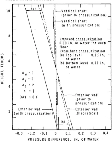
Fig. 6 illustrates the effects of combined pressurization and chimney action, with equal ex- cess a i r supply at all levels equivalent to an im- posed pressurization of 0.10 in. of water, which neutralizes the pressure difference across the ground floor entrance. The resultant pressuriza- tion i s somewhat greater than that imposed and in- creases from bottom to top because a non-linear flow relation i s assumed. F o r a flow exponent of one, the resultant pressurization would equal that
F i g . 6 E f f e c t of uniform i m p o s e d p r e s s u r i z a t i o n on s t a c k p r e s s u r e d i f f e r e n c e s V e r t i c a l s h a f t V e r t i c a l s h a f t
-
-
O A T = 0 F-
p r e s s u r i z a t ~ o n )-
E x t e r i o r w a l l - -0.3 -0.2 -0.1 0 0.1 0.2 0.3 0.4 P R E S S U R E D I F F E R E N C E , I N . O F WATERimposed. It will also be noted that the pressure difference a c r o s s the floors i s less when the build- ing i s pressurized uniformly. Because the flow relation i s non-linear there i s less upward flow through the building; for high values of imposed pressurization the ratio of actual to theoretical chimney draft approaches one. For linear flow conditions this ratio i s constant.
An equal excess of supply a i r on all floors, a s illustrated in Fig. 6, can be effective in reducing the p r e s s u r e difference across exterior walls a t lower levels, but there i s a penalty in increased p r e s s u r e differences which cause exfiltration a t higher levels. The total excess a i r supply, which must be provided by outside a i r , is equivalent to 29@& of the a i r infiltration with no pressurization for the conditions illustrated.
P r e s s u r e differences across ground floor en- trances can be neutralized by providing an excess air supply only on that floor. In the 10-story model this requires an imposed pressurization on the ground floor of 1.2 in. of water (Fig. 7). The pressure distribution across the exterior wall, floors and verticalshaft i s essentially the same as that illustrated in Fig. 5, in which pressure dif- ferences a c r o s s the entrance were neutralized by increasing the a r e a of the entrance opening, Aw, to about 8.
The excess a i r supply required in Fig. 7 i s approximately equivalent to the a i r infiltration through the enlarged entrance opening in Fig. 5. It must be supplied by the introduction of outside air through the ventilation system; the amount r e - quired i s about equal to the total a i r infiltration without pressurization. Infiltration on other floors below the neutral zone level i s about 37% of the original total infiltration. This infiltration, to- gether with the excess supply a i r required to neu- tralize the pressure difference across the entrance in Fig. 7, i s substantially l e s s than the total excess supply a i r required with uniform pressurization a t all levels. Consequently, the increase in pressure difference a c r o s s upper levels of the building i s much less than that in Fig. 6. With a greater r e - sistance to flow within the building the increase in p r e s s u r e difference at upper levels would be still less; with a lower resistance there would be a greater effect a t upper levels and a greater excess air supply required to neutralize the pressure dif- ference at the entrance.
To counteract pressure differences from chimney action a c r o s s exterior walls in the upper floors requires an excess of exhaust a i r over sup- ply. One approach, involving net supply below the neutral zone and net exhaust above, i s illustrated in Fig. 8, where the imposed pressurization i s 0 . 1 in. of water for all floors
-
positive below the neu- t r a l zone and negative above it. The resultant pressurization i s less than that when excess a i r supply at all levels i s uniform (Fig. 6), but i s equal and of opposite sign a t the top and bottom. P r e s s u r e differences a c r o s s the floors and verti- cal shafts a r e greater than with no pressurization. This arrangement has the advantage that p r e s s u r eE x t e r i o r w a l l V e r t i c a l s h a f t
- 0 . 2 - 0 . 1 0 0.1 0 . 2 " -0.10 0 0.1
P R E S S U R E D I F F E R E N C E , I N . O F W A T E R
Fig. 7 E f f e c t o f first floor pressurization t o neu- tralize entrance pressure d i f f e r e n c e
differences a c r o s s both top and bottom of the en- closure a r e reduced.
The second example in Fig. 8 i s for the 10- story model with vertical shafts split a t the mid- height, as in Fig. 4. With the same excess supply and exhaust in lowerand upper halves of the build- ing, as in the example above, a much greater p r e s s u r e difference occurs a c r o s s the floor a t mid-height. The result i s that pressure differ- ences across the enclosure a r e essentially bal- anced at top and bottom of the building, while there a r e substantial p r e s s u r e differences causing exfil- tration immediately below mid-height and infiltra- tion immediately above. The greater the increase in resistance to flow inside the building in relation to that of the exterior, the greater will be the p r e s s u r e difference a c r o s s the floors and vertical shafts and the resultant pressurization for a given excess of supply or exhaust air.
In theory it would be possible to neutralize the p r e s s u r e difference a c r o s s outside walls due to chimney action over the full height of the building by controlling excess supply o r exhaust in each story. This i s illustrated in Fig. 9 for the 10- story model. To maintain an average pressure difference of z e r o a c r o s s the walls of each story, the pressure difference a c r o s s each floor separa- tion must equal the theoretical draft from floor to