HAL Id: in2p3-00022021
http://hal.in2p3.fr/in2p3-00022021
Submitted on 27 Nov 2013
HAL is a multi-disciplinary open access
archive for the deposit and dissemination of
sci-entific research documents, whether they are
pub-lished or not. The documents may come from
teaching and research institutions in France or
abroad, or from public or private research centers.
L’archive ouverte pluridisciplinaire HAL, est
destinée au dépôt et à la diffusion de documents
scientifiques de niveau recherche, publiés ou non,
émanant des établissements d’enseignement et de
recherche français ou étrangers, des laboratoires
publics ou privés.
GANIL
M. Di Giacomo
To cite this version:
M. Di Giacomo. Design and manufacturing tools for RF resonators at GANIL. 15th International
Con-ference on Cyclotrons and their Applications, Jun 1998, Caen, France. pp.175-178. �in2p3-00022021�
DESIGN AND MANUFACTURING TOOLS
FOR RF RESONATORS AT GANIL.
M.DI GIACOMO,
Spiral group, Ganil, B.P. 5027, 14076 Caen Cedex 5
ABSTRACT Two new resonators have been designed and installed at Ganil during last years. Since design to manufacturing. several different phases have to be passed to achieve a tinal result respecting the required specifications. Each of these phases needs specific tools and procedures that have deeply profited of recent technological development. The article resumes how all that was applied at GANIL and the results obtained.
l. RF resonator design
During the design of resonant structures the RF engineers must always take into account the different aspects of the mechanical feasibility: thermal and vacuum deformations, required tolerances, alignment, movement in vacuum of
sliding elements, geometrical controls, etc. When sliding contacts are used, the maximum current density they can carry has to be taken in great care. All those aspects have to be considered especially during the final phase of
optimisation of the total volume and of the course of the tuning elements. All those aspects are as important as the RF calculations to obtain a reliable resonator.
1.1 RF Design Codes
Design of cyclotron cavities doesn't justify 3D electromagnetic codes and we still use a 2D method based on the classical transmission-line approximation. According to this method, the resonators is divided into a limited number of subsections of terminated loss less transmission lines, each one defined by two parameters: the characteristic impedance Zc and the length t.
The main code we use for the design of the resonators is RES.HF [I] which was initially developed by C. Bieth. It
has been adapted to the Macintosh platform and extended with additional graphical features and design functions like computation of inductive coupling and of trimmer effects. Poisson release 4[2] is intensively used, coupled to our program ZETA, to calculate values of capacitance of
geometrical figures.
CHA3D[3] is used were 2D approximation is not reliable, like in the odd geometry of central regions where the intensities of the tields determine the voltage the resonator will stand before sparking (Kilpatrick field).
1.2 The RES.HF program
The program RES.HF analyses the set of transmission line subsections (of characteristics impedance Zc and length t)
to tind /-,/4 or /-./2 resonant modes. Either the length of the tinal section or a sub-set of characteristic impedances can be unknown corresponding to a sliding short or a capacitive panel tuning system. All the resonator characteristic parameters, like the shunt impedance R, the Q factor, the stored energy Wand the voltage distribution along the gap are calcu lated.
The power densities on all the model surfaces are calculated for the maximum voltage required at each frequency. These data are essential for the design of the cooling system. Two types of trimmers can be treated: sliding panels situated in the high impedance part of the cavity or plungers located in the sliding short region. Their effect in terms of
total amount offrequency shift and the sensitivity (Khz/mm) are calculated.
Inductive coupling is automatically calculated either in the form of impedance of a given dimension loop or in the form of variable dimension of a loop that will match a 50 Ohm feeder line. The output levels of pick-up loops are also calculated.
All the parameters of a resonator scaled of a factor E are also given.
1.2.1 The trimmer model
Two solutions are possible to calculate the trimmer effects. The first one, which was used for the R2 panels, consists in specifying to the program the sections whose boundary is effected by the trimmer movement and the variation dZc corresponding to a I mm displacement of the trimmer surface. Then RES.HF calculates the frequency shift corresponding to the given set of dZc at the calculated resonator length.
Another solution comes from the Slater perturbation theorem [4] which gives the amount of frequency shift ;1f when a small volume ;1V is removed from the cavity by pushing the boundaries. [n those cases where you can consider that either the electric or the magnetic field is dominant, the Slater relation reduces to :
6fl f == 6W IW
I)
where W is the energy stored in the cavity. For plunger type trimmer located in the sliding short region the energy perturbation Dw can be approximated by the formula:
2)
and the tield in this region with a radial distribution:
I
H(r) = -"-. 3)
2n· I'
1.2.2 Coupling Model
The coupling coefficient kc/ (proportional to the mutual inductance) depends only on the geometrical characteristics of the loop.
M=&k 2n
,I
4)
On the other side the resonators parameters wO" Qo and
R,
and the required impedance Zo are related to the mutual inductance M by :セ@
M= '\j£.I)·1'., wl)·QI)
5)
The program calculates the loop dimensions giving the suitable k" coefficient.
1.3 The ZETA Program
Calcu lations of the characteristic impedance have been optimised taking advantage of the CAD features and of 2D electrostatics codes. Sections available from the CAD system are accurately described to the POISSON code in order to obtain the electrical field intensities on the electrode profile : file Tape28. Data of this file are fmally treated with our program ZETA to obtain the capacity (per unit length) and thus the characteristic impedance of the section.
The Zeta program is based on the Poisson relation giving the charge density s corresponding to the field intensity E :
(J'=EE,
The total charge q (per unit length) of the section is given by integration on the profile of the charge distribution Introducing the voltage V at which the field distribution was calculated, the capacity per unit length C is simply obtained by :
C=qN
as well as the characteristic impedance Z, (c being the velocity of the light) :
Z, =lkC
2. Mechanical design
During the design of resonant structures the RF engineers must always take into account the different aspects of the mechanical feasibility: thermal, weight and vacuum deformations, required tolerances, movement in vacuum of
s liding elements. External constraints as room limits are often added by the surroundings . Reference points for al ignment and the installation procedure have also to be
foreseen. /cf4 resonators at frequencies of some tenths of
MHz require in fact big and heavy structures that have to be precisely aligned to the rest of the machine and this operation is sometimes completely independent of the assembling of the cavity itself.
Several tricks concerning the vacuum criteria have to be
respected as well as the RF ones.
In the case of CIME, struct ural calculation s were necessalY to as sure the correct position of the cantilever electrode whose thickne ss was in contrast with the inel1ia required. The code used is ACORD[S] and severa l different fi'ames were studied. The final expected deformation is shown in figure 1.
r.1.1O r. 0.,5 r· 0.15
fibre ュッセ・ョョ・@ de La slruclure chargee, Bvanl r8glage
Figure I: electrode structure calculated arrow
Figure 2 shows the applied solution: the electrode frame is divided in three sections . Each one is mounted with a starting angle so that the three ending points stay again on the median plane, thus compensating the weight deformations.
Figure 2:. the cyclotron electrode structure 2.1 Thermal design
Another critical point is the cooling system design : powers of th e order of several kW per tenth of kY having to be dissipated . Cime resonators needs 48 KW to stand 100 kY. The design criterium to obtain homogeneous and weak deformations is to avoid that the temperature between two cooled points rises more than 10 degrees higher of the input temperature of the cooling water.
We use the ACORD code to calculate temperature distribution on the Cu surfaces. ACORD requires power density input data that are calculated by RES.HF.
of ' 1 I "O,s IS H セ@ 0 , 0 -\-1 W / _ _ t ·c T セ@ l"O 15 3(,·;; . 16 15 B ... c.. Ef"'O'S K: Sow iセᄋ」@ Nセエ⦅セ@
Figure 4: the sliding short cooling pipes
A proper cooling system extends the trimmer life time , shows a more stable load to the amplifier, simplifies regulation problems, as it reduces the period of the frequency shift and of the associated phase and amplitude oscillations. The water velocity in the pipes must be less than few meterl sec in order to avoid induced vibration. It's useful to install a cooling circuit all along the accelerating gap or those areas where multipactor or sparks are expected.
3. Manufacturing
Manufacturing of big resonators is always a very delicate phase. Very different technologies are involved : copper and stainless steel welding and machining, vacuum aspects, fine alignments , control. etc. Furthermore, each one is rather a prototype and sometimes, solutions which seems to be correct on the paper have to be modified during realisation. Thus, a continuous analysis of what is functional or not is needed and a deep transparency and collaboration with the manufacturer is indispensable.
As well for R2 as for C[ME the manufacturer was chosen on the base of his experience, his organisation and control possibilities. A partnership with an external organism assuring the mechanical control was defmed. Several meetings were spent ana lysing together all the most crucial points either on the RF and the mechanical sides. A quality procedure was defined identifying all the break points for technical controls all along the manufacturing and the assembling of the different elements . Particular importance was given to the control of the properties of the basic materials : OFHC cupper, セ\PLPR@ stainless steel; the quality of the cupper welding (high RF conductivity), and of the cupper surface rugosity (R <0.8) were frequently checked. Choice of welding procedures is also a key parameter. On the electrodes of R2 and C[ME, we have intensively used the Electron Beam (EB) solution . EB is interesting to prevent deformations due to important heating of large surfaces or to grant correct welding of parts which can be risen to high temperature only locally . The two valves of the inner lines of both resonators are welded EB. Pipes braised at low temperature are present in both cases very near to the welding interface and water is flowing in the pipes dur ing EB operation. Naturally , proper settings of the EB parameters (power and focusing of the beam) is required but the welding is possible with pipes as near as 10 or 12 mm. EB was a lso used to weld together the different parts of the electrode .
Figure 5: the cyclotron electrode
Cleaning procedures for the different materials are of primary importance for vacuum and to reduce difficulties in passing through the multipactor. Standard CERN procedure were used.
4. Results
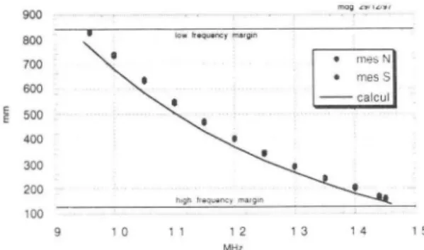
Final results on both resonators show excellent agreement between calculated and measured parameters . The frequency ranges are completely covered, the trimmer and the coupler systems fully correspond to the design criteria, the shunt impedances are less than ten percent weaker than expected. 2D RFC simulation is consequently perfectly reliable when carefully applied, proper manufacture of the scaled model being of greatest importance for that purpose.
900 800 700 600 500 400 300 200 100 mag セB G iLH G GG G@
Figure 6: Cyclotron resonator tuning positions
4800 4600
E
4400 >- 4200 0; <3 4000 3800 3600 9 1 0 11 1 2 1 3 14 MH zFigure 7: Mesured and calculated
Q
values (loaded) 15450 mdg 30/1'2197
•
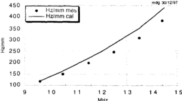
Hzirnrn イョ・セ@ 400 --Hzlmmcal•
350 E 300•
E N 250 I•
200•
150•
100 9 10 11 12 13 14 15 MHzFigure 8: Mesured and calculated trimmer sensibilities 4.1 Routine operation
On the other hand the behaviour of the two cavities about multipactor and breakdown voltages is completly different and doesn't fit our expectatives.
No multipactor problems at all and voltages much higher than expected have been observed (with or without magnetic field) on the CIME resonators, while very long conditioning periods, which have to be repeated after long stand-by-time, affect the R2 resonator.
Even if the vacuum pression is very good (few 10.7) we suspect the presence of a polluting agent inside the vacuum chamber, and we are going to investigate on it.
5. Conclusions
Measurements and operating results have confmned the validity of our designing tools and manufacturing procedures. Nevertheless we still have to discover the reasons of the problems affecting the rebuncher. There, RF design and manufacturing criteria are not sufficient and we still have to develop some tools to predict easy operation of high voltage resonators.
References
[I] C. Bieth, Le systeme accelijruteur de Canil
-78R1053/HF/02 -(1978)
[2] Los Alamos Laboratories , The PoissoniSuperjish codes
LA-UR-87-115 (1987)
[3] P. Bertrand, Recent Fortran 90 developments in 3D
electric jield calculation and application related to the SPIRAL project at Canil, CAP 96
[4] D.M.Pozar, Microwave Engineering, ed Addison-Wesley (1990)