Publisher’s version / Version de l'éditeur:
Journal of the Acoustical Society of America, 94, 5, pp. 2713-2720, 1993-11
READ THESE TERMS AND CONDITIONS CAREFULLY BEFORE USING THIS WEBSITE. https://nrc-publications.canada.ca/eng/copyright
Vous avez des questions? Nous pouvons vous aider. Pour communiquer directement avec un auteur, consultez la première page de la revue dans laquelle son article a été publié afin de trouver ses coordonnées. Si vous n’arrivez pas à les repérer, communiquez avec nous à PublicationsArchive-ArchivesPublications@nrc-cnrc.gc.ca.
Questions? Contact the NRC Publications Archive team at
PublicationsArchive-ArchivesPublications@nrc-cnrc.gc.ca. If you wish to email the authors directly, please see the first page of the publication for their contact information.
NRC Publications Archive
Archives des publications du CNRC
This publication could be one of several versions: author’s original, accepted manuscript or the publisher’s version. / La version de cette publication peut être l’une des suivantes : la version prépublication de l’auteur, la version acceptée du manuscrit ou la version de l’éditeur.
For the publisher’s version, please access the DOI link below./ Pour consulter la version de l’éditeur, utilisez le lien DOI ci-dessous.
https://doi.org/10.1121/1.407354
Access and use of this website and the material on it are subject to the Terms and Conditions set forth at
Sound transmission through slotted concrete blocks with attached
gypsum board
Warnock, A. C. C.
https://publications-cnrc.canada.ca/fra/droits
L’accès à ce site Web et l’utilisation de son contenu sont assujettis aux conditions présentées dans le site LISEZ CES CONDITIONS ATTENTIVEMENT AVANT D’UTILISER CE SITE WEB.
NRC Publications Record / Notice d'Archives des publications de CNRC:
https://nrc-publications.canada.ca/eng/view/object/?id=528698c9-c69e-4171-a934-faf996104c95 https://publications-cnrc.canada.ca/fra/voir/objet/?id=528698c9-c69e-4171-a934-faf996104c95Sound t ra nsm ission t hrough slot t e d c onc re t e bloc k s w it h a t t a c he d
gypsum boa rd
N R C C - 3 6 1 3 5
W a r n o c k , A . C . C .
N o v e m b e r 1 9 9 3
A version of this document is published in / Une version de ce document se trouve dans:
Journal of the Acoustical Society of America, 94, (5), pp. 2713-2720,
November-93
http://www.nrc-cnrc.gc.ca/irc
The material in this document is covered by the provisions of the Copyright Act, by Canadian laws, policies, regulations and international agreements. Such provisions serve to identify the information source and, in specific instances, to prohibit reproduction of materials without written permission. For more information visit http://laws.justice.gc.ca/en/showtdm/cs/C-42
Les renseignements dans ce document sont protégés par la Loi sur le droit d'auteur, par les lois, les politiques et les règlements du Canada et des accords internationaux. Ces dispositions permettent d'identifier la source de l'information et, dans certains cas, d'interdire la copie de documents sans permission écrite. Pour obtenir de plus amples renseignements : http://lois.justice.gc.ca/fr/showtdm/cs/C-42
Sound transmission through slotted concrete blocks with attached
gypsum board
A. C. C. Warnock
Acoustics Laboratory, Institute for Research in Construction, National Research Council, Ottawa, Ontario KIA OR6. Canada
(Received 12 August 1991; revised 14 June 1993; accepted 6 July 1993)
Measurements of sound transmission loss through slotted concrete blocks with attached gypsum board showed that the cavity resonance of the blocks has an important beneficial effect. It counteracts the mass-air-mass resonance that occurs when gypsum board is added to the surface of a concreie block wall leaving an air space behind it. This significantly increases the sound transmission class rating relative to the same systems with normal-weight nonslotted blocks. The effects of the two resonances could be seen at different frequencies when there was no sound-absorbing material in the air space behind the gypsum board. When the air space was filled with sound-absorbing material, however, both resonances moved together and could not be separated, but the transmission losses and sound transmission class for the composite wall were still significantly greater than those for wall systems using nonresonant blocks. Sound absorption measurements for the slotted blocks showed the need for one-third octave band data in place of the octave band data often found in trade literature.
PACS numbers: 43.55.Rg, 43.55.Ev
INTRODUCTION
Previous work presented sound transmission loss data
for normal weight1 and porous, lightweight2 block systems
with attached gypsum board. This previous work demon· strated the importance of the mass-air-mass resonance and the influence of sound-absorbing material and block poros-ity on this resonance. Specially constructed blocks with slots in their faces connecting to internal cavities show a Helmholtz resonance, generally at low frequencies. Such blocks absorb sound strongly around the cavity resonance.
Their properties have been discussed by Junger3 who refers
to earlier work by Westphal4 and Lindahl.5 Junger gives the following equations for predicting the resonance fre-quency fcav : f"v= ( l/21T) セkimL@ K=pc2A;toiV, (I) (2) (3)
where K =stiffness of air in the cavity, M =mass of air slug
in slot, V=volume of the cavity in the block (m3),
A,101=area of the slot opening (m 2
), £=length of the slot
(m), \ャᆪ]PNTセaL
QPQ
Mエィ・@ end correction for the slots,p=density of air, kg/m3, c=speed of sound, m/s.
Using electroacoustic analogs, Westphal predicted that an array of resonators on the surface of a wall would result in increased transmission loss at and around the resonance frequency. He presented transmission loss data for a honeycomb partition formed from 3.5-mm-thick sheets of material with and without 5-mm holes in one face. Predictions and measurements agreed well. On the basis of this and Lindahl's measurements, Junger suggests that slotted concrete blocks should also give an improved transmission loss around the resonance frequency relative
to normal blocks. The data from Lindahl and Westphal showed improved transmission loss at frequencies higher than the resonance; this is not predicted by Westphal's simple model.
Other workers have looked at the effects of Helmholtz resonators in double-panel cavities. The impetus for some of the work comes from the interest in attenuating propel-ler noise passing through the fuselage of aircraft. 6 Enger
and Vigran7 presented data for double-pane windows
where there were Helmholtz resonators around the edge of the cavity. As well, they added some sound-absorbing ma-terial around the reveals. At the conference where the data were shown, an electroacoustical analog of the
double-panel wall with an enclosed resonator was presented. 8
Ma-son and Fahy" presented a more detailed model and narrow-band measurements that were in general agreement with their model. Both models predict the same kind of behavior; the Helmholtz 'resonance decreases sound trans-mission around the resonance frequency. This increase in sound insulation can counteract the increase in sound transmission due to the mass-air-mass resonance. The Ma-son and Fahy model predicts that the improvement in sound insulation depends on the ratio of the volume of the resonators to the volume of the cavity of the double wall. The electroacoustical analog contains no such dependence. In both cases the added resonators were placed around the periphery of the cavity.
The purpose of the work presented in this paper was to find how the Helmholtz cavity resonance in slotted con-crete blocks interacts with the mass-air-mass resonance that arises when gypsum board is added to the surface of concrete blocks leaving an air space behind it. In this type of construction, the gypsum board is fairly close to the
resonator slot and may alter the resonance in some way. It
is also common to add sound-absorbing material in double-2713 J. Acoust. Soc. Am. 94 (5), November 1993 0001·4966/93/94(5)/2713/8/$6.00 2713
Front View
Horizontal Section
T
2 40140
1'----FIG. l. Dimensions of slotted acoustical blocks used in the measure-ments.
wall cavities to increase the sound insulation. The presence of the sound-absorbing material might also have an effect on the Helmholtz resonance.
Three possibilities existed: (I) The two resonances would remain independent of each other and the improve-ment due to the Helmholtz resonance would counteract the detrimental effects of the mass-air-mass resonance. (2) The addition of gypsum board in front of the slots in the block face might destroy the Helmholtz resonance, because of the proximity of the gypsum board to the slots. The cavity inside the block might then contribute to the total volume behind the gypsum board and lower the mass-air-mass resonance. (3) There might be some interaction where both resonances are strongly influenced, for example shifted in frequency, with no obvious benefits or disadvan-tages.
To investigate these possibilities, a wall was built from slotted, acoustical blocks. The paper that follows presents the data for the bare wall, the wall with gypsum board added to one or both faces with and without sound-absorbing material in the cavity.
I. MATERIALS
The slotted blocks used for these measurements were 140-mm thick and each weighed 14.6 kg. The dimensions of the block are shown in Fig. 1. tィセ@ surface weight of the completed wall was 197 kg/m2• The flow resistivity of the block material was 1. 7 X 10⁵ mks rayl/m. Alternate blocks faced in opposite directions so slots were exposed on both faces of the wall. It is essential when the wall is constructed in this way that a full mortar bed is used. If this is not done, sound easily passes through the slots on one face, through the gaps in the mortar and out through the slots on the other face. The sound insulation of a wall built with such errors would be very low.
2714 J. Acous1. Soc. Am., Vol. 94, No.5, November 1993
(a) > - - 4 o - - - < (b)
QSiセ@
6 5 - - - - l
>--so-FIG. 2. Cross sections of the furring and studs used to support gypsum board. (a) 13-mm resilient metal channels, (b) 40-mm steel studs.
Gypsum board with a thickness of 12.7 mm and weighing 8.8 kg/m2 was attached to the block wall using 13-mm resilient metal channels and 40-mm steel studs. The stud systems had top and bottom tracks and were not in contact with the blocks. This resulted in the distance from
the gypsum board to the block surface being about 5 to 10
mm larger than the stud depth. Channels and studs were formed from 0.5-mm-thick galvanized sheet metal and were installed 600-mm apart. Figure 2 shows cross sections and dimensions of the channels and studs.
When sound-absorbing materials were installed in the air space between the gypsum board and the blocks, two types were used. With 13-mm resilient metal channels, a 25-mm-thick blanket of low-density glass fiber weighing 0.3 kg/m2 was installed. (Because of the low density, the compression was deemed unimportant.) With 40-mm steel studs, a 38-mm-thick blanket of mineral fiber weighing 2.3 kg/m2 was installed.
II. MEASUREMENT FACILITIES AND PROCEDURES
Measurements were made in the sound transmission loss suite at the National Research Council Canada in
ac-cordance with ASTM E90. 1
°
For wall transmission lossmeasurements, the source room has a volume of 65 m3 and
the receiving room has a volume of 250 m3• Wall speci-mens measure 2.44 X 3.05 m and are constructed on a steel, wheeled frame lined with wood. The frame fits between the rooms and is isolated from both. Each room has fixed and rotating diffusers and four comer-mounted loudspeaker systems fed from independent, pseudorandom noise
sources. To measure transmission loss, whlte noise is fed to
the loudspeakers in the source room. Pink noise is used to measure decays in the receiving room. Condenser micro-phones sample the sound fields at nine positions in the central volume of each room. Measurements are controlled by a computer system interfaced to a Norwegian Electron-ics type 830 real-time analyzer and cover the one-third octave band frequencies from 63 to 6300 Hz.
Ill. SOUND ABSORPTION MEASUREMENTS
Sound absorption for the blocks was measured
accord-ing to ASTM C423.11 Room reverberation times were
mea-sured with no specimen in the room-the empty room condition. They were then measured with the blocks in-stalled. The blocks were laid on the floor of the reverber-ation room )Vith 13-mm-thick pieces of plywood between A. C. C. Warnock: Walls of slotted blocks and gypsum board 2714
!z
w (3 u:: u.. 1.2l!j
0.8 () z Q 0.6 セ@ a:r4
0.2•
"..
'' ' ':
ZᄋセN@On floor, all slots up
I \
セᄋセLセZZZ@
..
125 250 500 1k 2k
FREQUENCY (Hz)
FIG. 3. Sound absorption coefficients for 140·mm slotted blocks in three configurations: On the floor with all slots exposed; on the floor with half of the blocks facing up; in wall opening with half of the slots exposed. The solid dots are the coefficients given in the manufacturers' literature.
them to simulate mortar. A frame of the same plywood surrounded the array of blocks. Joints between the frame and the blocks and between adjacent blocks were covered with fabric-backed tape. This was done to eliminate sound absorption due to the crevices at these locations. Without this tape, measurements showed increased sound absorp-tion. There is no standard procedure for preparing con-crete blocks for sound absorption measurements, but the installation just described is typical laboratory practice. The blocks were tested once with all slots facing upwards and once with alternate blocks facing down so only half of the slotted faces were exposed.
Sound absorption was also measured with the blocks mortared together as a wall in the transmission loss open-ing. It was not practical to replace the wall with a highly reflecting surface, so, to get the "empty" room case, the slots were sealed with 3-mm-thick, 25-mm-wide polysulfide glazing tape. The flaw in this procedure is that the absorp-tion due to the block material is eliminated from the mea-surement; this biases the measurement. To compensate for this, the wall absorption coefficients are increased by 0.17 at all frequencies for plotting in Fig. 3. This somewhat arbitrary increase was adopted to give reasonable agree-ment between the floor and wall measureagree-ments at frequen-cies around 500 Hz.
The three absorption spectra together with the manu-facturer's data are shown in Fig. 3. Some features of these data should be noted. Almost all of the data from the present work are lower than those given by the manufac-turer. Without more information, it is not possible to say exactly why this is so. The manufacturer's data are for blocks manufactured and tested in the USA. The blocks used in the present work were manufactured in Canada. There may be differences in materials. The manufacturer's data are for one-third octave bands one octave apart. From these data, one might have thought that the block reso-nance was at 250 Hz. One-third octave band data allow a 2715 J. Acoust. Soc. Am., Vol. 94, No. 5, November 1993
iii' !!. 60 セ@ 50
g
z 0 40 c;; UJ セ@ UJ 30 z <(セ@
20All slots closed STC 52
\
, ... ....··\ ,.···;:<·\Slots closed on one side
'-'•' .. ...- STC 50 '-_ .. ...- ""All slots open
STC48
63 125 250 500 1k 2k 4k FREQUENCY (Hz)
FIG. 4. Sound transmission losses for bare 140·mm slotted blocks. Re-sults with aU slots exposed, all sealed and sealed on one side only.
more precise estimate of the position of the resonance fre-quency, which in this case is 160Hz. Using the dimensions given in Fig. I and Eqs. (1). (2), and (3) gives a calcu-lated resonance at 175 Hz. The measured resonance is in fair agreement with this prediction.
With the ad hoc addition of the constant 0.17 to all coefficients to compensate for the block absorption, the absorption coefficients measured for the blocks tested as a mortared wall agree fairly well with those measured for the blocks on the laboratory floor with half the slots exposed. The peak in the absorption is less sharp for the blocks lying on the floor because the resonance seems to lie between two one-third octave bands. This is not a serious difference and probably arises because the plywood separators did not seal the cavities in the same way as the mortar did.
IV. SOUND TRANSMISSION LOSS FOR BARE BLOCKS Sound transmission through the bare wall was mea-sured for three conditions: (I) All slots sealed with 3-mm-thick glazing tape; ( 2) all slots on both sides open; and ( 3) the slots on one side only sealed with glazing tape. The glazing tape would not alter the wall stiffness but would remove the effect of the cavity resonance. The transmission loss results are shown in Fig. 4.
The figure shows that transmission loss is reduced at frequencies below about 250 Hz when the slots are ex-posed. Sound enters the cavity in the blocks and then passes through the block material to the receiving room. In Ref. 2, a relationship between STC and the flow resistivity of the block material was given. The value of flow resistiv-ity for the concrete in the present blocks shows that sig-nificant transmission through the block material is to be expected. Thus, for these unpainted blocks the slots do not increase transmission loss.
The data presented by Lindahl show the opposite effect-slotted blocks provide higher transmission loss val-ues than the normal blocks he tested. But, as he points out, the slotted blocks he tested were heavier than normal A. C. C. Warnock: Walls of slotted blocks and gypsum board 2715
iii' E 70
12
60g
z Q 5012
::E (/) 40:;;
a: ... 3075% solid normal blocks STC47
Lindah I slotted blocks STC49
セs・。ャ・、@
slotted blocks '·...
·
STC 52 RPセMlセセllセllセセセᄋセiMllセlセlw@ 63 125 250 500 1k 2k 4k FREQUENCY (Hz)FIG. 5. Sound transmission losses for slotted blocks and 75% solid nor-mal blocks.
blocks of the same size and same aggregate. Lindahl does not give the weight of the blocks he tested and his data apply to blocks that were sealed on one face. So while his data show better transmission losses for the slotted blocks, it is not conclusive that this was due to the cavity
reso-nance.
Figure 5 shows transmission loss for the slotted blocks used in the present work, for 75% solid, 140-mm-thick blocks from Ref. I and for the slotted blocks used by Lin-dahl. His data have been converted into modem one-third octave band format. The 75% solid blocks weighed 17.8 kg per block. Lindahl's data has the same general shape at low frequencies as the data for the sealed slotted blocks and the 75% solid blocks. There is no obvious feature in these three curves that can be attributed to the action of the resonant cavity. The dips in the curves around 250Hz are attributed to a structural resonance in the wall, the fre-quency of which is determined by the stiffness of wall and its dimensions. The peaks just below these dips appear for blocks without slots and are apparently not associated with the cavity resonance of the blocks.
Thus, in contrast to the results obtained by Westphal, these data suggest that the cavity resonance does not in-crease block wall transmission loss. Westphal's result, while unequivocal, was for a much lighter structure with a cavity resonance at 700 Hz. It is instructive to look at the electroacoustic model used by Junger and Westphal to see what improvement can be expected for block walls. This model is shown in Fig. 6. The values of m2 , C2 , and R2 are given by the following equations which are a rearrange-ment of those given by Junger.
2716 J. Acoust. Soc. Am., Vol. 94, No.5, November 1993
(4)
(5) (6) (7)
FIG. 6. Electroacoustic analog of concrete block wall with cavities on one face. The inductor m2 represents the mass of the air associated with the slots,
c
2 represents the compliance of the cavities, R2 represents the loss in the cavity, Z0 is the impedance of the air, and m1 represents the massof the blocks. The incident sound signal is represented by a generator with amplitude 2p0 .
where Q=the Q factor for the cavity resonance, !J.f =the width of the resonance at half the peak height, R=the ratio of total wall area to the total area of the slots.
According to the model in Fig. 6, the maximum im-provement in transmission loss arises at the cavity
reso-nance frequency given by Eq. (I). The absorption peak in
Fig. 3 has a Qofroughly 1.7. Using these relationships and simple circuit theory, it may be shown that the calculated improvement in transmission loss for these slotted blocks at the cavity resonance is only about 1.5 dB, which is rather small.
The superior performance of the slotted blocks seen in Fig. 5 and in Lindahl's work may be due to changes in wall stiffness or some other factor. The block wall used here was not painted and there was apparently significant transmis-sion through the concrete at the rear of the cavities. To clarify the effects of the cavities, measurements should be made on a slotted block wall sealed on the slotted side. Transmission loss measurements with the slots open and sealed with heavy glazing tape as done here would give a clear picture of the effects of the cavity resonance of the blocks.
V. SOUND TRANSMISSION LOSS FOR BLOCKS WITH ADDED GYPSUM BOARD
The transmission loss data for all the systems tested are given in Table I. Figure 7 shows transmission loss re-sults obtained when 13-mm gypsum board was attached to the wall on 13-mm resilient channels. The STC ratings obtained are several points higher than those obtained in Ref. I for normal 190-mm blocks.12 This is entirely due to the improved low-frequency performance. The peak in the transmission loss curves around 160Hz is undoubtedly due to the cavity resonance of the blocks.
Figure 8 gives results for the gypsum board supported on 40-mm steel studs with the space between the studs unfilled. Again, the STC ratings are higher than those ob-tained for comparable systems in Ref. I
.'3
TABLE I. Sound transmission losses for 140-mm slotted blocks with different surface finishes. The codes used in columns side 1 and side 2 have the
ヲッャャッキゥセァ@ meaning: Gl3-13-mm gypsum board; RC13-13-mm resilient metal channels; SS40--40-mm steel, studs; GFB or MFB-glass or mineral fiber biltts (the number following gives the thickness in mm).
Test Side 1 Side 2 STC 63 80 100 125 160 200 250 315 400 500 630 800 1000 1250 1600 2000 2500 3150 4000 5000 6300 39 G13-RC13 G13-RC13 57 26 19 20 37 49 50 47 40 Bare G13-RC13 55 29 23 24 33 41 43 44 47 Gl3-GFB13 G13-RC13 58 27 23 24 34 44 51 51 -RC13 50 G13-GFB13 G13-GFB13 58 27 24 26 33 39 47 53 -RC13 -RC13 51 G13-SS40 013-8840 60 19 20 26 38 50 48 44 53 G13-SS40 Bare 57 28 22 25 35 42 41 42 54 Bare Bare 49 32 24 26 28 30 34 39 78 Gl3-MFB40 G13-MFB40 64 23 25 32 40 50 56 56 -8840 -8840 79 G 13-MFB40 Bare 59 29 27 30 35 41 49 50 -8840
Figure 9 is for 40-mm steel studs with the spaces be-tween the studs filled with mineral fiber. There is no obvi-ous peak around 160 Hz and the STC ratings are the same as those obtained for similar walls in Ref. 1.14
In each case, a pattern similar to that in Ref. I is seen-at some low frequency, the curve for the bare blocks crosses the curves for the cases with gypsum board added. When both sides are finished, detrimental resonances get deeper and transmission loss improvements increase. When the air space behind the gypsum board is not filled with sound-absorbing material, the cavity resonance of the blocks is quite evident.
To see more clearly the effects of different air spaces, the addition of sound-absorbing material and the behavior of the Helmholtz resonance, the data are presented now as plots of A TL. A TL is the change in transmission loss, rel-ative to the bare block, that is associated with a given arrangement of gypsum board and support. It is assumed that each time a given gypsum board system is applied to the blocks, it has the same relative effect no matter what is
80
セWP@
eng
60 z 0 50 iii en セ@ 40 en z セ@ 30 1-20 Both sides STC57 1 side only STC 55 ' .. ···· .. ···...
---:::<·· .. ··'""
:' • .. ...-· Bare Blocks / . ...- STC49Adding resilient metal channels and drywall
Qッllセセセセセセセセ⦅lセセ⦅オ@
63 125 250 500 1k 2k 4k
FREQUENCY (Hz)
FIG. 7. Sound transmission losses for 140-mm slotted blocks with 13-mm gypsum board added on 13-mm resilient metal channels. The air space between the gypsum board and the blocks was empty.
2717 J. Acoust. Soc. Am., Vol. 94, No. 5, November 1993
46 48 56 63 69 73 76 76 76 76 72 74 78 76 45 46 51 57 61 66 69 69 68 68 64 65 70 72 53 55 61 65 69 74 76 76 76 75 72 74 80 81 60 62 64 68 71 75 76 77 78 77 74 77 80 77 48 57 63 67 69 73 77 78 76 76 75 74 71 66 46 52 58 61 63 67 71 74 74 72 69 72 77 77 43 44 47 49 51 55 58 59 59 59 55 56 61 64 61 61 61 63 65 69 76 78 77 73 71 74 80 78 54 54 56 59 61 65 70 72 72 69 67 71 77 80
on the other side of the wall. Thus, in Fig. 7 for 13-mm gypsum board and resilient metal channels, one estimate of A TL is obtained by subtracting the transmission losses for the bare block from those for the block with 13-mm gyp-sum board and resilient metal channels on one side. An-other estimate is obtained by subtracting the bare block data from the result for the gypsum board and channels on both sides. This gives 2ATL, so the result is divided by 2. These two estimates are averaged to get a mean ATL. Other procedures followed for finding the mean A TL are explained in Ref. I.
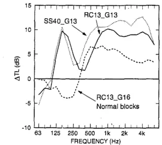
Figure 10 shows the average ATL when there was no sound-absorbing material in the air space behind the gyp-sum board. It also shows for comparison, a result for nor-mal blocks from Ref. 1. In Ref. I, the crossover frequency
f
x was defined as . the frequency where the A TL curvecrosses the zero axis. It is usually about 1.8 times higher than the calculated mass-air-mass resonance frequency. The effect of the cavity resonance of the blocks is clear; it counteracts the detrimental effects of the mass-air-mass
80 20 2 sides, STC 60 LNセセ@
.
.
ャZセZWZセ^@
:····:.·' Bare blocks .' .... . ...- STC49 40 mm steel studs and drywall 63 125 250 500 1k 2k 4k FREQUENCY (Hz)FIG. 8. Sound transmission losses for 140-mm slotted blocks with 13-mm gypsum board added on 40-mm steel studs. The air space between the
gypsum board and the blocks was empty.
80 CD "'-70
セ@
...J 60 z Q gJ 50 セ@ U}セ@
40 2 sides, stセ@ ,./....
セMNN@.
/ '•,/ 1 side, STC 59 / __ /___"
··· .....
--
.... /. , _.. ,.·· ... Bare blocks / ' ... ...- STC49 30 MセMM ... ·· RPセセセセNNNjwセセセセセセセ@ 63 125 250 500 1k 2k 4k FREQUENCY (Hz)FIG. 9. Sound transmission losses for 140 mm using slotted blocks with 13-mm gypsum board added on 40-mm steel studs. The air space between the gypsum board and the blocks was filled with mineral fiber.
resonance and prevents the negative ATL seen for the nor-mal blocks around this frequency. The system transmission loss is greatly improved at low frequencies relative to the case of blocks without resonant cavities although there are still negative ATL values below 100Hz. The benefits of the air space are still obtained above the crossover frequency. If the block cavity acted only to increase the volume of the air space behind the gypsum board, the additional vol-ume would correspond to an increase in air space of about
14 mm. The corresponding shifts calculated for the
mass-air-mass resonance and the crossover frequency fx are
rather small. If the rising parts of the curves in Fig. 10 around 250 to 500 Hz are extended back to the zero A TL axis, this gives estimated crossover frequencies of about
10 5 CD
"'-RC13_G13\-
.... セ@...
j:!<I 0
1-=--o:--..
'i/-
.. - - - ! - - - 1
-5 ' ., ··\ ____ /"'RC13_G16 Normal blocks -1 0 セQNNMGZNZGZMGMセNNNjwZZMGMZMlMlNャNNMGMNNwNNNNjwMLlMjNNNNw@ 63 125 250 500 1k 2k 4k FREQUENCY (Hz)FIG. 10. AVerage change in transmission loss セtl@ for air spaces con-taining no sound-absorbing material. A result for a normal block is in-cluded for comparison. The symbols identify the gypsum board and the method used to support it as follows: 8840=40-mm steel studs; RC13 =resilient metal channels; 013= 13-mm gypsum board; 016= 16-mm gypsum board.
2718 J. Acoust. Soc. Am., Vol. 94, No.5, November 1993
10 -5 SS40_G13
"
:.'-·
' i.. /-..._ RC13_G16 Normal blocksCavities filled with fibrous absorber ", ,.· / ·· .. -1 0 uNNャMlセNNljMGMBMB」」GMGMGMjNNNlセNNNlNjwNNNw@ 63 125 250 500 1k 2k 4k FREQUENCY (Hz)
FIG. 11. Average -change in transmission loss, .6.TL, for the air space behind the gypsum board filled with sound-absorbing material. A result for a normal block is included for comparison. The symbols identify the gypsum board and the method used to support it as follows: SS40 =40-mm steel studs; RC13=resilient metal channels; Gl3= 13-mm gyp-sum board; 016=16-mm gypgyp-sum board.
250 and 315 Hz. Crossover frequencies can also be calcu-lated using1•2
fx= 108/ セmL、L@ (8)
where Md is the surface mass of the gypsum board, kg/m2,
and d is the depth in meters of the air space behind it. For the 40-mm studs and the 13-mm channels, the calculated values are 170 and 315 Hz which are in fair agreement with those above. Thus, the data show that when the cavity is not filled with sound-absorbing material, the two reso-nances do not interact and remain at the frequencies given by the equations above.
The work done in Ref. I showed that adding sound-absorbing material to the air space behind the gypsum board lowered the mass-air-mass resonance and the cross-over frequency. Figure II shows what happens in the case of these slotted blocks. The frequency of the Helmholtz resonance moved to 200 Hz, although the resonance is not prominent in the case of the 13-mm air gap. This shift can be explained by saying that the sound-absorbing material acts to reduce the effective length of the slots in the block; the AL correction is zero. 15 This gives a change in fre-quency of the correct size. The less prominent resonance for the 13-mm air gap can be explained by saying that the
Q of the Helmholtz resonance has been reduced by the
sound-absorbing material, although it is not obvious why this should be so in one case and not the other. The low-ered mass-air-mass resonance makes it impossible to sepa-rate the two resonances in the graph. Comparison of the A TL curve for normal blocks with the other two curves shows that for both the 13- and 40-mm air spaces there are still substantial benefits obtained at low frequencies due to the action of the Helmholtz resonance; the crossover fre-quency is lower than the 160 Hz observed for the normal blocks. The shift in crossover frequency cannot be ex-plained by postulating that the volume of the space behind A. C. C. Warnock: Walls of slotted blocks and gypsum board 2718
FIG. 12. Electroacoustic analog of slotted cavity block wall with added gypsum board. The inductor m2 represents the mass associated with the
slots, C2 represents the compliance of the cavities, R2 represents the loss
in the cavity, Z0 is the impedance of the air, and m1 represents the mass
of the blocks. C3 represents the stiffness of the air space behind the
gyp-sum board which has mass m3 . The incident sound is represented by a generator with amplitude 2p0 .
the gypsum board is increased by the volume of the block cavity. This indicates that there are still two resonances active.
Calculations using a modification to the electroacous-tic analog given above show that the behavior seen here for the empty air space is to be expected. Figure 12 shows the modified model. C3 represents the stiffness of the air space
behind the gypsum board which has mass m3 kg/m2• C3 is
given by d! pc2
• Using this model, the improvement in
transmission loss relative to mass law predictions for m1
can be calculated.
Calculations were made for air space depths of 13 and 40 mm. The results are compared in Figs. 13 and 14 with measured ATL data. The general shape of the calculated ATL curves at low frequencies is similar to those mea-sured. Calculated results are sensitive to the value of Q
used for the cavity resonance of the blocks. When the value
30 20 -calculated 10 ··· .... ···. ·· .. iii'
···"'-:!;!. ..J Measured'<i
0 ·10 ·20 LLL..l....L.L...W....W-1-.L..l....L.L--"-:'-'-'-:J....w...l 63 125 250 500 1k 2k 4k FREQUENCY (Hz)FIG. 13. Measured and predicted .6.TL for 13-mm air space behind gyp-sum board.
2719 J. Acoust. Soc. Am .• Vol. 94, No.5. November 1993
30 20 10 iii' :!;!. ..J
'<i
0...
···"···
.•.• -z:···
/ Measured ·1 0 ·20 LLJ....J....L.L...W....L..L...l...J....J....L.L...W....l....L...l...w..J 63 125 250 500 1k 2k 4k FREQUENCY (Hz)FIG. 14. Measured and predicted .6.TL for 40-mm air space behind gyp-sum board.
of 1. 7 estimated from absorption measurements was used,
the two resonances were not セA・。イャケ@ seen. To show them more clearly, a Q of 6 was used in the calculations.
Even this crude model confirms that the cavity reso-nance of the blocks has a much greater effect on transmis-sion loss when the cavities are behind the gypsum board than when they are exposed to the sound field. The model also predicts low frequency resonances in the 80- and 100-Hz bands for the 13- and 40-mm air spaces, respec-tively. These are due to a mass-air-mass resonance where the cavity compliance is determined approximately by the sum of
c2
andc3'
that is the volume of the cavity in the blocks adds to the volume behind the gypsum board. The data show negative ATL there which may be due to such resonances. As shown in Ref. 2, the depth of the mass-air-mass resonance can be reduced by the action of block po-rosity. The airll.ow resistivity of the concrete in that case was 1.3 X 10⁵ mks rayl/m. In this case, the airll.ow resistiv-ity was 1. 7 X 10⁵ mks rayl/m so one can expect similar reductions of the depth of the mass-air-mass resonance. The data in Fig. 4 also show that there was transmission through the pores of the block material; the model does not simulate this transmission.The model predicts that ATL will increase at 12 dB/ octave at frequencies much higher than the mass-air-mass resonance. This is because the model has no element to simulate line and edge connections between the gypsum board and the blocks. Line, edge, or point connections existed in the real wall and would account for the plateau in the t>TL curves at high frequencies.
Attempts to use these simple, electroacoustic analogs to simulate the effect of adding sound-absorbing material to the air space behind the gypsum board gave results that were in no way similar to those measured. These models are of limited usefulness.
VI. DISCUSSION
The absorption measurements suggest that several re-finements to the test procedures are needed to deal with
slotted concrete blocks. Since they are strongly resonant absorbers, absorption coefficients should be measured at least in one-third octave bands; the one-third octave band data at octave band frequencies found in manufacturers' literature can be quite misleading. Differences between specimens measured on the floor of the laboratory and those measured in a wall opening could arise due to inad-equate simulation of the mortar between the blocks. A standard installation practice to be used when measuring the absorption of concrete blocks is needed.
The sound transmission loss measurements showed that the Helmholtz resonance associated with the slotted blocks acts independently of the mass-air-mass resonance associated with the gypsum board and the air space behind it. This fact could be used to design walls with high STC ratings and minimum thickness.
Adding sound-absorbing material to the air space be-hind the gypsum board changes the behavior of the mass-air-mass resonance and the Helmholtz resonance. In this case, when the sound-absorbing material was added, both resonances moved together and could not be seen as
sepa-rate.
This paper has presented more examples of the inter-action between gypsum board and concrete block walls. As in the previous two papers, questions are raised that appear to be unanswered in the literature. The systems presented here might be impractical because of cost but there may well be benefits for building acoustics if inexpensive reso-nant systems can be developed.
1 A. C. C. Warnock, "Sound transmission through concrete blocks with
2720 J. Acoust. Soc. Am., Vol. 94, No. 5, November 1993
attached drywall," J. Acoust. Soc. Am. 90, 1454-1463 (1991).
2 A. C. C. Warnock, "Sound transmission through two kinds of porous
concrete blocks with attached drywall," J. Acoust. Soc. Am. 92,
1452-1460 (1992).
3M. C.
Junger, "Helmholtz Resonators in Load-Bearing Walls," Noise Control Eng. 4 I, 17 (1975).
4Wolfgang Westphal, "Beeinfiussung der Schalldammung von Wanden
durch Resonateren," Proceedings of 4th International Congress on Acoustics, paper M36, August, 1962.
s Robert Lindahl, "Sound Transmission Loss Characteristics of a Hollow Concrete Block with a Slotted Face," Proceedings of 6th International Congress on Acoustics, paper eセSセVL@ p. B-101, August, 1968.
6H. L. Kuntz, R. J. Gatineau, and R. A. Prydz, "Acoustic Transmission
Loss Flight Test Results for an Aircraft Cabin Enclosure," Inter-Noise 89, 211 ( 1989).
71. Enger and T. E. Vigran, "Transmission Loss of Double Partitions containing Resonant Absorbers," Proc. Inst. Acoust. 7, part 2, 125 (1985).
8T. E. Vigran (personal communication).
9 J. M. Mason and F. J. Fahy, "The Use of Acoustically Tuned
Resona-tors to Improve the Sound Transmission Loss of Double-panel Parti-tions," J. Sound Vib. 124(2), 367 (1988).
10 ASTM E90, "StatJdard Test Method for Laboratory Measurement of Airborne Sound Transmission Loss of Building Partitions.''
11 ASTM C423, "Standard Method for Sound Absorption and Sound
Ab-sorption Coefficients by the Reverberation Room Method."
12190-mm-thick normal-weight blocks with 16-mm drywall and 13-mm
resilient metal channels on one side gave STC 51. With drywall and channels both sides, an STC of 49 was obtained.
13190-mm nonnal-weight blocks with 16-mm drywall mounted on 50-mm
resi1ient metal Z bars on one side gave and STC of 52. With the same treatment on both sides, the STC was also 52.
14 A nonnal-weight 190-mm concrete block with 50-mm resilient metal Z
bars, sound-absorbing material and 16-mm drywall on one side gave an STC of 59. With the same treatment on both sides, the STC was 64.
15The author is indebted to the reviewer who suggested this explanation.