HAL Id: hal-01792917
https://hal.archives-ouvertes.fr/hal-01792917
Submitted on 16 May 2018
HAL is a multi-disciplinary open access
archive for the deposit and dissemination of
sci-entific research documents, whether they are
pub-lished or not. The documents may come from
teaching and research institutions in France or
abroad, or from public or private research centers.
L’archive ouverte pluridisciplinaire HAL, est
destinée au dépôt et à la diffusion de documents
scientifiques de niveau recherche, publiés ou non,
émanant des établissements d’enseignement et de
recherche français ou étrangers, des laboratoires
publics ou privés.
Heat transfer intensification and flow rate control in
dynamic micro-heat exchanger
P. Kumar, Charles Gonzalez, François Pigache, Pascal Lavieille, Frédéric
Topin, Marc Miscevic
To cite this version:
P. Kumar, Charles Gonzalez, François Pigache, Pascal Lavieille, Frédéric Topin, et al.. Heat transfer
intensification and flow rate control in dynamic micro-heat exchanger. 13th International Conference
on Heat Transfer, Fluid Mechanics and Thermodynamics (HEFAT2017), Jul 2017, Portorož, Slovenia.
�hal-01792917�
HEAT TRANSFER INTENSIFICATION AND FLOW RATE CONTROL IN DYNAMIC
MICRO-HEAT EXCHANGER
P. Kumar2, J. Fontaine1, C. Gonzales1, F. Pigache1, P. Lavieille1, F. Topin2, M. Miscevic1* *Author for correspondence
1LAPLACE, CNRS UMR 5213, Université de Toulouse, 118, Route de Narbonne 31062 Toulouse Cedex 9, France
2IUSTI, CNRS UMR 7343, Aix-Marseille Université, 5, Rue Enrico Fermi, 13453 Marseille Cedex 13, France
E-mail: [email protected]
ABSTRACT
Technological advancements to improve flow and heat transfer characteristics in many processes are of great interest. Many high performance systems demand simultaneously the compactness, efficiency and control of heat transfer. In this view, a new concept of micro heat exchanger was proposed for the cooling of electronics devices for which the quality of heat exchange between wall and fluid as well as pumping effect are very critical. In the present work, the ability of a liquid heat exchanger involving a dynamic deformation of one of its walls to cool a microprocessor is investigated. For that purpose, 3-D numerical simulations were performed using commercial software based on the finite volume element in transient regime. Effect of geometrical and actuation parameters has been explored and the ability of such heat exchanger to simultaneously pump the fluid and enhance the heat transfer has been demonstrated. Based on these numerical results, a physical prototype has been designed and realized. First experimental results on the pumping capacity of this prototype have been compared with numerical results. The good agreement obtained allows validating the numerical procedure and thus to be confident in the numerical parametric study presented.
INTRODUCTION
The temperature control and associated heat flux management is crucial in many applications: microelectronics, embedded or fixed power electronics systems, power station, air conditioners, heat pumps, as well as in the field of industrial thermal processes metallurgy, chemistry, food, etc. The will to increase the performance and efficiency of these systems greatly amplifies this need, as in many situations it becomes the limiting factor in the optimization of the system performance. Moreover, lifetime and reliability of many systems are very strongly related to the quality of the thermal management.
It is nowadays common to meet chemical or thermal systems whose channels have sub-millimeter hydraulic diameters. This trend towards miniaturization is mainly due to the increasing demands of new and effective mixing or heat transfer technologies for various industrial fields, associated to the increasing need to control highly exothermic or explosive chemical reactions [1-2].
NOMENCLATURE
𝐴! [−] Relative amplitude
𝐶! [J/kgK] Specific thermal capacity
𝐷! [m] Hydraulic diameter
𝑓! [Hz] Frequency
𝑔 [m] Minimum gap of the channel
ℎ [W/m!K] Mean heat transfer coefficient at the heated wall
ℎ [W/m!K] Global heat transfer coefficient at the heated wall
𝑘! [W/mK] Fluid conductivity
𝐿 [kg/s] Imprint length of heated zone
𝑚 [m] Mass flow rate
𝑞 [W/m!] Heat Flux
𝑃! [Pa] Pressure gain in actuated zone
𝛥𝑃 [Pa] Pressure difference between outlet-inlet sections
𝑃! [W] Pumping power
𝑝 [m] Perimeter of the channel passage
𝑆 [m!] Exchange surface
𝑡 [s] Time
𝑇!" [K] Mean fluid temperature at a given axial position
𝑇!" [K] Mean fluid temperature in the channel
𝑇! [K] Mean wall temperature on a heated zone
𝑇! [K] Mean wall temperature in the actuated zone
𝑢 [m/s] Average velocity
𝑊 [m] Channel width
𝑊! [W] Imposed power
Special characters
𝛿 [m] Average distance between walls
𝜌 [kg/m!] Fluid density
𝜆 [m] Wavelength
𝜔 [/m] Number of waves per unit length
𝜇 [kg/ms] Dynamic viscosity Relative
𝜏 [s] Period
Heat transfer and pressure drop in sinusoidal corrugated channels have been studied by Nishimura et al. [3]. These authors showed that transition between laminar and turbulent flows is obtained at lower Reynolds number (Re = 300) compared to straight channel due to unsteady vortex motion. Similarly to the case of flat channel, the friction factor is inversely proportional to Reynolds number in the laminar flow range, while it is independent of Reynolds number in the turbulent range. Extending this study, Nishimura et al. [4] studied flow patterns characteristics in symmetrical two-dimensional sinusoidal and arc-shaped corrugated channels at moderate Reynolds numbers (20 ≤ 𝑅𝑒 ≤ 300). They concluded that the transitional Reynolds number depends on the corrugation shape. For instance, transition from laminar to
turbulent flow occurred at lower Reynolds number for the arc-shaped wall as compared with the sinusoidal wall. Niceno and Nobile [5] have conducted an extended numerical study on these corrugated channels. The results indicate that these two corrugation shapes are ineffective in terms of heat transfer rate (slightly higher for sinusoidal channel compare to arc-shaped channel) as compared to flat channel in steady low Reynolds flow. The unsteady regimes appear at different Reynolds numbers for the two corrugation shapes: unsteady regime was
observed at Re = 60-80 for arc-shaped channel and at Re =
175-200 for sinusoidal channel. On the other hand, heat transfer rate increases significantly for both corrugation shapes, up to a factor of three, as a result of self-sustained oscillations. Moreover, this transfer rate was found to be higher for arc-shaped channel while the friction factor was smaller for sinusoidal channel.
Naphon [6] conducted a numerical study on various corrugation geometries arranged in in-phase and out-phase layouts (e.g. flat plate, arc-shaped, trapezoidal and V-shaped) to enhance the thermal performance. He obtained that for a given air flow rate, V-shaped corrugated channel has the most significant effect on the enhancement of the heat transfer.
So, corrugated channels lead to enhance the heat transfer by disturbing the boundary layer. Most of the studies revealed an increase in overall thermal performance from 3 to 5 times depending on the working fluid. However, static corrugated channels have shown to increase significantly the pressure drop. In such corrugated (and grooved) mini-channels, high heat transfer usually leads to high Reynolds number (mostly turbulent) flow.
On the other hand, Léal et al. [7] proposed a very simplistic model of dynamic corrugated mini-channel to be operated at low Reynolds number. This has been achieved by deforming dynamically one of the channel walls. Very high heat transfer has been obtained compared to static corrugated channel. It appeared to be the first study to introduce dynamic wall in such mini-channels heat exchanger.
Very recently, Kumar et al., [8] extended this works and proposed a realistic 3-D geometry of dynamic corrugated heat exchanger. In their work, the average height of the channel is fixed while the minimum gap (distance between the lowest point of the deformed wall and the fixed wall) varies as a function of the relative amplitude. Numerical studies have been conducted by imposing high pressure and low pressure at the outlet and inlet sections of the channel, respectively, for an imposed frequency of 50Hz. It was observed heat transfer coefficient increases with increase in amplitude and the requirement of external pump could be completely eliminated due to self-pumping capacity of the device.
A first attempt to realize a physical prototype based on this principle has been made by Miscevic et al. [9]. The heat exchanger developed had close (but different) dimensions than the ones considered in the numerical study of Léal et al. [7]. In this prototype, one of the walls constituting the channel was subjected to dynamic deformations in the form of a traveling wave. Electric heaters on the other wall were heating the channel. Actuation was achieved by means of 10 piezoelectric actuators with homemade mechanical amplification systems.
Experimentally, the pumping function and the heat transfer intensification were shown. Nevertheless, the performances were less than expected mainly because the membrane was not rigid enough and induced unwanted deformations.
In partnership with a number of industrial partners, a liquid heat exchanger involving a dynamic deformation of one of its walls was realized [10]. The aim of this paper is to determine the ability of this latter liquid heat exchanger to cool a micro-electronic device. Both physical and virtual prototypes have been designed and realized, and parametric numerical simulations have been performed. The designed micro-heat exchanger uses three actuators to deform dynamically one of its walls. A systematic numerical study was conducted on a simplified geometry to understand the impact of operating parameters in enhancing thermo-hydraulic characteristics. Then, the first experimental results obtained with the physical prototype are used to validate the numerical procedure that has been applied to the same geometric system (using CAD of prototype and actuators command).
NUMERICAL PROTOTYPE
In the studied configuration, the lower wall was fixed and subjected to a constant heat flux along the imprint of heating zone while the dynamically deformed upper wall (also called “membrane” in the following) and side walls i.e. inlet and outlet sections were kept adiabatic. Three piezoelectric actuators were employed to dynamically deform the upper wall of a rectangular cross section micro-channel in order to simultaneously enhance heat transfer and pump the fluid.
Figure 1. Cross-section of dynamically corrugated micro-channel. The lower wall is subjected to constant heat flux between 𝑥! and 𝑥! (sections 𝑆! and 𝑆!), the gap g is the minimum height of the channel. Upper profiles are drawn for 2 different amplitudes and same gap (see orange and blue colored channels for clear distinction).
The length of the actuated zone (𝐿 = 𝑥!− 𝑥!) is 45.7 mm
while width (𝑊) is 50 mm. The channel gap (𝑔) is fixed and is 10µm while the average height of the channel (δ) is linked to the wave amplitude employed for wall deformation and the channel gap.
The lengths of input and outlet zones have been chosen long enough to establish the hydrodynamic. Furthermore, the no-slip condition was imposed on the walls.
The influences of relative amplitude (𝐴!), frequency (𝑓!)
and wavelength (𝜆) on thermo-hydraulic performances are
x
y
z
studied for an imposed value of the pressure difference between outlet and inlet of the exchanger equal to zero.
Only three actuators were employed in the present study. The channel cross-section shape is presented in Figure 1 where the actuator positions can be described using 𝑥! and 𝑥!, 𝑥! and 𝑥!
and 𝑥! and 𝑥!. The positions 𝑥! and 𝑥! are fixed to external inlet and outlet zones as dampers. These small zones make the fluid to enter and leave in laminar condition. The micro-channel geometry is composed of four main parts: inlet zone, heated surface where the heat power is imposed, outlet zone and membrane. Sidewall damping has been imposed on the lateral side of the actuated zone: along main flow axis, the membrane displacement is linearly interpolated between actuators and fixed zone.
3-D numerical simulations were carried out using the commercial software StarCCM+. This software allows modeling fluid flow and heat transfer in dynamically deformed structures. The flow was considered transient, three-dimensional and laminar. The working fluid was liquid water (properties taken from IAPWS-97 at 27°C) whose all thermo-physical properties were supposed constant for systematic studies. The imposed heat power (𝑊!) on the imprint (heated
zone) was 65W (note that only half of the device is modeled due to symmetry).
The results presented focus on the “active zone” namely between 𝑆! and 𝑆! sections (see Figure 1). All representative
global thermo-hydraulic quantities were calculated in this zone.
GOVERNING EQUATIONS
The incompressible laminar and transient conjugate flow and heat transfer problems were solved. The classical combination of continuity, momentum and energy equations are as follow, considering constant physical properties of the fluid: 𝛻 ∙ 𝑢 = 0, (1) 𝜌𝜕𝑢 𝜕𝑡 + 𝜌 𝑢 ∙ 𝛻 𝑢 = 𝜌𝑔 − 𝛻 ∙ 𝑃 + 𝜇𝛥𝑢 (2) 𝜌𝐶! 𝜕𝑇 𝜕𝑡+ 𝑢 ∙ 𝛻𝑇 + 𝜌𝑢 ∙ 𝜕𝑢 𝜕𝑡+ 𝜌 2 𝛻 𝑢 ! ∙ 𝑢 = 𝑘!𝛥𝑇 + 𝜕𝑃 𝜕𝑡 (3)
where, 𝑢 is the velocity vector, 𝑃 is the pressure, 𝑇 is the temperature, 𝑔 is the gravity acceleration, 𝜌 is the density, 𝜇 is the dynamic viscosity, 𝐶! is the specific thermal capacity and
𝑘! is the thermal conductivity of fluid, respectively.
The numerical resolution used a segregated approach with implicit second order temporal discretization and ad hoc relaxations factors in order to obtain adequate convergence behavior. The displacement of the top membrane is created by:
(1)- fixing the vertical position of the membrane in inlet and outlet zones at chosen height δ (average height of channel),
(2)- adding the movement of the three actuators (Eq. 4), (3)- in between two actuators or one actuator and border, the displacement is simply interpolated.
The displacement of actuator is given by the following equation for i=1,2,3 corresponding to actuator along main flow axis: 𝐴𝑐𝑡! 𝑥, 𝑡 = 𝐴!. 𝑐𝑜𝑠 2𝜋𝑓!𝑡 + 𝛷! (4)
where 𝛷!=0°, 𝛷!, 𝛷! are phase of actuators 𝐴𝑐𝑡!, 𝐴𝑐𝑡! and 𝐴𝑐𝑡!, respectively.
3-D NUMERICAL SIMULATIONS
In the studied configuration, the vertical plane passing through the central axis of the channel is a plane of symmetry, so only half of the channel was simulated (i.e. W/2=25mm). The imposed power on the modeled half-imprint was thus 32.5W to carry out numerical simulations (see Figures 1 and 2). This allows us to reduce the number of mesh cells to optimize computation time by dividing the simulated configuration by two compared to its actual size. Note that the fluid flow was considered in x −direction while the width and height of the channel were considered in y − and z−directions respectively.
Figure 2. Mesh view micro-channel at an arbitrary time.
Dimension in the z-direction is magnified 50 times. The bottom wall is uniformly heated below the actuated zone (fine mesh), all other walls are kept adiabatic.
Meshing strategy was similar to the one used by Kumar et al. [8]. It was rather tricky to create a convenient mesh in such highly anisotropic geometrical configuration subjected to large amplitude deformations (up to 98 % of channel height) while keeping a computational time low enough to carry out parametric study without sacrificing precision or convergence of the dynamic transfer.
The deformed channel mesh is presented in Figure 2 in case of an actuator size of 11mm and a phase-shift between two consecutive actuators of 120° (𝛷=0°, -120°, -240°).
DATA REDUCTION
In case of dynamic corrugated channel, surface averaged and volume averaged thermo-hydraulic quantities for all operating configurations were calculated as follow.
The Reynolds number and hydraulic diameter are defined by: 𝑅𝑒 =𝜌 𝑢 𝐷! 𝜇 , 𝐷!= 1 𝜆 4𝑆 𝑝 𝑑𝜆 ! ! (7) Where 𝑆 is the flow fluid passage area along the heated zone and p is the perimeter of the passage section, respectively. Note that these quantities are averaged over a time period.
The local heat transfer coefficient is obtained by the spatial and temporal averaged fluid temperature and wall temperature over the width and on a period (𝜏 = 1/𝑓!):
𝑇! 𝑥 = 1 𝜏𝑊 𝑇! 𝑥, 𝑦, 𝑡 𝑑𝑦 !!! !!! 𝑑𝑡 !!! ! (8)
𝑇!" 𝑥 = 1 𝜏𝛿𝑊 𝑇!"(𝑥, 𝑦, 𝑧, 𝑡)𝑑𝑦 !!! !!! 𝑑𝑧 !!! !,! !!! 𝑑𝑡 !!! ! (9) The local heat transfer coefficient and Nusselt number are then defined as:
ℎ 𝑥 = 𝑞 𝑥
𝑇! 𝑥 − 𝑇!" 𝑥
, 𝑁𝑢 𝑥 =ℎ 𝑥 𝐷!
𝑘! (10)
In the following, the global heat transfer coefficient and Nusselt number across the channel are then defined as:
ℎ = 𝛤
𝑆 𝑇! − 𝑇!"
, 𝑁𝑢 = ℎ 𝐷!
𝑘! (11)
Where ∗ denotes volume and surface averages for both
fluid and wall between sections 𝑆! and 𝑆!.
MESH CONVERGENCE
The calculations to test mesh convergence were performed
for amplitude (𝐴!) =85µm and frequency (𝑓!) =20Hz.
Mesh size
We initialized both corrugated shape and fluid flow. Then, calculations were carried out until a periodic stationary regime is reached. This latter point is checked comparing the temporal evolutions of global heat transfer and flow characteristics: calculations were performed until the heat transfer coefficient values between two consecutive time periods differs by less than 1 %. Consequently, an additional time period is added to extract all instantaneous and time-averaged values of all physical quantities.
Table 1. Presentation of global thermal and flow properties for different mesh sizes (for number of time step per period TS=50).
BMS 𝑚 (𝑔𝑠) 𝑇! (K) 𝑇!" (K) ℎ (W/m2K) 𝑇!" (K) 𝑇!" (K) 3 mm 1.11 312.51 307.87 13829 301.1 313.8 2 mm 1.10 312.51 307.85 13765 301.1 313.8
From the Table 1, it can be seen that reducing the mesh size from 3 to 2 mm does not impact strongly on the global properties. The % differences between the properties are respectively: 0.14% for 𝑚, 0.0024% for 𝑇!, 0.006% for 𝑇!",
0.47% for ℎ , 0.0095% for 𝑇!! and 0.0095% for 𝑇!". On increasing the mesh size, the properties vary significantly while reducing it further do not lead to any additional improvement. Based on these observations and the % difference in the properties, we chose the BMS (Base Mesh Size) =2mm to perform the systematic studies.
Time step requirement
To perform the numerical simulations in terms of time effectiveness as well as the precision, it is very important to obtain an optimized time step (TS). We test the following number of time steps per period: 20, 50, 75 and 100. Based on these time steps, global characteristics have been presented in Table 2. It can be observed that heat transfer coefficient values
decreases with increase in TS. On the other hand, Δ𝑇!= 𝑇!−
𝑇!" increases with increase in TS.
Table 2. Presentation of global thermal and flow properties for different time steps (for BMS=2mm)
TS (-) 𝑚 ( 𝑔 𝑠) (K) 𝑇! 𝑇(K) !" ℎ (W/m2K) 𝑇!" (K) 𝑇!" (K) 20 1.14 311.7 307.3 14610 300.9 312.6 50 1.10 312.5 307.9 13765 301.1 313.8 75 1.10 312.7 308.0 13615 301.2 314.1 100 1.06 312.8 308.0 13384 301.2 314.2
In order to obtain an optimized TS value, we have calculated the percentage variation of ℎ and Δ𝑇! for different
time steps based on the lowest value as a reference value for both these quantities. When TS=50, we observed variation of
ℎ equal to 2.84% while variation in 𝛥𝑇! (%) is 6.14%. The
global results of different characteristics do not vary strongly when increasing TS. Moreover, higher value of TS increases the computational time while the properties vary within a difference of 3%. Hence, TS=50 has been chosen to study the impact of different amplitudes and frequencies. The procedure has already been compared to another numerical study in Schmidmayer et al. [11]; influence of fluid properties has also been studied in this paper. The results obtained let us confident in the numerical approach.
LOCAL RESULTS
Figure 3. Instantaneous velocity field: for 𝐴!=100µm and
𝑓!=10Hz. Color range (Blue : 0 - Red 1 m/s). The vertical scale
is magnified 100 times. Channel height is 10 µm below center actuator and total length is 7 cm.
Local fields are presented for the dynamic heat exchanger with 𝐴! = 100 µm and 𝑓!= 10 Hz for an arbitrary time during
periodic stationary regime. During the expansion of the dynamic channel, the fluid moves in the longitudinal direction because of the successive expansions and contractions. Wall movement induces vertical (i.e. towards heated wall) displacement of the fluid. Characteristic times associated to vertical and horizontal fluid displacement are similar and significantly lower than the actuation one.
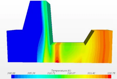
Due to the movement of the channel wall, cold fluid is moved near the heated wall successively at every location; this boundary layer disruption increases sharply heat transfer along with mixing that takes place within the core flow. On temperature field, successive hot and cold “plumes” could be seen (fig. 4).
Near the inlet, the cold fluid fills the pocket during expansion, then, it is driven towards the heated surface, and eventually
transferred below the next actuated zone. The constricted zone
acts as a barrier separating inlet and outlet parts. This leads the fluid to fill the expansion zone while being mixed efficiently; it is then transferred in the next pocket over time. These “bursts” repeat cyclically along with mixing thus increasing heat transfer.
Figure 4. Instantaneous temperature field for 𝐴!=100µm and
𝑓!=10Hz. Vertical scale is magnified 100 times. Cold fluid fill
the space below 1st actuator (here ascending) with small backflow due to the 2d actuator “pressing” the fluid on surface (height is about 50µm). The fluid is mainly driven toward 3rd
actuator and outlet.
Qualitatively, thermal and hydraulic fields dynamics remain similar for all tested conditions although some differences in terms of phase-shift or amplitude are observed on temporal
variations of temperature, pressure and velocities. Thus,
changes in the thermo-hydraulic performances with operating parameters are expected to guide optimal design of the physical prototype.
GLOBAL RESULTS
The global thermo-hydraulic characteristics of the proposed configuration of dynamically morphed heat exchanger are presented in the following figures and tables.
Frequency and Amplitude impact on flow rate
Mass flow rate is proportional to both frequency and amplitude. High frequency leads to fast movement of the corrugated wall, which in turn enhances the mass flow. The latter is therefore directly proportional to the frequency (Figure 5.a). Increasing amplitude (at constant gap) leads to increase the channel volume thus to have more fluid in the channel. This behavior also enhances mass flow rate in the system, which is also directly proportional to the amplitude (Figure 5.b). Note that increasing amplitude at constant gap adds mainly volume to the channel near the membrane and increases average height.
Figure 5. Influence of (top) Frequency for 𝐴!=100µm and,
(bottom) Amplitude for 𝑓!=10Hz on mass flow rate.
Figure 6. Influence of (top) Frequency for 𝐴!=100µm and,
(bottom) Amplitude for 𝑓!=10Hz on heat transfer coefficient.
0 0.5 1 1.5 2 2.5 3 3.5 0 10 20 30 40 50 ma ss flo w ra te ( g/ s) Frequency (Hz) 0 0.1 0.2 0.3 0.4 0.5 0.6 0.7 0.8 0.9 1 50 60 70 80 90 100 ma ss flo w ra te ( g/ s) Amplitude (µm) 10000 11000 12000 13000 14000 15000 16000 17000 0 10 20 30 40 50 He at tr ansf er c oe f. (W/m 2K) Frequency (Hz) 10000 10500 11000 11500 12000 12500 13000 13500 14000 14500 50 60 70 80 90 100 He at tr ansf er c oe f. (W/m 2K) Amplitude (µm)
Frequency and amplitude impact on heat transfer
Heat transfer coefficient also depends on both frequency and amplitude imposed. Increasing frequency increases the mixing effect and the fluid velocity. Thus it results in high heat transfer coefficients varying roughly proportionally to the frequency (see Figure 6a).
On the other hand, increasing amplitude -while keeping the gap (minimum height below actuators) constant- leads to increase the average height of the channel and thus reduces the heat transfer coefficient. This one is thus found to decrease linearly with the amplitude (see Figure 6b). Nevertheless, the heat transfer coefficient remains very high (>10 000 W/m2K)
for all tested cases.
Influence of gap on thermo hydraulic performance
Influence of gap size has been tested on mass flow rate and heat transfer for amplitude 100µ𝑚 and frequency 10 𝐻𝑧. The initial gap was fixed at 10µm. The gap size varied from 10µm up to 35µm. In figure 7, it can be easily observed that the mass flow rate decreases with increasing gap and, as expected, the heat transfer coefficient decreases with increasing channel height. This is due to two main effects: the average fluid thickness increases, and the fluid velocities decrease.
Figure 7. Influence of gap size on (top) mass flow rate and
(bottom) heat transfer coefficient for 𝐴!=100µm and 𝑓!=10Hz.
Mainly, the most constricted zones become less and less efficient as the gap increases. As these zones (which cross all
the channel length) are the locations where the most efficient heat transfer takes place, it is not surprising to observe a net decrease in heat transfer coefficient.
Two main conclusions could be drawn from these results: although the heat transfer coefficient decreases when increasing channel height for sub-millimeter cases, it remains high enough to produce a very small thermal resistance compared to the others involved in a chip cooling assembly (e.g. contact resistances etc.). As the flow increases with the channel height, the need to remove relatively high power with limited inlet-outlet temperature difference will be a more important design parameter. Moreover, required pumping power, mechanical efforts and constraints will be more easily met for the channel with « large » dimensions i.e. going more towards 1 millimeter than 100 µm.
Using these trends along with mechanical power consumption and pressure variations constraints have allowed us to design a physical prototype of self-pumping high performance actuated heat exchanger.
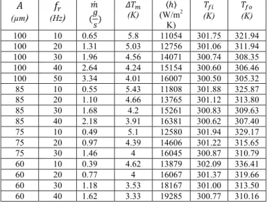
Table 3. Presentation of operating parameters (wave amplitude and frequency) on mass flow rate, difference of surface and mean fluid temperatures, heat transfer coefficient, inlet-outlet fluid temperatures,.
𝐴 (µm) 𝑓! (Hz) 𝑚 (𝑔𝑠) 𝛥𝑇! (K) ℎ (W/m2 K) 𝑇!" (K) 𝑇!" (K) 100 10 0.65 5.8 11054 301.75 321.94 100 20 1.31 5.03 12756 301.06 311.94 100 30 1.96 4.56 14071 300.74 308.35 100 40 2.64 4.24 15154 300.60 306.46 100 50 3.34 4.01 16007 300.50 305.32 85 10 0.55 5.43 11808 301.88 325.87 85 20 1.10 4.66 13765 301.12 313.80 85 30 1.68 4.2 15261 300.83 309.63 85 40 2.18 3.91 16381 300.62 307.40 75 10 0.49 5.1 12580 301.94 329.17 75 20 0.97 4.39 14606 301.22 315.65 75 30 1.46 4 16045 300.87 310.79 60 10 0.39 4.62 13879 302.09 336.41 60 20 0.77 4 16067 301.37 319.66 60 30 1.18 3.53 18167 301.00 313.50 60 40 1.62 3.33 19285 300.77 310.16 EXPERIMENTAL PROTOTYPE
Due to the need of easy control of the frequency, large displacement (>100µm) and traveling wave like, the membrane deformation has to be obtained from forced actuation. A box containing 3 actuators that are fixed on top cover has been realized (fig.8 left).
Rectangular pads are fixed at the bottom of the actuators and glued to a membrane of suitable mechanical properties. The assembly cover-actuators-pads-membrane is then fixed on the top box (mechanical support, and fluid tightness) and placed above the sole of the heat exchanger. Two grooves are machined in the sole and communicate with the inlet and outlet pipes (fig. 8 right).
The actuator assembly is machined so that at rest, each pad pushes the membrane in contact with the sole. The membrane dynamic deformation is driven by the individual electric supply
0.57 0.58 0.59 0.60 0.61 0.62 0.63 0.64 0.65 0.66 0.67 0 5 10 15 20 25 30 35 40 ma ss flo w ra te ( g/ s) Gap size (µm) 10400 10600 10800 11000 11200 0 10 20 30 40 He at tr ansf er c oe f. (W/m 2K) Gap size (µm)
of each actuator – V-(t) is of the same kind that is described in
equation 4 – and for the maximum supply voltage the distance between the sole and the membrane is 200 µm (according to the datasheet of actuators, membrane properties and preliminary tests).
Figure 8. –Left: View of the top box containing the 3 actuators
(cover removed). The membrane is glued on the bottom of the actuators. –Right: View of the heat exchanger bottom wall, made of copper. The two grooves constitute the manifolds. Figure 9 shows the configuration of the hydraulic system: adjusting the vertical position of the two constant level tanks imposes the pressure at the inlet and the outlet of the channel. These heights are adjustable and may be changed as required for a given experiment. The mass flow rate is measured thanks to a precision balance, with an uncertainty less than 1% for all experiments. The pump P2 is used to fill the loop prior to each experiment.
Figure 9. Sketch of the setup: the test section is placed between
two constant level reservoirs that are open to the atmosphere and whose vertical positions can be adjusted.
RESULTS AND COMPARISON
To date, the experimental setup only allows characterizing the mass flow rate as a function of characteristics of the supply voltage of the actuators (type of signal, amplitude, phase-shift…). Only cold tests (i.e. without thermal solicitations nor measurements) have yet been carried out.
Tested configuration
Specific experiments have been done to determine the flow rate dependence to the phase-shift between actuators (imposed
with an uncertainty less than 1°) in case of a sinusoidal variation of voltage of frequency 10 Hz (+/- 0.1 Hz). Simultaneously, the virtual prototype geometry has been modified in order to comply with the experimental one (using CAD modelling) and numerical calculations were carried out with the same operating conditions considering peak-to-peak amplitude of 200 µm. The displacement of membrane is taken from the electrical command of the actuators (wave shape, frequency, phase-shift) associated with the exact pad geometry (length, width and spacing).
An additional damping function is used to take into account the relative width of channel and pads and progressively reduce the displacement from pad border to lateral position where the membrane is clamped. In the simulations, the actuator displacement according to time is sinusoidal and phase-shift between actuators 1&2 and 2&3 are equal. The peak-to-peak amplitude is fixed to a constant value of 200 µm. The gap g between the sole of the heat exchanger and the lower position of the membrane is set to 10 µm.
Figure 10. Comparison between experimental and numerical
time averaged mass flow rates as a function of the phase-shift between two successive actuators. The supply voltage of the actuators is sinusoidal with a frequency of 10Hz. The peak-to-peak amplitude and the gap are set to 200µm and 10µm, respectively.
Phase-shift impact on flow rate
Both experimental and numerical results are reported in figure 10 in terms of time averaged flow rate (over a span of multiple times during the actuation period). Both curves exhibit a slightly asymmetric bell shape. As expected, the flow rate is zero for phase shifts of 0 and 180 degrees.
Experimentally, a maximum flow rate of 1.8 g/s is reached for a phase-shift of 60°, while numerically it is 1.70 g/s, obtained with a phase-shift of 55°.
As it can be seen from this figure, and considering the uncertainties on experiments (especially on the real actuator displacement), the agreement between numerical and experimental results is excellent (5% difference). It can thus be concluded that the numerical procedure developed is reliable and could be used for device optimization and parametric exploration. Yet the thermal behavior remains to be validated.
0.0 0.2 0.4 0.6 0.8 1.0 1.2 1.4 1.6 1.8 2.0 0 20 40 60 80 100 120 140 160 180 Ma ss flo w ra te (g /s ) Phase shiF (°) Experiment simula:on
Title Pumping and thermal performance characterization of
prototype gen 1
Version v1.0
Page 15/25
CONFIDENTIAL
Figure 18 – Test bench for Canopée pumping performances
The test bench has been improved during the experimental campaign (replacement of weighting machine by Coriolis mass-flowmeter, replacement of flexible tubes by rigid fluid circuit …). However the main characteristics of the circuit are identical.
Several parameters are able to influence the flow rate and they are listed in the table below:
Parameters name Unit
Voltage waveform trapezoidal/sine/triangle
Voltage amplitude Min to Max voltage amplitude V
!"#$ V
!"%& V
frequency Frequency of voltage waveform Hz
Φ() Phase shift between actuator 1 and 2 degree
Φ(* Phase shift between actuator 1 and 3 degree
The actuators are supplied by independent voltage sources able to adopt different waveforms as illustrated on Figure 19.
prototype ∆P
Inlet
valve Outlet valve
Three-way valve Precision balance P1 P2 Constant level tank Constant level tank Imposed height difference Valve (offset of the pressure sensor) Valve
Title Pumping and thermal performance characterization of
prototype gen 1
Version v1.0
Page 15/25
CONFIDENTIAL
Ce document et les informations qu'il contient sont la propriété des sociétés citées. Ils ne peuvent être reproduits, communiqués, utilisés sans autorisation écrite préalable. This document and any data included are the property of named companies. They cannot be reproduced, disclosed or utilized without the company's prior written approval.
Figure 18 – Test bench for Canopée pumping performances
The test bench has been improved during the experimental campaign (replacement of weighting machine by Coriolis mass-flowmeter, replacement of flexible tubes by rigid fluid circuit …). However the main characteristics of the circuit are identical.
Several parameters are able to influence the flow rate and they are listed in the table below:
Parameters name Unit
Voltage waveform trapezoidal/sine/triangle
Voltage amplitude Min to Max voltage amplitude V
!"#$ V
!"%& V
frequency Frequency of voltage waveform Hz
Φ() Phase shift between actuator 1 and 2 degree
Φ(* Phase shift between actuator 1 and 3 degree
The actuators are supplied by independent voltage sources able to adopt different waveforms as illustrated on Figure 19.
prototype ∆P
Inlet
valve Outlet valve
Three-way valve Precision balance P1 P2 Constant level tank Constant level tank Imposed height difference Valve (offset of the pressure sensor) Valve
Temporal variations of flow rate
Figure 11 shows the instantaneous inlet and outlet flow rate for 2 phase-shifts between actuators. On the top graph –case a- this phase-shift is 120 °, thus the total volume of the channel stays constant. On the bottom graph –case b- the phase shift is 55° and it corresponds to the maximum average flow rate. For both cases, the flow rate varies periodically with time as expected, reverse flow is observed and extreme values of flow rate are largely superior (in norm) to the average one.
For case a, inlet and outlet flow rates are in phase (volume conservation) while in case b there is a time shift induced by the volume variation of the channel. In both cases, the maximum direct flow rate is largely superior to the reverse one. The ratio between the fluctuation amplitude and the average value depends directly on the actuator phase-shift.
The maximum (respectively minimum) flow rate is about 10 (respectively 3) times the average value for case a, and slightly less than 4 (respectively 2) in case b. Moreover, for case a, the flow rate variations are sinusoidal when it becomes less regular for other cases according to the actuators phase-shift.
For case a, with a phase-shift of 120° the total volume of the channel is constant over time, thus the outlet and inlet mass flow rates are identical at each instant. On the other hand, for case b the 55° phase-shift between actuators leads to temporal volume variations of the channel and thus creates a phase-shift between flow rate at the channel’s extremities.
Figure 11. Numerical instantaneous inlet and outlet mass flow
rates: (case a - Top) 120° phase-shift and (case b – Bottom) 55° phase-shift (Frequency 10Hz, peak-to-peak amplitude 200µm, gap 10µm).
This behavior depends on actuator phase-shift and actual dynamic displacement. Parametric influences will be the subject of future research work and used for thermo-hydraulic optimization of dynamic micro-channels.
CONCLUSION
Integration of the pumping function within a heat exchanger can be obtained considering dynamic morphing of at least one of the wall of the proposed heat exchanger. In addition, this dynamic morphing may conduct a significant heat transfer enhancement, making the concept particularly interesting for embedded thermal management systems.
A numerical tool has been developed that allows determining the thermo-hydraulic performances of such a heat exchanger. To meet the application constrains, the dynamic deformation has to be realized with a small number of actuators. So, only 3 actuated zones are considered in the present work. It has then been established that:
§ The mass flow rate is mainly controlled by the frequency and amplitude of the travelling wave, as well as the gap g and the phase-shift between two successive actuated zone; § High heat transfer coefficient values can be obtained, up to
16000 W/m2K;
The numerical results have been validated comparing the numerical mass flow rates with the ones obtained with a physical prototype. The agreement between the experimental and numerical results is excellent; the numerical procedure appears thus reliable.
ACKNOWLEDGEMENT
This work has been realized in the framework of the CANOPEE project and supported by the ”Fond Unique In- terministériel (FUI) - 18th call for projects”. We gratefully acknowledge contributions from all project partners.
REFERENCES
[1] Kandlikar, S.G., Heat transfer, pressure Drop and flow patterns during flow boiling in parallel channel compact heat exchangers of small hydraulic diameters, Heat Transfer Engineering, Vol. 23, No. 5, 2001, pp. 5-23.
[2] Kandlikar, S.G., Fundamental issues related to flow boiling in minichannels and microchannels, Proceedings of the 5th World Conference on Experimental Heat Transfer, Fluid Mechanics, and Thermodynamics, Thessaloniki, Greece, Vol. 1, 2001, pp. 129-146. [3] Nishimura, T., Ohori, Y., and Kawamura, Y., Flow characteristics
in a channel with symmetric wavy wall for steady flow, Journal of Chemical Engineering of Japan, Vol., 17, No. 5, 1984, pp. 466-471. [4] Nishimura, T., Murakami, S., Arakawa, S., and Kawamura, Y.,
Flow observations and mass transfer characteristics in symmetrical wavy-walled channels at moderate Reynolds numbers for steady flow, International Journal of Heat and Mass Transfer, Vol. 33, No. 5, 1990, pp. 835-845.
[5] Niceno, N., and Nobile, E., Numerical analysis of fluid flow and heat transfer in periodic wavy channels, International Journal of Heat and Fluid Flow, Vol. 22, 2001, pp. 156-167.
[6] Naphon, P., Effect of wavy plate geometry configurations on the temperature and flow distributions, International Communications of Heat and Mass Transfer, Vol. 36, 2009, pp. 942–946.
[7] Léal, L., Topin, F., Lavieille, P., Tadrist, L., and Miscevic, M., Simultaneous integration, control and enhancement of both fluid
flow and heat transfer in small scale heat exchangers: A numerical study, International Communication of Heat and Mass Transfer, Vol. 49, 2013, pp. 36–40.
[8] Kumar, P., Schmidmayer, K., Topin, F., and Miscevic, M., Heat transfer enhancement by dynamic corrugated heat exchanger wall: Numerical study, Journal of Physics: Conference Series, Vol. 745, 2016, paper 032061.
[9] Miscevic M., Hamze J., Léal L., Topin F., Lavieille P., and Pigache F., Pumping and Heat Transfer Enhancement by Wall's Morphing, 12th International Conference on Heat Transfer, Fluid Mechanics and Thermodynamics, HEFAT2016, Paper 971, July 2016, Malaga, Spain.
[10] Amokrane M., Lavieille P., Léal L., Miscevic M., Nogarède B., Pigache F., Tadrist L., Topin F., Pipe forming part of a heat exchanger and heat exchanger comprising such a pipe, 2013, WO Patent App. PCT/IB2013/000,736.
[11] Schmidmayer K., Kumar P., Lavieille P., Miscevic M., Topin F., Thermo-hydraulic characterization of a self-pumping corrugated wall heat exchanger, Energy, Vol 128, 2017, pp. 713-728.