Catalysts and Materials Development for Fuel Cell Power Generation by
Steven E. Weiss B. S. Chemical Engineering
University of Illinois at Urbana-Champaign, 1998 Submitted to the Department of Chemical Engineering in Partial Fulfillment of the Requirements for the Degree of
Doctor of Philosophy in Chemical Engineering
MASSACHUSETTS NSVTTUTE OF TECHNOLOGv MAR 06 2006 LIBRARIES IARCHIVES at the
MASSACHUSETTS INSTITUTE OF TECHNOLOGY June 2005
© Massachusetts Institute of Technology 2005. All rights reserved.
m/ _ ,
Authoi
Department of Chemical Engineering May 19, 2005
k
Certified by: __ _. _ . /
C/ #I Y
Prof. Jackie Y. Ying Adjunct Professor of Chemical Engineering Thesis Supervisor
Accepted by:
Prof. Daniel Blankschtein Professor of Chemical Engineering Chairman, Departmental Committee on Graduate Studies
-r, I
Catalysts and Materials Development for Fuel Cell Power Generation by
Steven E. Weiss B.S. Chemical Engineering
University of Illinois at Urbana-Champaign, 1998
Submitted to the Department of Chemical Engineering on May 19, 2005 in Partial Fulfillment of the Requirements for the Degree of
Doctor of Philosophy in Chemical Engineering
Abstract
Catalytic processing of fuels was explored in this thesis for both low-temperature polymer electrolyte membrane (PEM) fuel cell as well as high-temperature solid oxide fuel cell (SOFC) applications. Novel catalysts were developed to generate hydrogen for PEM applications from the oxidative steam reforming of methanol. The activity of lanthanum nickel perovskite (LaNiO3) was examined in both dilute fuel and full fuel conditions. Autothermal operation was successfully achieved with higher hydrogen selectivity than conventional Pd-based catalysts. The selected complex oxide catalyst was applied as a thin film onto a 0.2 ptm-thick Pd membrane. Pure hydrogen effluent was obtained from the resulting microreactor as desired for PEM applications.
SOFC systems would be of interest for portable power generation if the thermal cycling and slow start-up issues could be addressed. One potential solution is the development of Si-supported ultrathin electrolyte structures (- 100 nm-thick) of low thermal mass. Due to the low maximum fabrication temperature (< 600C), electrodes cannot be applied by traditional ceramic processing techniques. Alternative wet-chemical approaches were explored for the electrode deposition. In particular, ceria sol-gel and yttria-stabilized zirconia (YSZ) colloid were developed as inorganic binders for cathode application at temperatures below 600°C. The YSZ sol provided adhesion strength for Lao08Sr0.2Feo.Coo.203 (LSCF) in excess of 1000 psi. However, the low-temperature calcination process did not provide the LSCF cathode with sufficiently high electrical conductivity. As an alternative, porous Pt thin films with excellent conductivity were developed as the cathode for micro-SOFC applications.
To reduce the stack cost, improve the lifetime, and minimize the coking problem of hydrocarbon-based SOFC systems, it is important to reduce the operating temperature from I 000°C to 8000C. Novel anode systems were examined for their ability to process dry methane at the lower operating temperature. Specifically, three different anode formulations were developed for anode-supported SOFC architectures with 10-40 pm-thick YSZ electrolytes. These included ceramic nanocomposite anodes, CeO2/LaCrO3 and Sm-CeO2/La-CaTiO 3. The
former gave rise to Cr(VI) formation due to the intimate mixing of the different ceramic nanoparticles. The latter was limited in applicability due to its low electrical conductivity. Thus,
a novel cermet system, Ni-Sn/YSZ, was investigated as the anode. Unlike Ni/YSZ, it did not lead to the formation of crystalline carbon, and successfully sustained 1.5 h of methane exposure at 800°C without mechanical damage to the YSZ electrolyte. Power densities comparable to the best existing direct hydrocarbon SOFC systems were achieved by the Ni-Sn/YSZ cermet.
Thesis Supervisor: Jackie Y. Ying
Acknowledgments
I am greatly indebted to Prof. Jackie Y. Ying for her mentoring and support. I am also grateful for the opportunity to work in her research laboratory. Very few people have the ability to gather and lead such a talented group, and I feel very lucky to have been a part of it. Indeed, the Nanostructured Materials Research Laboratory (NMRL) is unique at MIT in many regards, and I have learned many valuable lessons from Prof. Ying and my colleagues in this laboratory over the course of this thesis.
I would like to thank the members of my thesis committee, Prof. William H. Green, Jr., Prof. Jack B. Howard and Prof. Jefferson W. Tester for their advice. I appreciate the opportunity of working with Prof. Klavs Jensen, Prof. Harry Tuller, Prof. Martin Schmidt, Prof. Mark
Spearing and Prof. Paul Barton on the MURI Program. I would also like to acknowledge Prof. Richard Masel for his encouragements and advice over the past two years.
I am very thankful for all my friends at MIT who made it a very special place. I would like to acknowledge the guidance from the senior members of NMRL, Dr. Larry Panchula, Dr. Andrey Zarur, Dr. Michael Wong, Duane Myers, Dr. Chen-Chi Wang, Dr. Edward Ahn, Dr. Mark Fokema, Dr. Neeraj Sangar and Dr. John Lettow for their help in getting me up to speed in the laboratory. I appreciate the chance of working with Dr. Justin McCue, Dr. Jason Sweeney, Dr. Pemakorn Pitukmanorom, Dr. Yee San Su, Dr. Suniti Moudgil, Jianyi Cui, Hong He, Noreen Zaman, Cindy Ren, Dr. Tseh-Hwan Yong and Dr. Xiaohua Huang. I thank Linda Mousseau for her assistance, and Eboney Smith and Henry Bergquist for their contribution to my research.
I would like to acknowledge Michael Frongillo, Elizabeth Shaw and Yin-Lin Xie of the MIT/NSF Center for Materials Science and Engineering for their help with the electron microscopy, X-ray photoelectron spectroscopy and furnace facilities, respectively. Financial support from the U.S. Army Research Office (MURI grant no. DAAD19-01-1-0566) and the National Science Foundation Graduate Fellowship was also greatly appreciated
Last but not least, I wish to thank Iraida Alvarez and my parents, Janet and Donald, for their love and dedication. Their patience and support have made it possible for me to successfully complete this thesis.
Table of Contents
Chapter 1 - Background and Research and Motivation
1.1. Introduction 14
1.2. Hydrogen Generation for PEM Fuel Cells 15
1.3. SOFC 15
1.3.1. Micro-Solid Oxide Fuel Cells 17
1.3.2. Direct Hydrocarbon Fuel Cells 17
1.4. References 18
Chapter 2 - Nanocrystalline Perovskites for Oxidative Steam Reforming of Methanol
2.1. Introduction 19
2.1.1. Classification of Methanol Reaction Schemes 20
2.1.2. Reforming Catalysts 20
2.1.3. Catalyst Design 21
2.2. Experimental 22
2.2.1. Reactor Design and Reaction Conditions 22
2.2.2. Synthesis and Characterization of Catalysts 23
2.3. Results and Discussion 23
2.3.1. Thermodynamics of Oxidative Steam Reforming 23
2.3.2. Adiabatic Temperature Rise 27
2.3.3. Preliminary Studies 29
2.3.4. The La-based Perovskite System 30
2.3.5. Effect of Reaction Environment on LaNiO3 31
2.3.6. Effect of Dopants on the Stability and Reactivity of LaNiO3 34
2.3.7. Comparison to Noble Metal System 38
2.3.8. Oxidative Steam Reforming of Methanol under Full-Fuel Conditions 40 2.3.9. Hydrogen Generation in Pd Membrane Microreactor with LaNiO3Catalyst Film 44
2.4. Conclusions 46
Chapter 3 - Materials Development for Micro-Solid Oxide Fuel Cells
3.1. Introduction 48
3.1.1. Materials Processing Techniques 49
3.1.2. Inorganic Binder 51
3.1.2.1. Colloidal Sols 51
3.1.2.2. Sol-Gel Processing 52
3.1.2.3. Chelation 52
3.1.2.4. The Pechini Method 52
3.1.2.5. Metallorganic Decomposition 53
3.1.2.6. Transformation to the Desired Oxide Phase 53
3.1.3. Coating Design and Material Selection 54
3.2. Synthesis and Characterization of Oxide Films 54
3.3. Results and Discussion 56
3.3.1. Spin Coating 56
3.3.2. Acetate Solution as Inorganic Binder for Thick Film Deposition 57
3.3.2.1. MOD Acetate Solution Optimization for SDC 57
3.3.2.2. Spin Coating of SDC with MOD Acetate Solution 61
3.3.2.3. MOD Acetate Solution as Inorganic Binder for Thick Film Deposition 61
3.3.3. Colloidal Sol as Inorganic Binder for Thick Film Deposition 62
3.3.3.1. Synthesis of YSZ Colloidal Sol 62
3.3.3.2. YSZ Colloidal Sol as Inorganic Binder for LSCF 64
3.3.3.3. Deposition and Properties of LSCF/YSZ Thick Films 65
3.3.4. Development of Noble Metal Films for [tSOFC Electrodes 68
3.3.5. Polymer-Templated Porosity in Sputtered Films 69
3.4. Conclusions 70
3.5. References 71
Chapter 4 - Novel Anode Materials for Direct Hydrocarbon Solid Oxide Fuel Cells
4.1. Introduction 73
4.1.1. Electrochemical and Architecture Requirements of Direct Hydrocarbon Anodes 74 4.1.1.1. Implication of Gas-Phase Pyrolysis on SOFC Architecture 74
4.1.1.2. Electrochemical Requirements of the Anode System 75
4.1.2. Potential Anode Materials 76
4.1.2.1. Ceria 76
4.1.2.2. Existing SOFC Perovskites 77
4.1.2.3. Membranes for the Oxidative Coupling of Methane 77
4.1.2.4. Strontium Titanate 78
4.1.2.5. Vanadium and Niobium Oxides 78
4.1.2.6. Cermet Systems 78
4.1.3. Anode Design and Material Selection 79
4.2. Experimental 81
4.2.1. Synthesis 81
4.2.2. Characterization 83
4.2.3. Experimental Design 84
4.3. Results and Discussion 84
4.3.1. Development of Ceria/LaCrO 3 Anode 84
4.3.1.1. Catalytic Conversion over Doped Ceria 84
4.3.1.2. Co-Precipitation of CeO2/LaCrO3Nanocomposites 88
4.3.1.3. Synthesis of Doped Ceria Dispersions 90
4.3.1.4. Application of CeO2/LaCrO3 Composite to Anode-Supported SOFC 94
4.3.2. Development of Sm-CeO2/La-CaTiO 3Anode 94
4.3.3. Development of Ni-Sn/YSZ Cermet Anode 97
4.4. Conclusions 105
4.5. References 105
Chapter 5 - Conclusions and Recommendations for Future Work
5.1. Conclusions 108
5.2. Recommendations for Future Work 108
List of Figures
1.1 Schematic of a SOFC. 14
1.2 Power density versus fuel utilization for advanced anode-supported SOFC 16 operating on hydrogen at 8000C.
2.1 (a) Full and (b) simplified thermodynamics model of methanol reaction in air to 25 produce () H20, (A) H2, () CH4, () CO2, (0) carbon and (X) CO at 600 K and 1
atm.
2.2 Thermodynamics model of oxidative steam reforming of methanol at 500 K and 1 26 bar.
2.3 Adiabatic temperature rise with (a) preheated gaseous reactants at 1400C, and (b) 28
liquid reactants, using a water/methanol molar ratio of (+) 0.0, () 1.5 and (A) 3.0 with air as the oxygen source.
2.4 Hydrogen yield for methanol partial oxidation without steam at 325°C over () 29 copper aluminate and () reduced nickel aluminate at 200,000 hr-1 with a 5%
methanol feed and an oxygen/methanol molar ratio of 0.3.
2.5 Hydrogen yield for methanol partial oxidation at 4000C over (+) LaNiO3, () 31
LaCoO3, (A) LaFeO3, (X) LaMnO3, and () NiO/NiAl20 4. The reaction was
conducted at a space velocity of 500,000 hr' with a 5% methanol feed, a water/methanol molar ratio of 1.5, and an oxygen/methanol molar ratio of 0.3.
2.6 Conversion of methanol over LaNiO3 for a feed stream containing () 5% methanol 32
and 1.5% oxygen, () 5% methanol, 1.5% oxygen, and 7.5% H20, (A) 5%
methanol, and () 5% methanol and 7.5% H20.
2.7 (a) Hydrogen and (b) CO selectivities for methanol partial oxidation over LaNiO3. 33 The reaction was conducted at a space velocity of 500,000 hr' l with a 5% methanol feed, a water/methanol molar ratio of (+) 1.5 and () 0.0, and an oxygen/methanol molar ratio of 0.3.
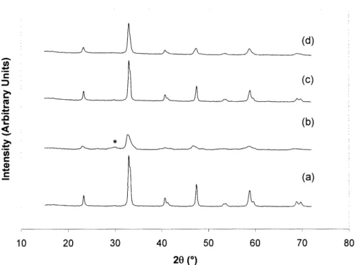
2.8 XRD pattern of LaNiO3after subjected to 4000C reaction with a feed of (a) 5% 34
methanol and 1.5% oxygen, (b) 5% methanol and 7.5% H20, and (c) 5% methanol, 1.5% oxygen and 7.5% H20. XRD pattern of fresh LaNiO3 catalyst is shown in (d). XRD peak for the main lanthanum carbonate peak is denoted by *
2.10 Transmission electron micrograph (JEOL 2010, 200 kV) of (a) LaNiO3 and (b) 35
LaNio.7 5A1.02503after exposure to 5% hydrogen for 6 hours at 650°C.
2.11 XRD pattern of (a,b) LaNiO3and (c,d) LaNi0.7 5A1.02 503 (a,c) before and (b,d) after 36 methanol partial oxidation at 4000C without steam addition. The main lanthanum carbonate peak is denoted by *.
2.12 (a) Conversion and (b) hydrogen and (c) carbon dioxide selectivities for oxidative 37 steam reforming of methanol over () LaNiO3, (A) LaNio.07 5A1.02503, and ()
LaNio.9 5Co0.0503. The reaction was conducted at a space velocity of 500,000 hr-'
with a 5% methanol feed, a water/methanol ratio of 1.5, and an oxygen/methanol ratio of 0.3.
2.13 (a) Conversion and (b) hydrogen selectivity for oxidative steam reforming of 39 methanol over () LaNiO3, () LaNio.9 5Co0.0503, and (A) 5 wt% Pd/A1203. The
reaction was conducted at a space velocity of 500,000 h-' for LaNiO 3 and
LaNio.9 5Co.0500 3 and 200,000 h-' for 5 wt% Pd/A1203, with a 5% methanol feed, a water/methanol molar ratio of 1.5, and an oxygen/methanol molar ratio of 0.3.
2.14 (m) Conversion, () hydrogen and (A) carbon dioxide selectivities, and (X) post- 42 bed temperature for oxidative steam reforming of methanol over (a) LaNiO3, (b) 5 wt% Pd/A1203, and (c) LaNio0 9 5Co0.0o503 under full-fuel conditions. The reaction
was conducted at a space velocity of 1,500,000 h- 1with a water/methanol molar ratio of 3 using simulated air as the oxygen source.
2.15 (m) Conversion, () hydrogen and (A) carbon dioxide selectivities, and (X) post- 43 bed temperature for oxidative steam reforming of methanol over alumina-diluted
LaNiO3bed under full-fuel conditions. The reaction was conducted at a space velocity of 550,000 h-' with a water/methanol molar ratio of 3 using simulated air as the oxygen source.
2.16 LaNiO3 film was deposited with fine porosity to catalyze conversion without 44 substantially lowering the permeability of the underlying Pd membrane.
2.17 (m) Hydrogen and (A) carbon dioxide selectivities obtained on the reformate side 45 of the Pd membrane microreactor at 4000C. The reaction was conducted at a space velocity of 350 L/(gcathr) using a dilute 4% methanol feed without steam addition.
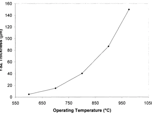
3.1 YSZ electrolyte thickness required to limit area-specific resistance to 0.15 Q2cm2 at 49
various operating temperatures.
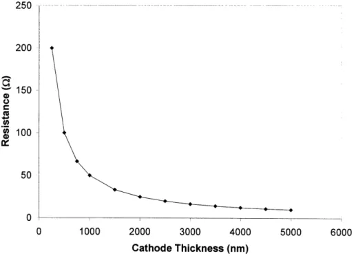
3.3 Calculated resistance of a dense LSM cathode at 6000C for a 550 nm x 550 nm 50 YSZ electrolyte with parallel current collectors
3.4 Possible binding configurations in metal carboxylates: (a) monodentate, (b) 53 chelating, (c) bridging, and (d) bridging-chelating configurations.
3.5 LSCF films coated onto Si substrates at (a) 1000 rpm, (b) 2000 rpm, (c) 3000 rpm, 57 and (d) 4000 rpm.
3.6 Viscosity of the acetate precursor solution for SDC at a NH40H/acetate molar ratio 58
of(+) 0, (X) 0.8, () 1.6, (A) 2.5, () 3.3, and () 4.1.
3.7 Viscosity of the acetate precursor solution for SDC at a NH40H/acetate molar ratio 59
of (+) 0, (X) 0.8, () 1.6, (A) 2.5, (*) 3.3, and () 4.1, after subtracting the viscosity of the ammonium hydroxide solution.
3.8 Intrinsic viscosity of the acetate precursor solution as a function of the 60 NH4OH/acetate molar ratio.
:3.9 AFM of 400°C-calcined SDC film. 61
:3.10 Viscosity () and adhesion strength () of the 400°C-calcined SDC films as a 62 function of the NH40H/acetic acid molar ratio in the MOD SDC acetate solution.
3.11 Particle size of YSZ precipitates achieved at different base equivalents, measured 64
(*)
for the centrifuge supernatant and () after resuspension with a homogenizer.3.12 Gelation time for mixed zirconia and yttria sols with different yttria contents. 65 3.13 Adhesion strength of 550°C-calcined LSCF/YSZ composite films containing (a) 0 66
wt%, (b) 10 wt%, (c) 20 wt% and 30 wt% YSZ, prepared without YSZ (black), with 0.4-jtm YSZ (dark grey), and with 8-jtm YSZ (light grey).
3.14 Surface morphology of a 550°C-calcined, thick LSCF/YSZ film produced with 30 66 wt% coarse-grained YSZ.
3.15 Electrical conductivity of the 550°C-calcined LSCF/YSZ composite films 67 containing (a) 0 wt%, (b) 10 wt%, (c) 20 wt% and 30 wt% YSZ, prepared without YSZ (black), with 0.4-jtm YSZ (dark grey), and with 8-jtm YSZ (light grey).
3.16 Porous Pt film produced from commercial Pt paint. 68
3.18 EDX spectrum of the thin Pt-Ni film (a) before and (b) after etching away Ni in hot 69 nitric acid.
3.19 AFM image of a porous PMMA film (image area: 5 tm x 5 gm). 70
4.1 (a) Electrolyte-supported and (b) electrode-supported architectures. 74
4.2 Schematic of (a) a conventional cermet anode, and (b) a cermet anode made from a 76 MIEC material.
4.3 Methane conversion over () undoped ceria, and ceria doped with 20 at% () Y, 85 (A) Zr, () Sc and (+) Ca at 65,000 hr'l with a CH4/02molar ratio of 2.
4.4 Methane conversion over () undoped ceria, and ceria doped with 20 at% () Pr, 86 (+) Sm and (A) Tb at 65,000 hr-' with a CH4/02 molar ratio of 2.
4.5 XRD patterns of praseodymia (a) as-prepared (pure PrO2phase), (b) after firing at 88
800°C in air (mixed PrO2 and Pr6Oll phases), and (c) after sintering at 14000C in
air (pure Pr6011 phase). A silver internal standard was used.
4.6 XRD patterns of 800°C-calcined CeO2/LaCrO3 composites with (a) 100, (b) 80, (c) 89
60, (d) 40, (e) 20 and (f) 0 vol% LaCrO3. A silver internal standard was used.
4.7 Grains sizes of CeO2(black) in CeO2/LaCrO3 nanocomposites calcined at 800C in 89
air, and CeO2 (dark grey) and LaCrO3 (light grey) in CeO2/LaCrO3 nanocomposites
reduced at 8000C in hydrogen.
4.8 (n) Cubic lattice parameter and () volume expansion in ceria for the 1400°C- 90 sintered CeO2/LaCrO3composites.
4.9 Pore size distributions of 400°C-calcined Sm-doped ceria particles subjected to () 92 IC, () MC and (A) MH treatments. Inset: Illustration of oxide sedimentation from a dispersed state (top) and a flocculated state (bottom) [64].
4.10 (a) Nitrogen adsorption-desorption isotherms and (b) tapping densities of 400°C- 93 calcined Sm-doped ceria particles subjected to (i) IC, (ii) MC and (iii) MH treatments.
4.11 (A) Normalized diameter and () % residual shrinkage of calcium titanate anode 95 support as a function of processing temperature.
4.12 Cross-sections of an anode-supported SOFC: (i) La-CaTiO 3 anode, (ii) Sm- 95
CeO2/La-CaTiO 3composite anode interlayer, and (iii) YSZ electrolyte
4.13 Cell potential (solid lines) and power density (dashed line) as a function of current 97 density at 900C for Sm-CeO2/La-CaTiO3 composite anode interlayer containing
(A) 2.5 wt% Ni, () 2.5 wt% Co, (X) 2.5 wt% Cu, and (4, m) 0.5 wt% Cu. The
studies were conducted in humidified hydrogen (, , x, 4) or humidified methane (m).
4.14 XRD patterns for (a) Ni-Sn/YSZ cermet prepared by reduction of the oxide 98 composite, and (b) Ni-Sn/YSZ cermet and (c) Ni/YSZ cermet after exposure to dry methane at 800C. Ni3Snl (1), Ni3Sn2 (2), Ni (+), YSZ (*), and carbon (#) peaks
are denoted.
4.15 Dimensional increase (solid lines) and weight increase (dashed lines) in () 99 Ni/YSZ and () Ni-Sn/YSZ cermet anodes after exposure to dry methane at 800°C
for 1.5 h.
4.16 Optical micrograph of Ni-Sn/YSZ anode-supported YSZ electrolyte (a) before and 99 (b) after exposure to dry methane at 8000C for 1.5 h. Cells are 2 cm in diameter.
4.17 Electrical conductivity of the Ni-Sn/YSZ cermet (with 40 mol% Sn) as a function 100 of alloy loading in the cermet and the fraction of coarse-grained YSZ particles used.
4.18 Cross-section of a reduced anode-supported SOFC with (a) Pt contact layer, (b) 101
LSM/YSZ composite cathode, (c) YSZ electrolyte, (d) Ni-Sn/YSZ anode
interlayer, and (e) Ni-Sn/YSZ anode support.
4.19 Cell potential (solid lines) and power density (dashed lines) for Ni-Sn/YSZ anodes 102 synthesized using () 100 wt%, () 50 wt% and (A) 0 wt% coarse-grained
powders for YSZ. The studies were conducted in humidified hydrogen at 800C.
4.20 Cell potential (solid lines) and power density (dashed lines) for (a) Ni-Sn/YSZ and 103 (b) Ni/YSZ anodes in humidified hydrogen at () 7000C, () 750C and (n) 8000C.
4.21 Cell potential (solid lines) and power density (dashed lines) for Ni-Sn/YSZ anode- 104 supported cell in humidified methane at (0) 7000C, (A) 750C and () 800°C.
4.22 Oxidation growth of the Ni-Sn/YSZ cermet (with 40 mol% Sn) at 8000C as a 104 function of the alloy loading in the cermet and the fraction of coarse-grained YSZ particles used.
List of Tables
3.1 Recommended firing temperatures of commercially available electrode inks. 51
3.2 Base equivalent and the respective final pH based on titration. 63
4.1 Material properties of potential anode additives to improve the coke tolerance of 81 Ni/YSZ cermets.
4.2 Characteristics of commercial YSZ powders prepared by grinding (Unitec) and 81 chemical coprecipitation (Tosoh).
4.3 Range of parameters investigated in developing the Ni-Sn/YSZ cermet. 84
4.4 Rate of methane conversion at 750C and a CH4/02 molar ratio of 2. 87
4.5 Effect of processing atmosphere on the mechanical stability of pure and doped ceria 87 and praseodymia.
Chapter 1 - Background and Research Motivation
1.1. Introduction
Worldwide energy consumption is expected to grow by 54% by 2025 [1]. Both new energy sources and advanced technologies for more efficient power conversion would be needed to meet this demand. Fuel cells are of great interest as they could convert fuels directly to electricity without moving parts. They produce power from the electrochemical combustion of a stream of fuel and oxidant.
Fuel cells are being developed for many applications. They are often associated with the hydrogen economy. However, such fuel cell systems are limited by the energy density of hydrogen and the lack of fueling infrastructure. Nevertheless, two types of fuel cells are of interest for further development, polymer electrolyte membrane (PEM) and solid oxide fuel cells (SOFC). Low-temperature PEM fuel cells are applicable as battery replacements for many portable devices. High-temperature SOFC systems are targeted for combined heat power applications.
In PEM fuel cells, the polymer electrolyte conducts protons produced at the anode from hydrogen. In contrast, oxygen ions are transported in SOFC through a ceramic electrolyte (see Figure 1.1). Oxygen from the air feedstream is reduced to 02- species at the cathode. The electrons required for this reduction are supplied from the oxidation of 02-at the anode. Electrons 4) LL rQ -W4 it
0
kV0
0 X SE 02-I
Figure 1.1. Schematic of a SOFC.
4
6
C"
1.2. Hydrogen Generation for PEM Fuel Cells
PEM fuel cells typically require ultrapure hydrogen as a fuel. Noble metal catalysts are needed for the low-temperature oxidation involved. These materials are easily poisoned by CO. The fuel cell's power density at 0.7 V may be reduced by 45% in the presence of 50 ppm of CO [2]. As hydrogen is mainly generated from hydrocarbon reforming, this presents some challenges. Hydrogen storage has limited capacity for many applications, and successful reforming schemes typically require complicated engineering.
Portable hydrogen generators often use partial oxidation to reform hydrocarbons to hydrogen. The exothermic nature of partial oxidation also allows for rapid start-up and simpler reactor design compared to steam reforming. As partial oxidation creates large quantities of CO, the water-gas shift reaction is often employed to lower the CO concentration to acceptable levels. Copper is by far the most active metal for the water-gas shift reaction. However, dispersed copper is highly pyrophoric. Rapid reoxidation of the shift bed can result in temperature rises of 800-900°C [3]. Industrially, the shift catalyst is decommissioned slowly using 0.1% oxygen in steam over the course of 24 h. This is clearly not practical in a reactor designed for numerous on/off cycles.
Therefore, alternative catalysts should be developed for the generation of hydrogen from methanol. They would not involve expensive noble metal or pyrophoric copper catalysts. Potential catalysts were screened for high volumetric activity and tested in a plug flow reactor without a pre-reduction step. This would illustrate if these catalysts would be suitable for portable hydrogen generation. La-based perovskites were selected as the catalyst candidates. They were examined for sustained autothermal conversion of methanol to hydrogen by oxidative reforming. The optimized catalyst was also developed as a coating for application in a micro-reactor equipped with a Pd membrane, so as to demonstrate the possibility of hydrogen generation and purification in one unit operation on the micro-scale.
1.3. SOFC
SOFC systems show good power densities with hydrogen. They can also operate on hydrocarbon fuels. However, hydrocarbon utilization typically requires internal
reforming. Sufficient steam is fed with the hydrocarbon to generate hydrogen and carbon oxides over a nickel-based anode. This system suffers from mechanical problems due to the large endotherms associated with the reforming process [4]. Significant stresses are developed due to mismatch in thermal expansion coefficient between the electrolyte and electrode layers.
An unavoidable drawback of SOFC is that the fuel stream is diluted by the oxidant stream, greatly lowering the power density obtained and ultimately limiting the fuel conversion to < 80%. Higher fuel utilization would result in oxidation and spallation of the Ni/YSZ anode. As power density determines the size and the cost of the fuel cell stack required for a particular power rating, maximizing the power density would lead to a compromise in overall system efficiency. Figure 1.2 shows the decrease in the power density with increasing hydrogen utilization for one of the most advanced anode-supported fuel cells operating at 0.7 V [5].
1.8 1.6 1.4 E !o 1.2 >, 1.0 mA 0.8 0) 0.6 . 0.4 0.2 0.0 0 20 40 60 80 Fuel Utilization (%) 100
Figure 1.2. Power density versus fuel utilization for advanced anode-supported SOFC operating on hydrogen at 8000C [5].
1.3.1. Micro-Solid Oxide Fuel Cells
By miniaturizing their components, SOFC systems may be designed in a form factor capable of battery replacement for certain applications. Conventional ceramic processing techniques have produced yittria-stabilized zirconia (YSZ) electrolytes of 10-20 pm-thick. Deposition techniques used in semiconductor processing (such as sputtering, pulsed laser deposition and e-beam deposition) have enabled the generation of self-supporting YSZ electrolytes of 100-400 nm-thick. Such a dramatic decrease in electrolyte thickness would allow for lower temperature operation and reduce the system's thermal mass, greatly shortening the start-up time of the device.
Although the semiconducting processes are adept at producing dense films, they cannot generate high surface area porous electrodes easily. Therefore, wet-chemical techniques were developed for depositing electrodes for micro-solid oxide fuel cells (pSOFC). Traditional SOFC systems utilize organic binders in applying ceramic powders to the electrolytes. Calcination is then used to partially sinter the electrode layer to promote adhesion. The high temperatures involved are beyond the design limitations of the jSOFC materials. Thus, techniques for oxide wash-coats were developed to allow for low-temperature film adhesion. Besides establishing novel methods of deriving oxide-based electrodes, we have also examined approaches to create nanoporous noble metal films for low-temperature cathode applications. These systems would be of
interest for their high electrical conductivity and intrinsic catalytic activity.
1.3.2. Direct Hydrocarbon Fuel Cells
Although the main attraction of SOFC systems is their ability to process many fuel streams, the fuel choice is most often a reformate stream. This is due to limitations of the current Ni/YSZ anode. When dry methane is used as the feedstream, rapid coking would cause the Ni/YSZ layer to fracture after only 10 min at 800C. Ni metal is also not capable of being reoxidized without mechanical failure. Therefore, we have examined alternative anode-supported SOFC systems that would address these concerns through novel anode formulations.
Besides their electrochemical performance, the anode materials must have well-matched thermal expansion coefficients as the YSZ electrolyte, and must not react with
YSZ at the 1400°C fabrication temperature. Three different anode materials were investigated. The first two anode materials utilized all-ceramic formulations, and could be reoxidized. In the first case, LalxSrxCrl-yMgyO3 and doped ceria were used as the electrical conduit and ionic conductor, respectively, to form a composite mixed conductor. To maximize the active interface between the doped ceria and lanthanum chromate, the two ceramics were processed as a nanocomposite instead of a physical mixture. Besides this system, we have examined a second all-ceramic system, which consisted of an electrically conductive La-doped CaTiO3 and doped ceria.
The third anode material studied was Ni-Sn/YSZ. This cermet utilized a Ni-Sn alloy to minimize the coking problem. Its coke resistance and dimensional stability in dry hydrocarbon were compared to those of the conventional Ni/YSZ system. The resulting anode-supported SOFC was examined for operations involving humidified hydrogen and humidified methane.
1.4. References
[1] International Energy Outlook 2004, DOE/EIA-0484 (2004). [2] Fuel Cell Handbook 6, DOE/NETL-2002/1179 (2002).
[3] Twigg, M.V., "Catalyst Handbook Second Edition," p. 330, Manson Publishing, London, 1996.
[4] Achenbach, E., J Power Sources 49, 333 (1994).
[5] Virkar, A.V., "Polarization in Anode-Supported Solid Oxide Fuel Cells," Boston University Emerging Technology Seminar, May 30, 2003.
Chapter 2 - Nanocrystalline Perovskites for Oxidative Steam Reforming of Methanol
2.1. Introduction
Due to current limitations in battery technology, polymer-based fuel cells are developed to provide high power densities from hydrogen fuel. Unlike stationary reactors, portable reforming systems must utilize a fuel that can produce pure hydrogen in a minimal number of unit operations. Methanol is an ideal fuel for such application. It has a high energy density, is a liquid available free of impurities, and can be reformed easily at temperatures below 4000C.
The low-temperature water-gas shift catalyst can be employed to produce hydrogen from methanol steam reforming [1]. The water-gas shift reaction increases the hydrogen yield of reformate streams at the expense of CO. The copper-based catalyst for this reaction suffers from the exothermicity of the reduction step; when rapidly reduced with hydrogen, a temperature rise of 500°C may be experienced. When rapidly shut down in air, an uncontrolled oxidation can produce temperatures of 800-900°C due to the pyrophoric nature of the copper catalysts [2]. These exotherms can be avoided industrially using slow reduction and oxidation steps, but such operations would not be practicable in portable reforming applications. Thus, a novel catalyst system is needed to work stably under transient operations and frequent reactor cycling.
Additional challenges exist for portable power applications. First, hydrogen is not typically available to pre-reduce the traditional reforming and water-gas shift catalysts. Secondly, a CO remediation technique must be employed to keep CO levels below 100 ppm throughout the reactor lifetime [3]. Lastly, a high degree of system integration is needed to
ensure a small form factor.
Methanol partial oxidation is the focus of this study due to its quick start-up and autothermal operation. Steam may be added to the methanol feed to boost the hydrogen selectivity, while lowering the maximum reaction temperature [4]. Various classes of metal catalysts were screened for volumetric activity with the constraint that the system might not utilize a pre-reduction step, and should not contain significant quantities of copper or noble metals. The optimized catalyst systems were then applied to a Si-based microreactor with a Pd membrane for the production and purification of hydrogen in one unit operation. Problems associated with the oxidation and methanol poisoning of the Pd membrane were avoided by utilizing a uniform active catalyst coating.
2.1.1. Classification of Methanol Reaction Schemes
Hydrogen can be produced from methanol by steam reforming, partial oxidation, or endothermic dissociation. The steam reforming reaction is preferred because it has the highest fuel efficiency and produces the least CO.
CH3OH(g)+ H20 -> 3 H2 + CO2 (1)
The high efficiency results from the water-gas shift reaction, which combines CO and excess water to produce hydrogen and carbon dioxide. Steam reforming is endothermic, and has a slower reaction rate compared to partial oxidation [5]. Typical industrial catalysts for methanol steam reforming are copper-zinc oxide supported on alumina.
Partial oxidation of methanol is exothermic, and can produce hydrogen without an external heat supply [6]. The reaction scheme includes the decomposition of methanol to CO and hydrogen, followed ideally by the selective oxidation of CO.
CH3OH(g) + /2 02 - 2H2 + CO2 (2)
This reaction [7] is not as well studied as steam reforming. The most active catalysts are supported copper and palladium.
Endothermic dissociation of methanol can be used to produce synthesis gas. An additional step would be required to convert the high CO content.
CH3OH(g) 2 H2 + CO (3)
Supported molten salt catalysts have shown great stability for this reaction [8]. Other catalysts for this reaction include copper/chromia.
2.1.2. Reforming Catalysts
Nickel metal catalysts are typically used in the reforming of hydrocarbons. They can be difficult to reduce, especially when supported on alumina. Their reduction is performed with hydrogen at temperatures above 600°C. Noble metal catalysts are more active and expensive than the nickel catalysts. The reforming activity with toluene as the model reactant is given by Rh > Ir > Pt > Ru. In general, active reforming catalysts would show little activity for the water-gas shift reaction [9].
over-reduced to FeO and metallic iron, which are less active. This system can be operated at 340-400°C, and would sinter at higher temperatures. The reduced catalyst is also pyrophoric, and re-oxidation can lead to an adiabatic temperature rise of 450°C. Therefore, re-oxidation is industrially performed slowly in a dilute air stream at low temperatures [2].
The modern copper-based low-temperature shift catalyst was introduced in 1960, and has been optimized to improve the thermal stability and poisoning resistance [10]. It is operated below 260°C to limit copper sintering. Industrially, its reduction is performed over a period of 12-24 h to prevent catalyst over-heating. Before discharge, the catalyst is re-oxidized with a dilute (0.1%) air stream so that the heat produced may be removed safely [2]. These controlled reduction/oxidation steps are not feasible in a cyclic portable system. The danger of large exotherms would prevent copper from being used as the primary catalyst component in portable reforming.
2.1.3. Catalyst Design
Although high hydrogen selectivity is desired, methanol steam reforming and water-gas shift reactions are not likely to be utilized in a compact portable system since they require copper-based catalysts. The low-temperature activity of copper towards the shift reaction is quite unique [ 11 ]. Therefore, our attention is turned towards partial oxidation of methanol.
Traditionally, noble metal systems are utilized for the partial oxidation reaction as they facilitate light-off and ensure continued autothermal operation. However, their cost is too prohibitive for most applications. This study focuses on non-noble metal combustion catalysts that belong to the perovskite family. These catalysts are employed in an oxygen-poor environment to limit complete oxidation.
CO mitigation for this application has been addressed industrially by using excess oxygen feed. Casio has presented a clean-up bed with an 02/CO ratio of 40 [12]. Such a high excess air concentration significantly dilutes the fuel content entering the fuel cell. Alternatively, selective CO oxidation has been explored. These occur optimally below room temperature, and therefore are not realistic [13]. In this study, a palladium membrane is employed at the reaction temperature to remove CO from the reformate stream.
2.2. Experimental
2.2.1. Reactor Design and Reaction Conditions
A packed bed reactor was constructed to study the partial oxidation of methanol. Vaporization of low levels of steam and methanol could lead to substantial feed fluctuations. Such fluctuations were reduced to 5% by using a heated dead volume after the pre-heater. The oxygen stream was introduced post the dead volume to avoid possible reactions within the dead volume; blank runs indicated no conversion up to a furnace temperature of 600°C. Liquid reactants were introduced using a Harvard Apparatus syringe pump. Gas flow rates were controlled with MKS mass flow controllers. The reactor effluent was analyzed after a condenser using an Agilent 6890 gas chromatograph equipped with a mole-sieve and Carbowax columns. Reaction temperature was controlled with a thermocouple inserted just below the catalyst bed.
Nitrogen was added to the carrier gas as an inert standard to allow for accurate determination of the product distribution. Methanol feed concentration was fixed at 5% in the catalyst development studies. This level represented a good compromise that provided a uniform feed stream. Lower methanol concentrations would be desirable to further reduce the possibility of heat effects, but they would lead to unacceptably large data fluctuations.
For catalytic studies, the oxygen/methanol ratio was set at 0.3 to minimize heat effects due to the reaction. The steam/methanol ratio was 1.5. Under these conditions, catalytic activities were initiated at 4000C, and then brought to lower temperatures. Catalysts were pelletized and crushed to 60-80 mesh before testing. All runs utilizing a 5% methanol feed involved 75 mg of catalysts kept between quartz wool plugs. For the perovskite catalysts, this corresponded to a space velocity of 500,000 hr'l. Optimized catalysts were compared to a commercial 5 wt% Pd/A1203 catalyst (Sigma). Following the convention of this field, hydrogen selectivity was based on the stoichiometry of partial oxidation [14]. If significant water-gas shift activity was present, the hydrogen selectivity could exceed 100%.
Full-fuel conditions were studied to examine both the exothermicity of the reaction and the ability of non-noble metal catalysts to sustain autothermal conversion. A liquid fuel with a water/methanol ratio of 3 was utilized to keep the stock solution non-flammable. A simulated air stream was used whereby nitrogen was replaced by 4% nitrogen in helium, and blended with pure oxygen to allow for evaluation of the mass balance. The catalyst powders were pelletized
liquid at room temperature or as a preheated gas at 1400C. A syringe pump was used to feed the liquid precursors through the low-volume 1/16" stainless steel tubing.
Reactions in the microreactor with palladium membrane utilized a bubbler to introduce the feed as the flow rates were - 10 sccm. Both chilled and room-temperature saturators were employed to produce methanol concentrations of 4% and 13%, respectively. A helium sweep was used on the permeate side, and the reformate was analyzed using a mass spectrometer. Details on the fabrication of the microreactor were published elsewhere [ 15].
2.2.2. Synthesis and Characterization of Catalysts
Catalysts were synthesized by techniques previously reported [16]. In general, a salt solution of the desired composition was added slowly to a base solution consisting of tetraethylammonium hydroxide (Alfa Aesar) in isopropanol. After aging, the precipitate was rinsed with isopropanol, dried and calcined to 800C. The tetraethylammonium hydroxide was used in place of sodium hydroxide in this synthesis to avoid sodium contamination.
Catalyst coatings for the microreactor were obtained by dispersing the calcined and milled powder in methanol using a sonicator. Prior to application, a blend of catalyst and alumina (Nyacol, 50 nm) (8:1 weight ratio) was used to bind the oxide to the microreformer membrane.
X-ray diffraction (XRD) patterns of the catalysts before and after reaction were obtained with a Siemens D5000 Diffractometer (45 kV, 40 mA, Cu-Ko). Surface areas were measured using a 5-point BET (Brunauer-Emmett-Teller) method on a Micromeritics ASAP 2000 instrument. Temperature-programmed reduction was performed in a Perkin-Elmer Series 7 TGA with 2.5% hydrogen in helium at 300 sccm.
2.3. Results and Discussion
2.3.1. Thermodynamics of Oxidative Steam Reforming
Since low-temperature PEM fuel cells could be easily poisoned by CO, thermodynamics were used to understand the effect of reaction conditions on CO production. Where possible, purification processes should be avoided if the reaction conditions would allow for sufficient CO
mitigation. The reaction thermodynamics were examined with the non-stoichiometric method. The heat and entropy of formation and the heat capacity for the various gases were taken from
the NIST database. All gases were considered ideal. Thermodynamics of methanol steam reforming have been published previously [17], but thermodynamics of oxidative steam reforming have not been reported.
In the partial oxidation regime without water addition, methanol conversion was complete above a temperature of 230°C. As the temperature increased, the selectivities to CO2 and hydrogen decreased, which could be attributed to the slight exothermicity of the water-gas shift reaction. Numerous species were involved in the original model, including methane, carbon, methyl formate and dimethyl ether. Figure 2.1(a) shows the results of the full model at 600 K and 1 bar for various methanol concentrations in air. 12.3 mol% methanol feed corresponded to stoichiometric combustion, while 100% methanol feed corresponded to methanol dissociation. The major species produced at low oxygen contents were water, carbon and methane in the full thermodynamic model. Methanol was known not to coke as its C-O bond would not be broken through heterogeneous reactions [18]. Methane, however, has been observed in some reaction schemes in sub percent quantities, and was produced through a methanation mechanism [19]. As a result, a simplified model was examined that included only the main species: hydrogen, water, CO, carbon dioxide, methanol and nitrogen (Figure 2.1 (b)).
A wide range of oxygen and water ratios was studied to understand the effect of having these two reactants in the same bed (see Figure 2.2). A grid of conversions was calculated at oxygen/methanol ratios of 0.00-0.75, and water/methanol ratios of 0-3. The reaction was examined at 1 bar and 500, 600, 700 and 800 K. An additional grid of data was taken at 5 bars and 600 K to determine the pressure effects. Such effects were minor and did not provide sufficient CO remediation.
High water/methanol ratios were favorable towards maximizing hydrogen and minimizing CO production. The presence of oxygen lowered hydrogen selectivity, but helped CO remediation. In general, water/methanol ratios should be > 1, with sufficient oxygen levels to keep the process exothermic for autothermal operation (02/methanol ratio > 0.3). However, it was not possible to keep the CO levels below 100 ppm under the conditions investigated. This meant that excessively high water and/or oxygen contents would have to be introduced to the feed to lower the CO levels. High water contents would not be feasible since a large amount of energy would be needed to vaporize the feed stream. The reformate would also be diluted with
PEM fuel cells, a Pd-based membrane purifier was chosen over a chemical means for CO removal. (a) 100 80 60 o 40 20 0 0
V
,
20 40 60 80 100Mol% Methanol in Air
(b) 100 80 60 o .51 40 20 0 0 20 40 60 80
Mol% Methanol in Air
Figure 2.1.
100
(a) Full and (b) simplified thermodynamics model of methanol reaction in air to produce () H20, () H2, () CH4, () CO2, (0) carbon and (X) CO at 600 K and 1 atm.
(a) 3.0 2.5 2.0-0 2 1.5 1 0.5 2. 0.0-1 0.00 0.15 H2OIMeOHin 0.30 Feed 0.45 0. r 0 Feed 0.60 02 / MeOH in Feed 0.75 (b) ,1 0 0 0 0 0 0 100000 E 10000 X
0
-1000 0.00 0.15 _ 100 0.30 3 0.45 0.60 2 O2 / MeOH in 0.75 1 Feed 0 H20 / MeOH in FeedFigure 2.2. Thermodynamics model of oxidative steam reforming of methanol at 500 K and 1 bar.
2.3.2. Adiabatic Temperature Rise
The maximum possible temperature rise was evaluated to understand the effect of various feed conditions on the reaction temperature. Short contact time exothermic partial oxidation reactions approach the adiabatic conditions [20]. For comparison, stoichiometric partial oxidation of methane has a heat of reaction of -36 kJ/mol. Methanol partial oxidation has a much larger heat of reaction of -192 kJ/mol, and a larger flammability window in air.
To obtain an upper bound on the reaction temperature, the adiabatic temperature rise was calculated based solely on oxidation mechanisms. The slower endothermic dissociation and steam reforming reactions were not involved in the calculation as they would not have time to reach equilibrium at the space velocities typically employed [14]. Complete CO oxidation was calculated prior to hydrogen consumption as CO oxidation was more exothermic than hydrogen oxidation. The lower bound of perfect hydrogen oxidation selectivity reduced the curves
slightly, but did not alter the results considerably.
Figure 2.3(a) was based on feeding gaseous reactants at 1400C, with air as the oxygen source. Figure 2.3(b) involved liquid feed stream and used the exothermicity of the reaction to vaporize the reactants in situ at the reaction zone. Some researchers have utilized a liquid feed to help cool this reaction and limit the bed temperature [4].
In vitiated air, hydrogen would ignite at 610°C, while CO and methanol would ignite at 758°C and 820°C, respectively [21]. Thus, when the reaction temperature exceeded these temperatures, homogeneous combustion of hydrogen would be expected. Commercially, the Johnson Matthey HotSpot reactor utilizes the presence of large exotherms to quickly reduce methanol concentrations [22]. However, if a water-gas shift bed is not employed, heat must be removed from the reactor to minimize the occurrence of homogeneous reactions and the loss of hydrogen selectivity.
0.0 0.2 0.4 0.6 0.8 O2/Methanol Molar 1.0 Ratio 1.2 1.4 1.6 0.0 0.2 0.4 0.6 0.8 1.0
O2/Methanol Molar Ratio
1.2 1.4 1.6
1.2 1.4 1.6
Figure 2.3. Adiabatic temperature rise liquid reactants, using a water/methanol oxygen source.
with (a) preheated gaseous reactants molar ratio of (+) 0.0, () 1.5 and (A)
at 140°C, and (b) 3.0 with air as the
(a) LDUU 2000 O a 1500 E 1000 500 0 (b) 2000 2000 150 0 E 15000 500 -rnn
nrrnr ..I ... r I .. ... . .. ... .. ..I. ... .. . .. .. ...I. ... .. . .. .. .. ... ... .I. .. ... ... .. I. ..I. ... .... .. .. .. ... .. I. .... .... ..
nI
2.3.3. Preliminary Studies
Many classes of materials were screened for the partial oxidation of methanol without water addition. Initial studies examined the activity of copper catalysts, which performed quite well but showed significant deactivation over time. A simple comparison of copper- and nickel-based catalysts were performed by synthesizing copper and nickel aluminates with excess transition metal content (M/A1 = 0.625). These two aluminates were examined at 3250C due to
the low-temperature constraint of the copper-based catalyst (see Figure 2.4). IUU 90 80 70 60 5O
I 40
30 20 10 0 0 100 200 300 400 500Time on Stream (min)
Figure 2.4. Hydrogen yield for methanol partial oxidation without steam at 3250C over () copper aluminate and () reduced nickel aluminate at 200,000 hr-' with a 5% methanol feed and an oxygen/methanol molar ratio of 0.3.
Nickel aluminate has been successfully used for the steam reforming of methane [23]. However, it could not be reduced by methanol at the reaction temperature, and the unreduced catalyst produced dimethyl ether possibly over the acidic alumina sites. When nickel aluminate was reduced with hydrogen at high temperatures prior to catalytic testing, it produced dimethyl ether and hydrogen. After reaction, the catalyst could be exposed to air and re-used without another reduction step.
The nickel aluminate catalyst was found to be much more stable than the copper aluminate catalyst. Better copper-based catalysts were synthesized, but they all exhibited rapid
deactivation over time. In particular, barium was found to be an active promoter for this reaction [24]; copper/ceria also performed well [25]. These copper-based catalysts all led to high initial hydrogen yields, but could not achieve stable activity.
2.3.4. The La-based Perovskite System
The best non-noble metal catalyst developed by us belonged to the perovskite family. Perovskites (ABO3) have a complex crystal structure that accommodated a great variety of compositions. Lanthanum was used for the A-site since La-based perovskites have been applied as combustion catalysts with good light-off characteristics and thermal stability [26]. Nickel, iron, cobalt and manganese were used at the B-site, which could be further doped to improve the catalyst stability in reducing atmospheres.
The La-based perovskites showed that their activity towards methanol partial oxidation was heavily dependent on the B-site composition (Figure 2.5). Superior hydrogen yield was attained by LaNiO3, which demonstrated full methanol conversion under the conditions tested with a hydrogen/methanol molar ratio of 2. Only CO2, CO, H2 and H20 were obtained over the
LaNiO3 and LaCoO3 catalysts; no methane or dimethyl ether was observed. Though active for methanol conversion, LaMnO3 produced only combustion products with negligible hydrogen yield.
For reference, a NiO/NiAl204 catalyst was also shown in Figure 2.5. It contained the same Ni loading by weight as the LaNiO3 catalyst and was not pre-reduced. As noted in Section 2.3.3, the unreduced NiO/NiAl204 only produced dimethyl ether in the absence of water. Introduction of steam decreased the dimethyl ether yield, and resulted in hydrogen production with high carbon dioxide selectivity.
IUU 80 60 '0 . 2 40 20 -AI , . . . . . .. . .. v v... U X--X-xX--- X-X-,-x-X- -x--x-x.--0 100 200 300 400 500
Time on Stream (min)
Figure 2.5. Hydrogen yield for methanol partial oxidation at 4000C over () LaNiO 3, (-) LaCoO3, (A) LaFeO3, (X) LaMnO3, and () NiO/NiAl20 4. The reaction was conducted at a
space velocity of 500,000 h with a 5% methanol feed, a water/methanol molar ratio of 1.5, and an oxygen/methanol molar ratio of 0.3.
2.3.5. Effect of Reaction Environment on LaNiO3
To understand what reaction processes occurred over the LaNiO3perovskite catalyst, the effect of reaction environment was investigated (see Figure 2.6). This catalyst showed the highest activity for the methanol partial oxidation; steam lowered the activity of methanol partial oxidation at low temperatures. LaNiO3 was less active for the dissociation and steam reforming of methanol. However, since these two endothermic reactions would occur under the reaction conditions, they were expected to contribute towards the observed selectivities.
The ability of steam to increase the selectivity of the partial oxidation reaction is illustrated in Figure 2.7. At 400°C, the CO selectivity rose from 33% to 64% in the presence of steam. This suggested a significant contribution from the water-gas shift reaction to the selectivity observed at a feed oxygen/methanol molar ratio of 0.3. Further increase in the oxygen/methanol molar ratio would decrease the CO selectivity, but CO was never eliminated in the partial oxidation reaction. At the stoichiometric oxygen/methanol molar ratio of 0.5, the carbon dioxide selectivity only rose to 84%, but the hydrogen selectivity decreased to 91%. At
the high space velocities employed, the ability of the water-gas shift reaction to move the system towards equilibrium was limited [14].
,4 no' Iuu 80 60 c ,_ a) = 40 0 20 0 200 250 300 350 400 450 Temperature (C)
Figure 2.6. Conversion of methanol over LaNiO3 for a feed stream containing (n) 5% methanol and 1.5% oxygen, (+) 5% methanol, 1.5% oxygen and 7.5% H20, (A) 5% methanol, and (0) 5%
methanol and 7.5% H20.
The effect of high temperature and hydrogen generation on the perovskite catalyst was examined. Some surface reduction of LaNiO3to nickel metal might be desirable for the water-gas shift and steam reforming reactions. To elucidate its oxidation state under various reaction conditions, the catalyst was characterized after the reaction was quenched by a helium stream at 400°C. X-ray photoelectron spectroscopy (XPS) analyses (Kratos AXIS Ultra Imaging X-ray Photoelectron Spectrometer) were inconclusive since the main nickel peak, Ni 2p3/2, overlapped with the La 3d3/2peak [27]. XRD showed no bulk nickel phase formation after the catalyst was subjected to different reactions (Figure 2.8). The catalyst remained similar in grain size and crystal structure after the oxidative steam reforming reaction (Figure 2.8(c)). Upon exposure to methanol and steam at 4000C, the catalyst transformed to the brownmillerite phase, La2Ni205,
which has a partially reduced perovskite structure (Figure 2.8(b)). The greatest phase change in LaNiO3 was noted after the methanol partial oxidation, which gave rise to lanthanum carbonate
.. - .1 .1 ... -.. -1.1 ... .. .. ... .. ... .. .... .. ...I... ... ... ... ... - 1.1- .... ... . ... .... ... .. .. .I... .. .. .. ..I.. ... ... .. .. ... .I ... .--.··---
formation (see Figure 2.8(a)). In this case, the grain size of the remaining LaNiO3 perovskite crystals was only 8 nm, significantly reduced from the 31 nm grain size of the fresh catalyst.
100 80 o m. a, Cn 60 40 20 f% 200 (a) (b) 250 300 350 Temperature (C) 400 450
Figure 2.7. (a) Hydrogen and (b) CO selectivities for methanol partial oxidation over LaNiO3.
The reaction was conducted at a space velocity of 500,000 h1 with a 5% methanol feed, a water/methanol molar ratio of (+) 1.5 and (m) 0.0, and an oxygen/methanol molar ratio of 0.3.
... ... .. .. . .... .. .. .. .. .. .. ... .. .. .-.. .. ... .... ... ... .. ... .... .. .. ... . -... .. .... .. .. .. .. .. . . -- . -I. - .. ..
_
I\ v
*0-'~~~~~~~~~~~~~b (U 1! 4. I-tn C u, 0-4.l r_ 10 20 30 40 50 60 70 80 20 (o)
Figure 2.8. XRD pattern of LaNiO3after subjected to 4000C reaction with a feed of (a) 5% methanol and 1.5% oxygen, (b) 5% methanol and 7.5% H20, and (c) 5% methanol, 1.5% oxygen and 7.5% H20. XRD pattern of fresh LaNiO3catalyst is shown in (d). XRD peak for the main lanthanum carbonate peak is denoted by *.
2.3.6. Effect of Dopants on the Stability and Reactivity of LaNiO3
To improve the stability of LaNiO3, 25 cation% doping of the B-site with Mn, Fe and Al was carried out. Figure 2.9 shows that Al doping led to the greatest stability against reduction; this might be associated with its ability to stabilize the brownmillerite phase [28]. Mn and Fe doping also improved the stability of LaNiO3.
The high-temperature stability of LaNiO3 and LaNi0.75A10.2503 to hydrogen was examined. After exposure to 5% hydrogen at 650C for 6 h, nickel formation was noted in both catalysts (see Figure 2.10). XRD analyses indicated an average nickel grain size of 14 nm and 4 nm, respectively. Complete reduction of perovskite was not desired since large nickel grains would be produced due to the high nickel loading [29]. For applications above 650°C, aluminate supported nickel species might be preferred to the perovskite catalyst.
10 98 v 96 0 94-92 90 (d) (c) (b) /-\ 0 100 200 300 400 500 600 700 800 Temperature (C)
Figure 2.9. Temperature-programmed reduction of (a) LaNiO3, (b) LaNio.75Mno.25 3, (c)
L]aNiO.75Feo.2 50 3, and (d) LaNio.75Ao0.2 503.
(a) (b) - : ---- :
Figure 2.10. Transmission electron micrograph (JEOL 2010, 200 kV) of (a) LaNiO3 and (b)
ILaNi0.75A1.20 503 after exposure to 5% hydrogen for 6 h at 650C.
LaNi0.7 5A10.2 5O3 stability was tested for methanol partial oxidation in the absence of
steam (see Figure 2.11). Its grain size decreased from 30 nm to 13 nm after the reaction. However, unlike LaNiO3, LaNi0.75A10.2503 did not give rise to large lanthanum carbonate formation. Higher levels of Al doping might be needed for long-term catalyst stability towards methanol partial oxidation without steam. However, since the catalyst selectivity and stability
JAA
-kd)
I I I I I I I
were shown to be greatly improved in the presence of steam, oxidative steam reforming would be preferred to partial oxidation, and we would not have to be concerned with high levels of Al doping. (d) (b) en 10 20 30 40 50 60 70 80 20 (0)
Figure 2.11. XRD pattern of (a,b) LaNiO3and (c,d) LaNi0.7A10.250O3(a,c) before and (b,d) after methanol partial oxidation at 400°C without steam addition. The main lanthanum carbonate peak is denoted by *.
The activity of LaNi0.7sA100.25 3 was compared to LaNiO3 in the oxidative steam reforming of methanol (see Figure 2.12). The Al-doped catalyst had difficulty sustaining the reaction at 2500C; it also lowered the selectivities towards hydrogen and carbon dioxide. To improve the low-temperature activity of LaNiO3, Co doping was employed. LaNio.95Co0.503 exhibited a much higher surface area (28 m2/g) than LaNiO3 (8 m2/g). It gave rise to increased conversion, as well as superior selectivities towards hydrogen and carbon dioxide (Figure 2.12). Its hydrogen selectivity clearly exceeded 100% at > 3500C, indicating a high activity for the water-gas shift reaction. Such increase in hydrogen selectivity was not observed when the Co doping level was increased to 10 cation% or higher.
a
(1) A.,
100 -(a) 300 Temperature 350 (°C) 400 450 (b) (C) 300 350 400 450 Temperature (C)
Figure 2.12. (a) Conversion, and (b) hydrogen and (c) carbon dioxide selectivities for oxidative steam reforming of methanol over () LaNiO3, (A) LaNi0.7 5A1.02503, and () LaNio9 5Co0.0503. The reaction was conducted at a space velocity of 500,000 h-1with a 5% methanol feed, a water/methanol molar ratio of 1.5, and an oxygen/methanol molar ratio of 0.3.
80 a
r-0 Co0
0 0 60 40 20 n 200 250 ILU 100 a 0 u 80 60 40 -20 Al 200 250 1 I 1 r : v .1 -1 11 -.. .--. ... .... . .. . ... .. .. ... .... - . ...- .. .-I:::-::-:i:-:::::
_
· ,, v2.3. 7. Comparison to Noble Metal System
The optimized perovskite catalyst, LaNio0 9 5Co0.0 sO 3, was compared to commercially available noble metal catalyst, 5 wt% Pd/A1203 [30]. The latter lighted off easily with the preheated gaseous feed stream, whereas the perovskite systems only showed activity at 250C or above (see Figure 2.13).
LaNiO3 and LaNio.95Co0.0503perovskites showed superior hydrogen selectivities to the noble metal catalyst for 250-400°C. Although the perovskite catalysts were inferior to the noble metal system at low-temperature light-off, they were more active at - 250C and above. The perovskites also possessed high density; their catalyst bed volumes were only 2/5 that of the noble metal system. The space velocities over the perovskites and Pd/A1203 were 500,000 h-1 and 200,000 h l, respectively. Thus, the perovskites offered major advantages in compactness, cost and selectivity over the noble metal system, and would be attractive especially for portable power generation applications.
-I UU 80 C 0 0 60 40 20 0 (b) 2.0 V a) 0a) M 0 a) (N
I
CM) :5 0 1.5 1.0 0.5 0.0 200 300 Temperature (C) 100 150 200 250 300 Temperature (°C) 350 400 450Figure 2.13. (a) Conversion and (b) hydrogen selectivity for oxidative steam reforming of methanol over () LaNiO3, () LaNio.9 5Co0.0503, and (A) 5 wt% Pd/A1203. The reaction was
conducted at a space velocity of 500,000 h- 1for LaNiO3 and LaNio0 95Co0.0503 and 200,000 h'l for
5 wt% Pd/A1203, with a 5% methanol feed, a water/methanol molar ratio of 1.5, and an oxygen/methanol molar ratio of 0.3.
0 100 400 500
____________C_____1________T___1_____ (a) ...I .. . ~.. .. .. .. I. .. .. .. .. - ...
-. Z.D
23.8. Oxidative Steam Reforming of Methanol under Full-Fuel Conditions
To examine the ability of the perovskite system to self-sustain the partial oxidation, full-fuel conditions were explored at high space velocities. A 3:1 mixture of water and methanol was preheated with simulated air to 1400C and fed to the reaction zone. Initial studies clearly demonstrated the presence of water-gas shift reaction over both LaNiO3 and 5 wt% Pd/A1203 catalysts. The carbon dioxide selectivity increased with increasing bed length even after oxygen and methanol were completely depleted. Therefore, the catalysts were compared at the same high space velocity of 1,500,000 h- l. As suggested by the dilute methanol feed studies, the noble metal system was able to light-off from the preheated gas stream, while the perovskite system required external heating. Once ignited, the external heating was removed and replaced with cloth insulation. Both catalysts self-sustained autothermally, and data were collected by increasing the oxygen/methanol ratio over time. A hot spot was observed at the bed entrance, indicating that the entrance temperatures were much higher than those measured just after the
catalyst bed under full-fuel conditions.
The perovskite system again outperformed the noble metal catalyst for oxygen/methanol molar ratios of- 0.5 (see Figure 2.14). The hydrogen yields for LaNiO3 and 5 wt% Pd/A1203
were 84% and 71%, respectively. LaNiO3also demonstrated a much higher CO2 selectivity over the noble metal system and its performance was slightly enhanced with low levels of cobalt doping. The post-bed temperatures, although sensitive to thermocouple placement and insulation, followed the trend in CO2 selectivity. As noted earlier, CO combustion would be more exothermic than hydrogen oxidation.
The undoped perovskite catalyst presented some deactivation at an 02/methanol molar ratio of 0.8. The temperature did not increase further, and oxygen began to bleed from the catalyst bed. The methanol conversion decreased to 99% at an oxygen/methanol molar ratio of 0.95. The perovskite catalyst with low levels of cobalt doping did not demonstrate this deactivation. The temperature continued to rise with increased 02/methanol molar ratios. The hydrogen selectivity of all three catalysts became similar at elevated 02/methanol molar ratios.
100 80 60 40 20 0 m 0 m U U U U 0.4 0.5 0.6 0.7 0.8 0.9 1.0
O2/Methanol Molar Ratio
100 80 60 -40 20 0 (a) -I a G) 0 a 0 0 ea. -Vuu 500 400 oo 300 ' L. 0 200 D 100 0 (b) 0 a a,) C) U 0 ca m c 0 E c 0 ( 600 500 400 0 o0 -300 X E 200 . 100 0 0.4 0.5 0.6 0.7 0.8 0.9 1.0 O2/Methanol Ratio . .... " .. . . ... .. ... . .. .... .. . .. .. ...-- I. ... .- . . .... .. . ... . .. I- . ... -. .. ... . .. .
![Figure 1.2. Power density versus fuel utilization for advanced anode-supported SOFC operating on hydrogen at 800 0 C [5].](https://thumb-eu.123doks.com/thumbv2/123doknet/14205056.480744/16.918.202.713.556.933/figure-power-density-utilization-advanced-supported-operating-hydrogen.webp)