HAL Id: cea-02421732
https://hal-cea.archives-ouvertes.fr/cea-02421732
Submitted on 20 Dec 2019
HAL is a multi-disciplinary open access
archive for the deposit and dissemination of
sci-entific research documents, whether they are
pub-lished or not. The documents may come from
teaching and research institutions in France or
abroad, or from public or private research centers.
L’archive ouverte pluridisciplinaire HAL, est
destinée au dépôt et à la diffusion de documents
scientifiques de niveau recherche, publiés ou non,
émanant des établissements d’enseignement et de
recherche français ou étrangers, des laboratoires
publics ou privés.
Conceptual design of ASTRID radial shielding
sub-assemblies
T. Beck, N. Chapoutier, J.-M. Escleine, L. Gauthier, D. Occhipinti, , C.
Venard
To cite this version:
T. Beck, N. Chapoutier, J.-M. Escleine, L. Gauthier, D. Occhipinti, et al.. Conceptual design of
ASTRID radial shielding sub-assemblies. Nuclear Engineering and Design, Elsevier, 2017, 330,
pp.129-137. �10.1016/j.nucengdes.2018.01.040�. �cea-02421732�
Conceptual design of ASTRID radial shielding sub-assemblies
Thierry BECKa, Nicolas CHAPOUTIERc, Jean-Michel ESCLEINEa, Laurent GAUTHIERc, David OCCHIPINTIc, Benoît PERRINc, Christophe VENARDb
a
CEA Cadarache, DEN, DEC, F-13108 Saint-Paul-lez-Durance, France
b
CEA Cadarache, DEN, DER, F-13108 Saint-Paul-lez-Durance, France
cAREVA-NP, 10 rue J. Récamier, 69456 Lyon Cedex 06, France
Corresponding author: Thierry BECK, [email protected]
ABSTRACT
The French 600 MWe Advanced Sodium Technological Reactor for Industrial Demonstration (ASTRID) project reached in 2015 the end of its conceptual design phase. The core design studies are being conducted by the CEA with support from AREVA NP and EDF. Innovative design choices for the core have been made to comply with the GEN IV reactor objectives, marking a breakthrough with the former Phénix and SuperPhénix Sodium Fast Reactors.
One of the biggest challenges of the last five years was to propose a consistent design for the reflectors and neutron shielding sub-assemblies surrounding the fuel core in order to fulfill ASTRID requirements of minimising the secondary sodium activity level. Heavy iterative studies on both core and sub-assemblies were necessary to propose and evaluate different solutions following a strict value analysis process considering neutron shielding performances, life duration, maturity levels, washing and manufacturing capability, and qualification needs. Evaluated options were reflectors sub-assemblies made of steel or MgO rods, and radial neutron shielding sub-assemblies made of B4C or borated steel, with different configurations in the design and in
the core layout.
This paper presents the iterative engineering studies, conducted by CEA and performed by AREVA NP, concerning the radial shielding sub-assemblies for ASTRID core, from the selection of possible solutions to a final consistent conceptual design.
Keywords
ASTRID, SFR, reflector, neutron shielding, sub-assembly.
1. Introduction
The conceptual design phase (AVP2) for the ASTRID prototype reached its end in 2015 (Rouault et al., 2015; Venard et al., 2015). One of the biggest challenges of the last five years was to propose a consistent design for the reflectors and neutron shielding sub-assemblies surrounding the fuel core in order to fulfill ASTRID requirements of minimising the secondary sodium activity level. Extensive 3D Monte-Carlo calculations were conducted to optimise the ASTRID core shielding, considering the best “performance vs. cost” ratio as well as other criteria like the life duration, safety, maturity levels, washing and manufacturing capability, and
qualification needs. This consisted in proposing a design for the reflector, moderator and absorber radial sub-assemblies, and identifying their best arrangement in the core.
This paper summarizes the iterative engineering studies, conducted by CEA and performed by AREVA NP, concerning the radial shielding sub-assemblies for ASTRID core, from the selection of possible solutions to a final consistent conceptual design.
2. Requirements
Fast neutron reactor cores are necessarily surrounded by thick shielding structures to minimise damage to reactor internals and activation of surrounding circuits. In the case of pool-type reactors, an important design issue is the activation of the secondary sodium in the Intermediate Heat eXchangers (IHX) which must be limited to an appropriate level. More specifically, these radial shields have to reduce the production of 24Na isotope by activation of 23Na which is the main contributor to external exposure doses. Practically, the upper and lower axial shields – ensured respectively by the upper neutron shielding and the lower blanket in the fuel S/A –
also play a major role towards this objective. This point, as well as the tritium production in the core, which is another contributor to secondary circuits activity, are not discussed in this paper.
The specification for ASTRID is a target 24Na activity level below 20 Bq/cm3 in the secondary sodium circuits. This value is equivalent to a maximum surface dose rate of 7.5 µSv/h at the contact of circuits and ensures that the ASTRID steam generator building remains classified as a non-controlled area. To take some margins regarding the uncertainties, the target value in neutron transport calculations for 24Na activity level is set to ≤ 10 Bq/cm3. This objective is much more severe and also more difficult to meet than for SuperPhénix
because of the distance between the IHXs and the core that is reduced.
Regarding the internal structures, the neutron damage must be limited to 1 dpa over the reactor life-time (60 years) to remain compliant with design and construction codes. Concerned structures are mainly the Above Core Structures (rotating plug) and the diagrid. It has been showed that this criterion is met as soon as the requirement on the secondary sodium activity level is fulfilled.
To summarize, radial shielding sub-assemblies must be designed to limit the neutron flux at IHXs locations to an acceptable value consistent with the secondary sodium activity criterion. Another function assigned to the reflectors S/A – which are immediately surrounding the fuel S/A – is to provide a flat power profile across the core. Different configurations in the core layout and in the radial S/A design were considered since the beginning of the project; those are described in the following sections.
3. First configuration – Preconceptual design 3.1. Core layout CFV v1 & v2
Initial design choices made at the beginning of the ASTRID project were based on former French SFRs feedback and studies. The radial shielding of the ASTRID core during the pre-conceptual design phase (AVP1) was composed of:
3 rings of reflectors S/A made of stainless-steel,
4 rings of neutron shielding S/A made of natural boron carbide (B4C).
Steel S/A were used as reflectors and radial shields in PX and SPX1. SPX2 and EFR projects also considered reflectors made of steel, but studied radial shielding made of B4C. Considering that steel S/A was a
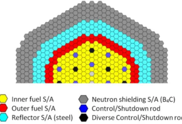
cheap and widely used design and that boron carbide is one of the best neutron absorber, this configuration was justified for ASTRID and adopted for the CFV core design versions v1 and v2. The reduction of to the duct-wall thickness and inter-assemblies gap permitted to increase the number of fuel S/A by 64 between the cores v1 and v2 without impact on the vessel size. At the end of the pre-conceptual design phase (Chenaud et al., 2013), the layout of the CFV v2 core comprised 355 fuel S/A (Fig. 1).
Fig. 1. Layout of ASTRID core CFV v2. 3.2. Design of sub-assemblies
The reflectors S/A for CFV v1 core are made of EM10 steel arranged in a bundle of 19 rods separated by a helical spacer wire. EM10 has been chosen as the material for the hexagonal wrapper tubes of all sub-assemblies in ASTRID. This martensitic 9%Cr-1%Mo stainless steel exhibits excellent dimensional stability under
irradiation (Le Flem et al., 2014). A record dose of 155 dpa was reached on the EM10 wrapper tube during the BOITIX-9 experiment in Phénix, with a very low irradiation swelling. The steel rod’s diameter is 34 mm and the maximum temperature inside the rods was evaluated to 580°C which is acceptable. The surface fraction of EM10 in the S/A is 75%. The expected life-time, defined with respect to the dose criteria, is 24 years for the first ring of reflectors S/A and 60 years for the other rings.
The radial neutron shielding S/A comprise a bundle of 37 pins filled with natural B4C (19.78% of 10B). The
cladding is made of 15-15Ti AIM1 austenitic stainless steel (Le Flem et al., 2014) for standardization with the fuel pins cladding. This special 15%Cr-15%Ni cold-worked austenitic steel demonstrated a low swelling up to high dose rates in Phénix. The pins have a diameter of 24.7 mm and are separated by a 1 mm-diameter helical spacer wire. B4C pellets have a surface fraction of 31% and are confined by a stainless steel shroud. As a
preliminary design, the B4C pins are leaktight and comprises an upper and a lower plenum of 50 cm each. The
helium produced by the 10B(n,α)7Li neutron capture reactions leads to a unacceptable pressure of 150 bars inside the pins over 20 years.
3.3. Performance evaluation
The assessment of the activity concentration in the secondary sodium at full power operation is the result of a detailed calculation scheme implying (Chapoutier et al., 2015):
Core neutron calculations, made with the reference CEA deterministic ERANOS code (Rimpault et al., 2002), for the computation of the 3D-shape distribution of neutrons released from fission,
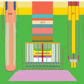
Neutron propagation calculations from the core to IHXs and computation of activation rates in secondary coolant volumes. This step is performed with the stochastic MCNP Monte-Carlo transport code (Brown et al., 2010), using a model with detailed heterogeneous geometries of the core lattice (fuel S/A, reflectors and shielding S/A) and the surrounding components: the diagrid, the ACS, 3 Primary Pumps (PP) and 4 IHXs (Fig. 2).
Fig. 2. MCNP model – Vertical view.
The neutron damages calculated on the diagrid and the ACS were respectively 0.24 and 0.002 dpa which were largely below the objective of 1 dpa. However the secondary sodium activity was calculated at ~1400 Bq/cm3 which was significantly above the target value (10 Bq/cm3). Simulations showed that 60% of this activity level was due to radial neutron leakages, 35% was due to lower axial neutron leakages while only 5% was due to upper axial neutron leakages. It also showed that 38% of the total activity level was generated inside the plenum of the IHX. These results demonstrated the need to optimize the radial and lower shields of the core. Those parametric studies are described in the following section.
4. Parametric studies
Designing ASTRID core shielding consisted in identifying the best arrangement of reflector, moderator and absorber materials in the available space. The global problem is fully three-dimensional because of the specific azimuthal locations of the IHXs in the reactor vessel and their relative elevation as compared to the core source.
At the core level, the neutron shielding located at the top of the fuel sub-assemblies provides neutron absorption in the upper axial direction. Many studies have been made for designing the upper neutron shielding in the fuel S/A (Beck et al., 2017) but those are not discussed here because upper neutron leakages were of a secondary importance. The lower neutron shielding in the fuel S/A is also less of an issue because of the presence of a lower fertile blanket.
However, preliminary simulations (see previous section) showed that lower axial leakages in the radial S/A area contributed for 1/3 in the secondary sodium activation. This was imputed to the presence of lower plenum inside the B4C radial S/A. Further optimisations should thus consist in minimising the plenums height. In the
radial direction, where neutron leakages are preponderant, a thickness of about 2 m remains available from the core boundary to the diagrid outer periphery. Within such a distance up to 7 more rings of radial S/A could be implemented without impact on the vessel size.
The ASTRID core shielding studies are detailed in Chapoutier et al., 2015 and summarized in this section. Parametric and iterative studies have been performed between core and S/A designers to identify an acceptable configuration. The search of the best radial shielding materials, their arrangement in the core, and the shield of the IHX were the aim of these studies.
4.1. Radial S/A materials and arrangement
Regarding materials provided in the radial sub-assemblies, many candidates have been preselected to fulfill the functions of reflection, moderation or absorption. Apart from EM10 steel which was initially considered for reflectors S/A, evaluations were made on: SiC, MgO, MgAl2O3, 11B4C, B4C (10B enriched or not), vanadium
alloy, Hf, Hf11B2 or borated steel.
B4C is obviously the best neutron absorber and benefits from a large feedback in SFR applications as
absorber rods. However, material inventories involved in the shielding zones are potentially significant and cost aspects must be considered in the analysis. Besides neutron performances of each configuration, other criteria were consequently evaluated: behavior under irradiation, life duration, chemical compatibility, safety, maturity levels, availability, washing and manufacturing capability, qualification needs.
Despite a very efficient reflector-moderator effect, 11B4C and Hf11B2 have been finally excluded due to
prohibitive manufacturing costs regarding the enrichment in 11B. Hafnium has been excluded due to a possible large-scale limited availability. Moderation hydride compounds (YH2) have been excluded for safety
consideration (hydrogen risk in accidental conditions).
The reflector function is only required in the radial direction at the fissile core boundary. Considering that ASTRID core does not include any radial fertile blanket there is an incentive to maximize neutron economy. For this purpose SiC, MgO and MgAl2O3 appeared as the best candidates and benefited from R&D done at CEA as
inert matrix for minor actinides transmutation. Regarding the manufacturing and cost points of view, MgO was finally selected as the reflector S/A material in the first rings just surrounding the fissile core.
For the remaining regions, which are radially behind the MgO reflectors S/A, a large number of
configurations have been calculated with the objective of limiting the amount of B4C – especially enriched in 10B
– as much as possible. With the suppression of upper and lower plenums in the radial S/A to reduce axial leakages, MCNP calculations showed that the alternation of moderation and absorption zones provided
satisfactory attenuation factors. Good results were obtained with successive alternations of 3 rings of MgO and 3 rings of natural B4C; this configuration was then selected for the following studies (see section 5). Calculations
exhibited that radial neutron leakages were largely reduced but highlighted that the main contributor to the secondary sodium activity became neutrons leaking axially above the core and bypassing lateral shields. Thus, even with an efficient upper neutron shielding fully made of B4C in the fuel S/A, the secondary sodium activity
reached ~70 Bq/cm3, which represented a reduction by a factor 20 compared to first design, but was still significantly above the target value.
4.2. IHX shielding
Since increasing the distance between the core and the IHXs was not an option regarding the vessel size, it has been proposed to implement neutron shields on the IHXs, especially at the elevations subjected to high neutron flux – not in front of the lateral shielding S/A – i.e. the upper and lower parts. Reactor designers proposed solutions to implement 25 to 50 mm-thick borated steel plates – grade 304B7 with 2% natural boron – to envelop the upper and the lower zones of the heat exchangers. MCNP calculations demonstrated that the IHX shielding decreased the secondary sodium activity by a factor ~10 which permitted to reach the objective of 10 Bq/cm3.
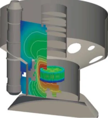
The Fig. 3 shows an overview of the neutron streaming in that configuration. The main contribution at the IHX level is now coming from the axial upper and lower pathways. Compared to these axial pathways, the radial pathways are totally mitigated which demonstrates the good efficiency of the radial shielding.
Fig. 3. MCNP calculation of neutrons streaming from core to IHX. 5. Second configuration – Conceptual design
5.1. Core layout CFV v3 & v4
Parametric studies on radial S/A materials and arrangement (see previous section) finally led to a core layout based on successive alternation of MgO and B4C sub-assemblies providing enhanced radial neutron absorption.
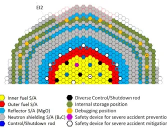
The CFV v3 core architecture (Venard et al., 2015) consists of 180 inner fuel S/A and 108 outer fuel S/A, surrounded by 11 rings of radial S/A: 3 rings of reflectors with MgO, 3 rings of shielding with B4C, 3 rings with
MgO and 2 last rings of shielding with B4C (Fig. 4). The number of radial S/A rings has been increased by 4
compared to previous core CFV v2.
Fig. 4. Radial shielding of ASTRID core CFV v3.
The layout of the CFV v4 core (Venard et al., 2017, Fig. 5) remains the same as the v3 core. Major changes integrated into v4 concern the design of the upper shielding in the fuel S/A – which has been made removable (Beck et al., 2017) – with no significant impact on the core performance levels. About 150 S/A positions are hosted in the radial shielding area to serve as internal fuel storage and debugging purpose. Several configurations of internal storage have been studied; the impact of its presence on the secondary sodium activity is very low (Chapoutier et al., 2015).
Fig. 5. Layout of ASTRID core CFV v4 with internal storage. 5.2. Design of sub-assemblies
5.2.1. Reflectors S/A
In CFV v4 core there are 344 reflectors S/A managed in 5 rings, 3 of them being immediately at the periphery of the fissile core. They comprise a bundle of 19 pins filled with MgO pellets at 96% relative density. The cladding, made of 15-15Ti AIM1 steel, has an outer diameter of 33.6 mm and a thickness of 1 mm. Pins are separated by a 2 mm-diameter helical wire. The surface fraction of MgO is 52% inside the bundle. As MgO does not produce gas under irradiation, pins are leaktight and filled with helium at atmospheric pressure. The other parts of the reflector S/A, such as the wrapper tube, the lifting head and the spike, are similar to those of fuel S/A. The first ring of reflectors S/A adjacent to the fuel S/A are subjected to the highest loadings. Those are maximal for the pin which is closest to the fuel: power dissipation in MgO pellets and dose rate in cladding reach respectively ~8 W/cm3 and ~11 dpa/year at core mid-plane. The loadings decrease exponentially as it goes radially through the pins and they are divided by a factor ~4 for the second ring of reflectors.
Factors limiting the residence lifetime of S/A in the first ring are the dose reached in the AIM1-steel cladding and the bowing of the hexagonal duct caused by the radial dose gradient in two opposite faces. An excessive bowing increases the effort required to extract the S/A from the core during fuel reloading periods, with a risk to exceed the capability of the handling machine. Mechanical simulations performed at the core level showed that the bowing could be inversed by rotating by 180° the sub-assemblies in the first and second rings every 5 and 10 years respectively, then increasing the lifetime. The limitation regarding the dose in the cladding can be managed to extend the residence time by interchanging S/A from the first ring with S/A in the last rings.
Different management scenarios have been evaluated with the objective to perform the maximum of operations every 10 years during the decennial maintenance periods in order to not impact the availability rate of the reactor. Other intermediary operations – every 5 years – are to be performed during the standard fuel reloading periods. Table 1 shows that in any cases S/A of rings #3 to #5 can stay in the reactor during 60 years without any maintenance. The lifetime of first and second rings is limited to 5 and 10 years respectively if there is no specific management (scenario A). A simple rotation by 180° permits to reach 10 and 60 years respectively on rings #1 and #2 (scenario B). A more complex management with rotations and permutations between the rings #1 to #4 can extend the lifetime of ring #1 up to 20 years (scenario C).
Table 1
Lifetime (years) of reflectors S/A as a function of the management scenario. Residence lifetime (EFPY)
Scenario Ring #1 Ring #2 Ring #3 Ring #4 Ring #5
A 5 10 60 60 60
B 10 60 60 60 60
C 20 60 60 60 60
Scenario A No management.
Scenario B Ring #1: rotation by 180° every 5 years. Ring #2: rotation by 180° every 10 years. Rings #3-4-5: no management.
Scenario C Ring #1: rotation by 180° after 5 years and permutation with ring #4 after 10 years. Ring #2: rotation by 180° every 10 years and permutation with ring #3 after 10 years. Rings #5: no management.
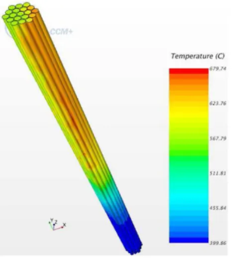
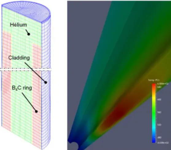
Preliminary thermal-hydraulic calculations have been performed with the STAR-CCM+ CFD code to verify the need of feeding the reflectors S/A with cold sodium flow. In natural convection – without sodium flow – maximum cladding temperatures are above the thermal criteria of 600°C (Fig. 6). Simulation at core mid-plane shows the heterogeneous radial distribution of sodium temperature due to the three adjacent fuel S/A which are colder (Fig. 7). It has been finally found out that the first ring would require a sodium flow of ~0.6 kg/s to respect thermal criteria on claddings, while the others rings could be cooled by natural convection.
Fig. 6. Cladding temperature distribution of MgO-pins bundle – Without sodium flow.
Fig. 7. Sodium temperature distribution in S/A in core mid-plane – Without sodium flow. 5.2.2. Radial shielding S/A
There are 550 shielding S/A in the CFV v4 core which are managed in 5 rings behind the reflectors S/A. They comprise a bundle of 19 pins filled with natural B4C pellets. Parametric studies showed that neutron
leakages could be reduced thanks to the suppression of upper and lower plenums (see section 4). For this purpose B4C pins were made non-leaktight, thus avoiding any excessive pressurization – by allowing helium produced
under irradiation to be continuously released out of the pin – and taking advantage of the higher thermal conductivity in the sodium bond. The height of the B4C column was increased by one meter compared to the
previous leaktight-pin design, reaching about 3.3 m. 5.3. Performance evaluation
Considering the above described radial shielding S/A and providing the IHXs are shielded with borated steel sleeves, the best estimate results from the MCNP calculations were a 24Na activity of ~7.7 Bq/cm3 in the
secondary loops without an internal storage, and ~9 Bq/cm3 with an internal storage as described for CFV v4 core (Fig. 5). These results were compliant with the ASTRID specification but the studies were not finished yet.
If MgO reflector S/A did not show any concern in the preliminary design, two issues have been raised concerning the radial shielding S/A with Na-bonded B4C pins.
These absorber pins comprise a lower and an upper porous vent through which helium is released and sodium flows inside the pins. Due to B4C fragmentation under irradiation, small fragments may plug the
micrometric pores of the vents and hinder pin draining. This is made even more difficult when considering the sub-millimetre cladding-pellet gap inside the pins. Thus it is well-known that the sodium inside the Na-bonded absorber pins cannot be totally removed after draining. Yet this non-negligible amount of Na trapped inside the pins engenders unacceptable safety risks during the S/A washing phases due to possible uncontrolled exothermal sodium-water reactions.
In addition, Na bond favours carbon diffusion from B4C to the cladding and the shroud. The resulting
carburization causes the embrittlement of the steels and limits the life duration of the pins. Experimental feedback in Phénix reactor for Na-bonded pins regarding shroud embrittlement is limited to ~2 years, which is far from the target of 20 years for ASTRID.
Regarding these issues, the conceptual design phase ended in 2015 with the observation that the radial shielding S/A design for CFV v4 core, i.e. with sodium-bonded pins, was not acceptable. It has been decided to pursue studies to make the leaktight-B4C-pins design realistic.
6. Third configuration – Basic design
Conceptual design studies performed on the CFV v4 shielding S/A demonstrated the need to make B4C pins
non-leaktight in the first ring of S/A to avoid any unacceptable pressurization in the pins. It has been shown also that a leaktight-pin design would become realistic as long as neutron captures in B4C – i.e. helium production –
were decreased by a decade.
6.1. Core layout CFV Basic Design
Neutron transport calculations were performed on the core with the objective of reducing by a factor ~10 the neutron captures in the first ring of B4C radial S/A. This objective was reached by adding 2 MgO reflectors rings
between the fuel core and the B4C S/A. The new core configuration was then composed of 5 rings of MgO
reflectors S/A and 6 rings of B4C shielding S/A in which the internal storage is hosted.
A configuration with alternation of 2 B4C rings, 2 MgO rings and 2 B4C rings has also been evaluated but
did not show advantage compared to the configuration with 6 B4C rings.
6.2. Design of sub-assemblies
The design of MgO reflectors S/A remains identical to the one of CFV v4 core (see section 5.2).
The design of shielding S/A relies on a single leaktight cylinder filled with natural B4C annular rings and
helium at atmospheric pressure. The sealed cylinder is made of 3.5 mm-thick 15-15Ti AIM1 cladding, capped by two welded plugs, and inserted inside the hexagonal wrapper tube (Fig. 8). This design confers the advantage, compared to a pins bundle, to arrange a large plenum inside the B4C rings instead of placing it at upper and/or
lower ends. This avoids reduction of absorber column height while increasing the plenum volume. An acceptable B4C surface fraction of 40% is reached. There is no concern about the structural integrity of B4C rings under
thermal and seismic loads, however the rings are provided with an internal shroud to eliminate the risk of fragment falling in the internal plenum. A small plenum is arranged at the top of the sealed cylinder to enable differential dilatation between the B4C column and the cladding. B4C rings density is 80% which can be obtained
by pressureless sintering process in order to minimize manufacturing costs. The other parts of the S/A, such as the wrapper tube with spacer pads, the lifting head and the spike, are similar to those of fuel S/A.
Fig. 8. Basic design of B4C radial shielding S/A. Side view (top) and section view (bottom).
Finite element calculations have been done using the LICOS code (Helfer et al., 2015a) based on the CAST3M solver within the PLEIADES fuel simulation platform (Helfer et al., 2015b). Power dissipation and neutron captures distributions were defined in the B4C column thanks to MCNP transport calculations at the core
level. Helium release was defined on the basis of one He atom produced per one neutron capture, with a conservative ratio of 100% releasing out of B4C. The dose reached in steel structures over 60 years is less than 5
dpa which is negligible regarding swelling. For S/A in the first ring – behind 5 rings of MgO reflectors – the maximum temperature in B4C and the inner pressure reached over 20 years are respectively 650°C and 42 bars
(Fig. 9). These conditions are compatible with criteria on primary and secondary mechanical constraints in the cladding. For S/A in the other rings, loadings decrease rapidly and the design can be extended to 60 years.
Fig. 9. Thermomechanical simulation on B4C sealed cylinder. Temperatures (°C) in B4C rings.
Besides the B4C design which is the reference for shielding S/A, another option with borated steel has been
evaluated. This design consists of 304B7 borated steel hexagonal blocks inserted in a hermetically sealed wrapper tube filled with helium. Although the helium release under irradiation is less than for B4C blocks, a gas
plenum is arranged at the centre of the steel blocks to limit the pressurization in the wrapper tube (Fig. 10). 3D-thermomechanical calculations have been performed with LICOS code for a S/A in the first ring according to the same approach. Results showed that the temperature reached in the borated steel block is 770°C while the pressure in the wrapper tube is 3.5 bar over 20 years (Fig. 11). The end-of-life pressure is acceptable regarding primary constraints and flat-to-flat deformation of the wrapper tube but the temperature reached in the borated steel blocks appears high regarding the hypothesis of a low helium release. According to these results and because of the lack of irradiation feedback as core materials in SFR, and manufacturing questions, this option was not selected.
Fig. 11. Finite element thermomechanical simulation – Temperatures (°C) in borated steel blocks. 6.3. Performance evaluation
A last round of neutron transport calculations was launched with radial shielding sub-assemblies described above – 5 rings with MgO and 6 rings with B4C annular rings – and with borated steel sleeves provided on the
IHXs. The best estimate result for 24Na activity in the secondary loops was ~10 Bq/cm3, compliant with the objective. There was no evidence of neutron streaming inside the B4C rings.
These recent studies showed several ways of optimization regarding the IHX shields and the radial sub-assemblies design. For example, possible increase in MgO and B4C columns height and manufacturing costs
reduction are identified and will be studied during the on-going Basic Design phase. 7. Conclusion
This paper describes the design studies on radial shielding sub-assemblies performed during the last five years to fulfill ASTRID requirement on the secondary sodium activity level. S/A design studies were part of heavy iterative core shielding studies which are summarized.
Six various reflectors and radial shielding S/A designs (steel, MgO, boron carbide pins or rings with helium or sodium bond, and borated steel) have been evaluated in three different core layouts. A strict value analysis process – considering criteria such as neutron shielding performances, life duration, maturity levels, washing and manufacturing capability, or qualification needs – has been followed from the selection of possible solutions to a final consistent design.
The ASTRID specification of 10 Bq/cm3 for 24Na activity in secondary loops is finally reachable with 5 rings of MgO reflectors and 6 rings of B4C radial shielding S/A surrounding the fissile core. It appears now that the
conceptual design of these sub-assemblies is less of an issue. Other requirements such as washing or manufacturing compatibility are met. Management scenarios have been evaluated in order to extend the
residence lifetime in the core while minimising the impact on the reactor availability. Some ways of optimization have been identified and will be studied during the on-going Basic Design phase.
Acknowledgments
The authors wish to thank all the teams involved in studies of the core and shielding S/A design at CEA and AREVA NP for their support.
References
Beck, T. et al., 2017. Pre-conceptual design of ASTRID fuel sub-assemblies. Nucl. Eng. Des. 315, 51-60.
Brown, F. et al., 2010. MCNP5-1.60 released notes. LA-UR-10-06235, Los Alamos National Laboratory, 2010.
Chapoutier, N. et al., 2015. ASTRID core shielding – Design studies and benchmark analysis. In: Proceedings of ICAPP, Paper 15305, Nice, France, May 3-6, 2015.
Chenaud, M.S. et al., 2013. Status of the ASTRID core at the end of the pre-conceptual design phase 1. Nucl. Eng. Technol. 45 (6).
Helfer, T. et al., 2015. LICOS, a fuel performance code for innovative fuel elements or experimental devices design. Nucl. Eng. Des. 294, 117-136.
Helfer, T. et al., 2015. Recent improvements of the thermomechanical modelling in the PLEIADES platform: Applications to the simulation of PWR accidental transient conditions using the Alcyone fuel performance code. In: Workshop NuFuel & MMSNF, Karlsruhe, Germany, November 16-18, 2015.
Le Flem, M. et al., 2014. Status of the french R&D on ASTRID core materials. In: Proceedings of ICAPP, Paper 14117, Charlotte, USA, April 6-9, 2014.
Rimpault, G., et al., 2002. The ERANOS code and data system for fast reactor neutronic analyses. In: Proceedings of PHYSOR, Seoul, Korea, 2002.
Rouault, J. et al., 2015. ASTRID, the SFR GEN IV technology demonstrator project: Where are we, where do we stand for? In: Proceedings of ICAPP, Paper 15439, Nice, France, May 3-6, 2015.
Venard, C. et al., 2015. The ASTRID core at the midterm of the conceptual design phase (AVP2). In: Proceedings of ICAPP, Paper 15275, Nice, France, May 3-6, 2015.
Venard, C. et al., 2017. The ASTRID core at the end of the conceptual design phase. In: Proceedings of FR17, Paper IAEA-CN-245-288, Yekaterinburg, Russia, June 26-29, 2017.
Glossary
ACS: Above Core Structures
ASTRID: Advanced Sodium Technological Reactor for Industrial Demonstration AVP1/2: Conceptual design phase #1/2
CFD: Computational Fluid Dynamics
CFV: Low sodium void core (French acronym) dpa: displacement per atom (dpaNRT)
EFPY: Equivalent Full Power Year EFR: European Fast Reactor IHX: Intermediate Heat Exchanger PP: Primary Pumps
PX: Phénix reactor S/A: Sub-assembly(ies)
SFR: Sodium-cooled Fast Reactor SPX: SuperPhénix reactor