Publisher’s version / Version de l'éditeur:
Vous avez des questions? Nous pouvons vous aider. Pour communiquer directement avec un auteur, consultez la première page de la revue dans laquelle son article a été publié afin de trouver ses coordonnées. Si vous n’arrivez pas à les repérer, communiquez avec nous à [email protected].
Questions? Contact the NRC Publications Archive team at
[email protected]. If you wish to email the authors directly, please see the first page of the publication for their contact information.
https://publications-cnrc.canada.ca/fra/droits
L’accès à ce site Web et l’utilisation de son contenu sont assujettis aux conditions présentées dans le site LISEZ CES CONDITIONS ATTENTIVEMENT AVANT D’UTILISER CE SITE WEB.
17th World Congress on Nondestructive Testing [Proceedings], pp. 1-8, 2008
READ THESE TERMS AND CONDITIONS CAREFULLY BEFORE USING THIS WEBSITE.
https://nrc-publications.canada.ca/eng/copyright
NRC Publications Archive Record / Notice des Archives des publications du CNRC : https://nrc-publications.canada.ca/eng/view/object/?id=fd1e4653-9823-4867-af3a-f91e226015bb https://publications-cnrc.canada.ca/fra/voir/objet/?id=fd1e4653-9823-4867-af3a-f91e226015bb
NRC Publications Archive
Archives des publications du CNRC
This publication could be one of several versions: author’s original, accepted manuscript or the publisher’s version. / La version de cette publication peut être l’une des suivantes : la version prépublication de l’auteur, la version acceptée du manuscrit ou la version de l’éditeur.
Access and use of this website and the material on it are subject to the Terms and Conditions set forth at
High temperature integrated and flexible ultrasonic transducers for
NDT
Kobayashi, Makiko; Jen, Cheng-Kuei; Bussiere, Jean-François; Wu,
Kuo-Ting
17th World Conference on Nondestructive Testing, 25-28 Oct 2008, Shanghai, China
High Temperature Integrated and
Flexible Ultrasonic Transducers for NDT
M. KOBAYASHI
1, C.-K. JEN
1, J.F. BUSSIERE
1and K.-T. WU
21. Industrial Materials Institute, National Research Council Canada, 75 Blvd de Mortagne,
Boucherville, Quebec J4B 6Y4, Canada
2. Department of Electrical and Computer Engineering, McGill University, 3480 University
St., Montreal, Quebec H3A 2A7, Canada
Tel: 450-641-5085; Fax: 450-641-5106
Email: [email protected]
Abstract
Integrated (IUTs) and flexible ultrasonic transducers (FUTs) are presented for NDT at high temperatures. These transducers are made of sol-gel sprayed piezoelectric thick (> 40µm) ceramic films. The ceramic materials are lead-zirconate-titanate, bismuth titanate and lithium niobate which are for thickness measurement up to 150°C, 400°C and 800°C, respectively. The IUT can be also deposited onto one end of a long ultrasonic delay line to perform non-destructive testing at the other end at even higher temperatures. FUTs made of bismuth titanate films onto thin stainless steel foils are also used for thickness measurements at 300°C with a high temperature couplant sandwiched between the FUT and a steel substrate. All experiments at high temperatures were performed in pulse-echo and ultrasonic echoes with signal to noise ratios above 20dB were obtained. The centre operation frequencies of both IUTs and FUTs range from 4.4MHz to 10.7MHz.
Keywords:
High temperature, Integrated ultrasonic transducers, flexible ultrasonic transducers,
NDT
1. Introduction
Ultrasonic techniques employing piezoelectric ultrasonic transducers (UTs) have been widely used to perform non-destructive testing (NDT) on metallic structures such as airframes, engines, pipes, nuclear power plant structural parts, etc because of the subsurface inspection capability, simplicity and cost-effectiveness [1-3]. Many of these applications such as corrosion, erosion, defect detection, etc are carried out at high temperatures (HT). Therefore there is a demand of HTUTs [4-7].
The limitations of the current HTUTs are (1) complicated to be used for curved surfaces, (2) difficult to be used for pulse-echo mode and (4) not efficient to be used for temperature higher than 400°C. In this investigation, sol-gel sprayed thick (>40 µm) piezoelectric ceramic films as HTUTs [8-10] are presented. Piezoelectric powders to be used are lead-zirconate-titanate (PZT), bismuth titanate (BIT) and lithium niobate (LiNbO3) which have Curie temperatures of 350°C, 675°C and 1210°C. One type is that these
films directly deposited onto the parts to be tested are called integrated ultrasonic transducers (IUTs). Such IUTs do not require ultrasonic couplant. Another type is that the substrate of IUTs is thin metal foil such as 35µm thick stainless steel membrane. This type of UT is named as flexible UT (FUT) [11]. FUTs can be made off-line and require ultrasonic couplant to perform the NDT on parts or structures.
Corrosion is a general safety concerning for metallic parts and structures. In particular, stress corrosion cracking, corrosion pitting and exfoliation corrosion are commonly found in aircraft structures
[12,13].
There is a critical need to perform in-situ quantitative thickness measurement to determine the degree of corrosion and provide correlation to component’s residual fatigue life. The objective of this study is to develop HT IUTs and FUTS using the above mentioned piezoelectric ceramics. These IUTs or
FUTs will need to have good ultrasonic performance in pulse-echo mode which only needs one side access so that high thickness measurement accuracy can be obtain at temperatures up to 800°C.
It is also another objective that to fabricate HT IUT onto one end of an ultrasonic delay line [14-16], the probing end (opposite to the IUT end) can perform at temperature even higher than the maximum temperature of the HT IUT (e.g. > 800°C). In certain situations parts or structures for NDT cannot be exposed to high temperature fabricate procedures of the IUT, then HT FUT fabricated off-line can be used for HT NDT except that HT ultrasonic couplant must be used between the FUT and the sample to be tested. The evaluation of the ultrasonic strength of all IUTs and FUTs in this investigation will be based on a commercially available EPOCH (model LT) pulser-receiver device which has a dynamic range of 100dB. This handheld device is commonly used in the NDT industry. The electrical contacts during all measurements were carried out using a spring-loaded two- pin probe.
2. Fabrication and Ultrasonic Performance of IUTs
The sol-gel based sensor fabrication process consists of six main steps [8-10]: (1) preparing high dielectric constant lead-zirconate-titanate (PZT) solution, (2) ball milling of piezoelectric PZT, BIT or LiNbO3 powders to submicron size, (3) sensor spraying using slurries from steps (1) and (2) to produce a
film of thickness between 5 and 20µm, (4) heat treating to produce a solid composite (PZT/PZT, BIT/PZT or LiNbO3/PZT) thin film, (5) corona poling to obtain piezoelectricity, and (6) electrode
painting or spraying for electrical connections. Steps (3) and (4) are used multiple times to produce optimal film thickness for specified ultrasonic operating frequencies. The heat treatments in step (4) are different for different ceramic powders. Silver or platinum paste was used to fabricate top electrodes. Such electrode fabrication approach enables to achieve desired sensor array configurations easily and economically. In this study longitudinal ultrasonic wave transducers are used. The dielectric constant is calculated using the measured capacitance by an impedance analyzer.
2.1 IUT made of PZT/PZT composite film
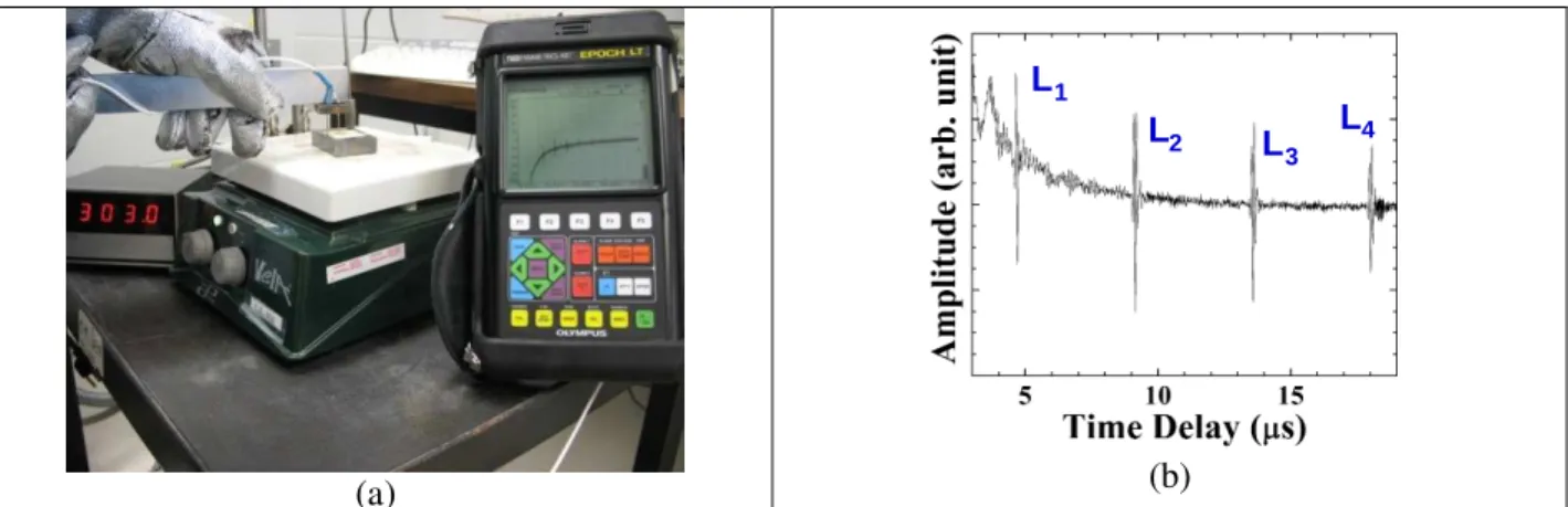
Fig.1a shows an IUT made of 42µm thick PZT/PZT composite film and deposited onto a 12.7mm thick steel plate and measured by a handheld EPOCH LT pulser-receiver at 163°C. The highest heat treatment temperature for this sample in the furnace was 650°C. The diameter of the top silver paste electrode of this IUT is 6.0mm. The measured ultrasonic data in pulse-echo mode at 150°C is presented in Fig.1b, where Ln is the nth round trip L echo through the plate thickness. The SNR of the L1 echo at
150°C is 28dB. In the measurement at 163°C shown in Fig.1a 19dB gain out of the available 100dB was used for producing the L1 echo reflected from the bottom of the plate. This result indicates that this L
wave IUT is efficient.
(a)
L1
L2 L
3 L4
(b)
Fig.1 (a) Measurement setup for an IUT made of PZT/PZT composite film at 163°C using an EPOCH LT; (b) Measured ultrasonic data in pulse-echo mode at 150°C.
At room temperature only 10dB gain was used to produce the same L1 echo signal strength. At 150°C
the centre frequency and the 6dB bandwidth are 6.0MHz and 3.3MHz respectively. The sign It is noted that PZT/PZT IUT can function at least up to 200°C. Three hundred and seventy five thermal cycles of such IUTs have been carried out. Each thermal cycle consisted of 5-10 minutes heating from room temperature to 150°C, 30 minutes remaining at 150°C and 10 to 30 minutes cooling from 150°C to room temperature. There is no any deterioration of the ultrasonic performance after these cycles. This IUT is normally used at temperature up to 150°C and its relative dielectric constant is 80.
2.2 IUT made of BIT/PZT composite film
An IUT made of 79µm thick BIT/PZT composite film and deposited onto a 12.7mm thick steel plate and measured by the EPOCH device at 400°C is shown in Fig.2a. The highest heat treatment temperature for this sample in the furnace was 650°C.The dimension of the top rectangular silver paste electrode of this IUT is 8.0mm by 8.0mm. At 400°C 47dB gain out of the available 100 dB was used for producing the L1 echo reflected from the end of the plate. The SNR of the L1 echo at 400°C is 23dB.The measured
ultrasonic data at 400°C in pulse-echo mode is presented in Fig.2b. It indicates that this L wave IUT is capable at 400°C. At room temperature 40dB gain was used to obtain the same L1 echo signal strength. At
400°C the centre frequency and the 6dB bandwidth are 5.5MHz and 4.6MHz respectively. It is noted that BIT/PZT IUT can function at least up to 500°C. Three hundred and seventy five thermal cycles of such IUTs have been carried out. Each thermal cycle consisted of 15 minutes heating from room temperature to 400°C, 30 minutes remaining at 400°C and 20 to 45 minutes cooling from 400°C to room temperature. There is no any deterioration of the ultrasonic performance. This IUT is normally used at temperature up to 450°C and its relative dielectric constant is 25.
(a) L1 L 2 L3 L 4 (b)
Fig.2 (a) Measurement setup for an IUT made of BIT/PZT composite film at 400°C using an EPOCH LT; (b) Measured ultrasonic data in pulse-echo mode at 400°C.
2.3 IUT made of LiNbO
3/PZT composite film
Fig.3a shows an IUT made of 125µm thick LiNbO3/PZT composite film and deposited onto a
25.4mm diameter 26.3mm thick titanium rod and measured by the EPOCH device at room temperature. The titanium rod is chosen because of less oxidation at temperature higher than 500°C. The heat treatment procedures used here are different from the one used in Sections 2.1 and 2.2. A special designed induction heating device was developed to perform the local heat treatment. The maximum temperature is higher than 700°C. The diameter of the square top platinum paste electrode of this IUT is 10mm by 10mm. At room temperature 50dB gain out of the available 100dB was used for producing the L1 echo reflected
from the end of the rod. The measured ultrasonic data at 800°C in pulse-echo mode is shown in Fig.3b. It is demonstrated that this L wave IUT may be sufficient for many applications. At 800°C 90dB gain was used to produce the same L1 echo signal strength and the centre frequency and the 6dB bandwidth were
4.4MHz and 3.2MHz, respectively. The SNR of the L1 echo at 800°C is 20.3dB. It is noted that
thermal cycles of such IUTs from room temperature to 800°C using gas torch heating method. Each thermal cycle tool about the total duration of 40 minutes. There is no any deterioration of the ultrasonic performance after five cycles.
(a)
L1
L2
(b)
Fig.3 (a) Measurement setup for an IUT made of LiNbO3/PZT composite film at room temperature using an
EPOCH LT; (b) Measured ultrasonic data in pulse-echo mode at 800°C.
2.4 IUT deposited onto a clad buffer rod
As mentioned in the Introduction another objective of this study is to fabricate HT IUT onto one end of a long ultrasonic delay line (or buffer rod) [14-16], the probing end (opposite to the IUT end) can perform NDT at temperature even higher than the maximum temperature of the HT IUT (e.g. > 800°C). Fig.4a presents IUTs made of ~106µm thick PZT/PZT composite film and deposited onto two clad steel buffer rods [15,16] measured by an EPOCH LT system. The temperature at the IUT end is 151°C and that at the other rod end is 182°C. The heat treatment procedures used here are also different from the one used in Sections 2.1 and 2.2. A special designed induction heating device was developed to perform the local heat treatment and the maximum temperature is higher than 700°C.
(a) (b)
Fig.4 Measurement setup for an IUT made of PZT/PZT composite film at room temperature using an EPOCH The clad steel buffer rod consists of a steel core and a stainless steel (SS) cladding made by thermal spray process. As shown in Fig.4b the clad steel rod shown on the left has a core diameter of 12.7mm and another shown on the right has a core diameter of 25.4mm. Both rods have ~1mm thick SS cladding and a length of 102mm. The clad steel rod is chosen because of their high signal to noise ratio (SNR), in particular, in pulse-echo mode which provide advantages for in-line ultrasonic monitoring of industrial material manufacturing such as polymer extrusion [17] and molten metal processes [16]. The diameter of the silver paste top electrode of the IUT is 6.5mm and 7.0mm, respectively, on the small and large diameter. When the IUTs at 151°C only 10dB and 20dB gain, respectively, out of the available 100dB were used for the small and diameter clad steel rods for producing the L1 echo reflected from the end of the rod. Ln
the measured temperature was 182°C which is 31°C higher than 151°C. To produce the same L1 echo
signal strength for the small and large diameter clad buffer rod at room temperature 5dB and 15dB gains, respectively, were used. The relative dielectric constants of the IUT for small and large diameter clad rod are 290 and 190, respectively. The difference between the relative dielectric constants of the PZT/PZT deposited on the clad rods shown in Fig.4b and that of the steel plate shown in Fig.1b comes from the different heat treatment procedures. The measured ultrasonic data at 150°C in pulse-echo mode for the small and large diameter rods shown in Fig.4b are shown in Fig.5a and 5b, respectively. At 150°C the centre frequency and the 6dB bandwidth of the L1 echo were 7.0MHz and 5.9MHz, respectively for the
small diameter rod and 6.8MHz and 3.7MHz, respectively for the large diameter rod. The SNRs of the L1
echoes for IUTs at 150°C are 26dB and 30dB, respectively, for the small and large diameter clad rods. In Fig.5b the amplitude of L3 echo is larger than that of L2 echo is due to the diffraction effect. Figs.5a and
5b confirm that PZT/PZT IUTs have excellent performance at 150°C. It is expected that these IUTs deposited onto these clad steel rods will perform the same during thermal cycles as the BIT/PZT film coated onto steel substrate as mentioned in Section 2.1.
L1 L2 L 3 L4 L 5 L6 (a) L1 L2 L3 L4 L5 L6 (b)
Fig.5 Measured ultrasonic data of IUT at 150°C in pulse-echo mode for (a) small and (b) large diameter clad steel rod shown in Fig.4b.
3. Fabrication and Ultrasonic Performance of FUTs
The other type of sensor developed is the HT FUT which can be made off-line. Since in certain situations parts or structures for NDT cannot be exposed to high temperature fabricate procedures of the IUT, then such HT FUT may be used for HT NDT. In this situation HT ultrasonic couplant must be used between the FUT and the sample to be tested. FUT made of PZT/PZT composite film has been reported in reference [18]. Here only the BIT/PZT composite film made onto SS foils is presented. The fabrication procedure is the same as those described for BIT/PZT ceramic powders in Section 2. Many FUTs using PVDF [19] and polymer composites [20, 21] were reported, however, they may not be effectively used at temperatures higher than 150°C. The FUT made of BIT/PZT film coated onto a 35µm thick SS foil has been examined after one thousand times bending test with a curvature of 25mm diameter. There is no observable damage both in visual appearance and ultrasonic performance. Such FUT is bonded onto a 12.7mm thick steel substrate using a metallic adhesive (from Cotronics Corp., Brooklyn, NY.) cured at 300°C for two hours. Fig.6a shows the measurement setup at 300°C using the Epoch device and the measured ultrasonic data is presented in Fig.6b. The centre frequency and the 6dB bandwidth of the L1
echo at 300°C were 10.7MHz and 8.2MHz, respectively. The SNR of the L1 echo is 22dB. The 300°C test
temperature is limited to the high temperature bonding material used. One desires such bonding material which not only provides good bonding between the FUT and the surface of the sample to be tested at high temperatures, but also do not induce high spurious signals. Fig.6b demonstrates the capability of FUT for NDT at 300°C. It is noted that such FUT itself can function at least up to 500°C and its relative dielectric constant is 13. It is expected that these FUTs made of BIT/PZT film and deposited onto stainless steel foil will perform the same during thermal cycles as the BIT/PZT film coated onto steel substrate mentioned in Section 2.1.
(a) L1 L2 L 3 L4 (b)
Fig.6 (a) Measurement setup for a FUT made of BIT/PZT composite film deposited onto a 35µm thick SS foil and bonded onto a 12.7mm thick steel subtracted using an EPOCH; (b) Measured ultrasonic data in pulse-echo mode at 300°C.
4. Thickness Measurement accuracy estimation
As mentioned in Introduction corrosion monitoring is a critical demand for NDT. Here the thickness measurement accuracy at high temperature is presented. Only one example using the two clad steel rods shown in Figa.4a and 4b is given. The temperature at the IUT side is 151°C and that at the other end of the rod is 182°C. Assuming these two clad rods are under a constant temperature of 150°C equation (1) (Equation 19 in reference [22]) is used here for the estimation of the measurement accuracy for the time delay and then length of the clad steel rod using IUTs, where f0 is the center frequency, T the time
window length for the selection of e.g. L1 and L2 echoes for the cross correlation, B the fractional bandwidth of the signal (the ratio of the signal bandwidth over f0), ρ the correlation coefficient used in
cross correlation, SNR1 and SNR2 the SNR of the 1 st
echo (e.g. L1 in Figs.5a and 5b for small and large
clad rod) and 2nd echo (e.g. L2 in Figs.5a and 5b for small and large clad rod), respectively, σ (∆t - ∆t’) the
standard deviation of the measured time delay (∆t the true time delay; ∆t’ the estimated time delay), and VL (5884m/s) the measured longitudinal velocity in the steel core. The estimated rod length measurement
accuracies (assuming under the constant temperature of 150°C) for small and large clad steel rods with a length of 102mm using the above parameters given in Table 1 are 27µm and 35µm, respectively.
(
)
(
)
−
+
+
+
≥
∆
−
∆
1
1
1
1
1
1
12
2
3
'
2 2 2 1 2 3 2 3 0T
B
B
SNR
SNR
f
t
t
ρ
π
σ
(1)Table 1 Parameters for Equation (1) Parameters Small dia. Buffer
Rod @ 150°C
Large dia. Buffer Rod @ 150°C ƒ0 7MHz 6.8MHz T 0.6µs 0.6µs B 5.9/7 3.7/6.8 ρ 0.68 0.7 SNR1 26dB 30dB SNR2 19dB 25dB
)
(
∆
t
−
∆
t
)
σ
9.0ns 11.7ns VL 5884m/s 5884m/s Thickness accuracy 27µm 35µm5. Conclusions
Integrated ultrasonic transducers (IUTs) made of PZT/PZT, BIT/PZT and LiNbO3 piezoelectric
ceramic composite films are presented for thickness measurement at temperatures up to 150°C, 400°C and 800°C respectively. These films ranging from 42µm to 125µm were made by a sol-gel sprayed technique. No couplant is required for IUTs to carry out NDT. These IUTs can be also deposited onto one end of a long ultrasonic delay line to perform NDT at the other end at even higher temperatures (e.g. >800°C). In certain situations parts or structures for NDT cannot be exposed to high temperature fabricate procedures of the IUT, then HT FUT fabricated off-line can be used for HT NDT except that HT ultrasonic couplant must be used between the FUT and the sample to be tested. A FUT made of BIT/PZT film coated onto a 35µm thick SS foil was bonded to a steel plate using a HT metallic adhesive and ultrasonic measurement was performed up to 300°C. All ultrasonic measurements at high temperatures were carried out in pulse-echo mode and ultrasonic signals of SNR above 20dB were obtained. The centre frequencies of these IUTs and FUTs range from 4.4MHz to 10.7MHz. The evaluation of the ultrasonic strength of all IUTs and FUTs in this investigation was based on a commercially available handheld EPOCH LT pulser-receiver device which has a dynamic range of 100dB and is commonly used in the NDT industry. Using Equation 1 (Equation 19 in reference [21]) the estimated rod length measurement accuracies (assuming under a constant temperature of 150°C) for small and large clad steel rods shown in Fig.4b with a length of 102mm using the parameters given in Table 1 are 27µm and 35µm, respectively.
Acknowledgement
Financial support for K.-T. Wu from Natural Sciences and Engineering Research Council of Canada is acknowledged.
References
[1] J. Krautkrämer and H. Krautkrämer, Ultrasonic Testing of Materials, Springer-Verlag, Berlin, 1990.. [2] A.S. Birks, R.E. Green, Jr. and P. McIntire, P. ed., Nondestructive Testing Handbook, 2nd Ed., vol.7,
Ultrasonic Testing, ASNT (1991).
[3] J.B. Ihn and F.-K. Chang, Ultrasonic Nondestructive Evaluation Engineering and Biological Material Characterization, edited by T. Kundu, Chap.9, CRC Press, New York (2004).
[4] T. Arakawa, K. Yoshikawa, S. Chiba, K. Muto and Y. Atsuta, “Applications of brazed-type ultrasonic probes for high and low temperatures uses,” Nondestr. Test. Eval., vol. 7, pp. 263-72, 1992
[5] A.H. Mrasek, D. Gohlke, K. Matthies and E. Neumann, “High temperature ultrasonic transducers,” NDTnet, vol. 1, no. 9, pp. 1-10, 1996
[6] S.P. Kelly, I. Atkinson, C. Gregory and K.J. Kirk, “On-line ultrasonic inspection at elevated temperatures”, Proc. IEEE Ultrasonics Symp., pp.904-908, 2007.
[7] P. Kazys, A. Voleisis, R. Sliteris, B. Voleisiene, L. Mazeika and H.A. Abderrahim, “Research and development of radiation resistant ultrasonic sensors for quasi-image forming systems in a liquid lead-bismuth”, Ultragarsas (Ultasound), vol.62, pp.7-15, 2008.
[8] D. Barrow, T.E. Petroff, R.P. Tandon and M. Sayer, “Chracterization of thick lead-zirconate titanate films fabricated using a new sol gel process” J. Apply. Phys., vol.81, pp.876-881, 1997.
[9] M. Kobayashi and C.-K. Jen, “Piezoelectric thick bismuth titanate/PZT composite film transducers for smart NDE of metals”, Smart Materials and Structures, vol.13, 951-956 (2004).
[10] M. Kobayashi, C.-K. Jen, Y. Ono and J.-F. Moisan, “Integrated high temperature ultrasonic transducers for NDT of metals and industrial process monitoring”, CINDE Journal, vol.26, 5-10 (2005).
[11] M. Kobayashi, C.-K. Jen, and D. Lévesque, “Flexible ultrasonic transducers,” IEEE Trans. Ultrason. Ferroelect. Freq. Contr., vol. 53, pp. 1478-1486, 2006.
[12] E.V. Abolikhina and A.G. Molyar, "Corrosion of aircraft structures made of aluminum alloys", Materials Science, vol.39, pp.889-894, 2003.
[13] M. Mrad, Z. Liu, M. Kobayashi, M. Liao and C.-K. Jen, “Exfoliation detection using structurally integrated piezoelectric ultrasonic transducers”, Insight - NDT & Condition Monitoring, J. the British Inst. of NDT, vol.48, pp.738-742., 2006.
[14] L.C. Lynnworth, Ultrasonic Measurements for Process Control, New York: Academic Press, 1989.
[15] C.-K. Jen, J.-G. Legoux, and L. Parent, “Experimental evaluation of clad metallic buffer rods for high temperature ultrasonic measurements,” NDT & E Int., vol. 33, pp. 145-153, 2000.
[16] Y. Ono, J.-F. Moisan and C.-K. Jen, “Ultrasonic techniques for imaging and measurements in molten aluminum”, IEEE Trans. UFFC, pp.1711-1721, 2003.
[17] Z. Sun, C.-K. Jen, C.-K. Shih and D. Denelsbeck, “Application of ultrasound in the determination of fundamental polymer extrusion performance: residence time distribution measurement”, Polymer Eng. and Science, vol.43, pp.102-111, Jan. 2003.
[18] M. Kobayashi, C.-K. Jen and D. Lévesque, “Flexible ultrasonic transducers ,” IEEE Trans. UFFC, vol.53, pp.1478-1485, 2006.
[19] D.H. Wang, and S.L. Huang, “Health monitoring and diagnosis for flexible structures with PVDF piezoelectric film sensor array”, J. Intelligent Material Systems and Structures, vol.11, pp. 482-491, 2000. [20] T. F. McNulty, V. F. Janas, A. Safari, R. L. Loh, and R. B. Cass, “Novel processing of 1-3 piezoelectric
ceramic/polymer composites for transducer applications”, J. Am. Ceram. Soc., vol. 78, pp. 2913-2916, 1995. [21] A. C. S. Parr, R. L. O’leary and G. Hayward, “Improving the thermal stability of 1-3 piezoelectric composite
transducers”, IEEE Trans. Ultrason., Ferroelect., Freq. Contr., vol. 52, pp. 550-563, 2005.
[22] W.F. Walker and G.E. Trahey, “A fundamental limit on delay estimation using partially correlated speckle signals”, IEEE Trans. UFFC, vol.42, pp.301-308, 1995.