Publisher’s version / Version de l'éditeur:
Journal of Dynamic Systems, Measurement, and Control, 133, 1, pp.
011007-011013, 2011-01-01
READ THESE TERMS AND CONDITIONS CAREFULLY BEFORE USING THIS WEBSITE. https://nrc-publications.canada.ca/eng/copyright
Vous avez des questions? Nous pouvons vous aider. Pour communiquer directement avec un auteur, consultez la première page de la revue dans laquelle son article a été publié afin de trouver ses coordonnées. Si vous n’arrivez pas à les repérer, communiquez avec nous à [email protected].
Questions? Contact the NRC Publications Archive team at
[email protected]. If you wish to email the authors directly, please see the first page of the publication for their contact information.
NRC Publications Archive
Archives des publications du CNRC
This publication could be one of several versions: author’s original, accepted manuscript or the publisher’s version. / La version de cette publication peut être l’une des suivantes : la version prépublication de l’auteur, la version acceptée du manuscrit ou la version de l’éditeur.
For the publisher’s version, please access the DOI link below./ Pour consulter la version de l’éditeur, utilisez le lien DOI ci-dessous.
https://doi.org/10.1115/1.4002717
Access and use of this website and the material on it are subject to the Terms and Conditions set forth at
Contrapropagating Ultrasonic Flowmeter Using Clad Buffer Rods for
High Temperature measurement
Franca, D. R.; Jen, C.-K.; Ono, Y.
https://publications-cnrc.canada.ca/fra/droits
L’accès à ce site Web et l’utilisation de son contenu sont assujettis aux conditions présentées dans le site LISEZ CES CONDITIONS ATTENTIVEMENT AVANT D’UTILISER CE SITE WEB.
NRC Publications Record / Notice d'Archives des publications de CNRC:
https://nrc-publications.canada.ca/eng/view/object/?id=b1fac29a-fcb1-4bef-a1e7-7f3bcff9b776
https://publications-cnrc.canada.ca/fra/voir/objet/?id=b1fac29a-fcb1-4bef-a1e7-7f3bcff9b776
D. R. França
1Department of Electrical Engineering, McGill University, Montréal, QC, H3A 2A7, Canada e-mail: [email protected]
C.-K. Jen
Y. Ono
2Industrial Materials Institute, National Research Council of Canada, Boucherville, QC, J4B 6Y4, Canada
Contrapropagating Ultrasonic
Flowmeter Using Clad Buffer
Rods for High Temperature
Measurements
This work proposes clad buffer rods driven by shear transducers as the main building block of contrapropagating ultrasonic flowmeters for high temperature application. It is demonstrated that the superior signal-to-noise ratio exhibited by clad buffer rods (com-pared with the reported nonclad counterparts) improves precision in transit time mea-surements, leading to more accurate flow speed determination. In addition, it is shown that clad buffer rods generate specific ultrasonic signals for temperature calibration of flowmeters, allowing temperature variation while still measuring accurately the flow speed. On the basis of these experimental results, a contrapropagating ultrasonic flow-meter was designed and installed in a heater machine for flow speed measurements of hot oil at temperatures near 130 ° C. For a temperature variation of 3 ° C, the difference between upstream and downstream ultrasonic transit times, which is proportional to the flow speed at a given temperature, was measured within 1 ns accuracy.
关DOI: 10.1115/1.4002717兴
Keywords: high temperature ultrasonic measurement, contrapropagating flowmeter, clad buffer rods, water flow speed, oil flow speed
1 Introduction
The determination of the liquid flow speed is important for process optimization and control 关1兴. Among all available tech-niques for liquid flow evaluation, ultrasound is advantageous ow-ing to nonintrusiveness, applicability to a large class of materials, robustness, and low cost. In fact, ultrasonic inspection of liquid flow at room temperature is a well-established technique 关2兴. However, several industrial processes, such as polymer extrusion, polymer injection molding, and metal die casting, demand high temperature flowmeter systems for in-line monitoring and control of the melt flow speed. The difficulties encountered by ultrasonic measurement of flow speed and other processes at elevated tem-peratures are related to the Curie point of the ultrasonic transducer 共UT兲 piezoelement, disbonding between the electrode and the ep-oxy backing material, and ultrasonic couplant 关3兴. These draw-backs may be overcome if a suitable buffer rod is interposed be-tween the UT and the process liquid. The typical problem of using buffer rods is the appearance of spurious signals due to dispersion, multipaths, mode conversion, and beam spread 共diffraction loss兲 关4兴. Thus, new materials and buffer rod configurations have been developed recently in order to reduce spurious signals and allow flow speed measurements at high temperatures 关3兴. In these works, an ultrasonic contrapropagating flowmeter was designed employing a hockey stick buffer rod with superior waveguidance just for shear waves. This novel configuration could then success-fully generate longitudinal waves for sensing the liquid flow. However, no attempts have been reported to cancel out the effect of temperature variation in flow measurement. Due to the rapid
temperature variation that the melt flow of industrial processes may undergo, there is an urgent need of developing sensors and techniques immune to temperature variation.
The concept of clad buffer rods共CBRs兲 for ultrasonic monitor-ing of materials and processes have been reported in several ap-plications关5–16兴, and owing to certain advantages 共superior wave guidance, robustness, machinability, and capability to stand high temperature and pressure兲 关17兴, their performance for flow speed measurements at high temperature is now investigated.
In this contribution, we intend to demonstrate that in the stan-dard contrapropagating ultrasonic flowmeters, CBRs exhibit supe-rior signal-to-noise ratio共SNR兲 compared with the reported non-clad rods in through-transmission mode. A high SNR is desirable for more accurate evaluation of flow speeds 关18兴. In addition, specific ultrasonic signals in CBRs can be used for temperature calibration of flowmeters. Such a feature, which is explored for the first time herein, affords temperature variation while still mea-suring accurately flow speeds.
2 Theoretical Background
2.1 Contrapropagating Ultrasonic Flowmeter. In
contra-propagating ultrasonic flowmeters flow speed is obtained by mea-suring, over the same path, the time difference between two ultra-sonic waves traveling downstream and upstream 关19兴. The acoustic waves can be transmitted simultaneously, but typically they are alternated in order to avoid interference between them 关20,21兴. In terms of flowmeter realization, ultrasonic sensors are placed either on opposite facing surfaces or on the same side. Here, we focus on the latter configuration for two basic reasons: It can be mounted on duct surfaces with limited access, and it also enlarges the acoustic travel time difference inside the flow, which enhances resolution in time-domain measurements. In this case, downstream共td兲 and upstream 共tu兲 travel times are found by
vec-tor operation关22兴,
td=
L2+ 4D2
c
冑
L2+ 4D2+ vL 共1兲1Corresponding author. Present address: Department of Electrical Engineering,
Faculty of Technology, University of Brasilia, Brasilia, DF 70919-970, Brazil.
2Present address: Department of Systems and Computer Engineering, Carleton
University, 1125 Colonel By Drive, Ottawa, ON, K1S 5B6, Canada.
Contributed by the Dynamic Systems Division of ASME for publication in the JOURNAL OFDYNAMICSYSTEMS, MEASUREMENT,ANDCONTROL. Manuscript received October 14, 2009; final manuscript received July 26, 2010; published online November 29, 2010. Assoc. Editor: Guoming George Zhu.
tu=
L2+ 4D2
c
冑
L2+ 4D2−vL 共2兲 where L is the axial interaction length between ultrasonic beams,D is the distance perpendicular to the axis between ultrasonic beams, c is the ultrasonic velocity in the fluid, and v is the average flow speed along the path, as shown in Fig. 1. Indeed, if the ultrasonic velocity c were known accurately enough or remained constant, the average flow speed v could be determined by trans-mission in one direction only 共using either Eq. 共1兲 or Eq. 共2兲兲, similar to what is normally done by the beam deflection method 关20兴. For most flowing liquids, however, c is usually 300–700 times larger than v. Therefore, if the fractional uncertainty in c is not exceedingly small, it is not possible to measure v to 1% or better unless transmission in both directions共i.e., contrapropaga-tion兲 is used to cancel c out 关20兴. Such an important feature of the contrapropagation approach is better appreciated by assuming that
cis invariant during measurements of tdand tu. Hence, c can be
eliminated from Eqs.共1兲 and 共2兲 to yield
v= L2+ 4D2 2L
冉
1 td −1 tu冊
共3兲 Equation共3兲 indicates that the average flow speed is a function of downstream and upstream acoustic travel times and duct geom-etry. Furthermore, it is no longer dependent upon ultrasonic ve-locity c, justifying why the contrapropagation method is by far the main flowmeter technique applied in industrial environments关19兴. It is always desirable that during flow measurement the sensor does not disturb the interrogated flow at all. In the contrapropaga-tion method, this can be achieved by means of different installa-tions of buffer rods and UTs over the duct, being the weld-on, weld-in, and clamped-on configurations the most popular 关20兴. For industrial fluids subjected to severe conditions of temperature and pressure, those techniques are safe and effective. Whenever allowed, the weld-in configuration is the simplest one to analyze for acoustic wave propagation is limited to the buffer rod and fluid only. Weld-on and clamped-on versions are more complex be-cause the duct is encompassed by the buffer rod and fluid, requir-ing knowledge about material properties and thickness of the duct wall for proper flowmeter design. Besides, the wall surface may also complicate the acoustic coupling to the fluid. These reasons suggest the weld-in type as the one to be analyzed and imple-mented in this work. Such an approach eliminates the coupling problem by setting the buffer rod probing end flush to the inner surface of a rectangular duct wall.Although two distinct sources, namely, longitudinal and shear wave UTs, can be used in connection with chamfered buffer rods to generate the sensing signals of contrapropagating ultrasonic flowmeters, only longitudinal waves are transmitted through the liquid since fluids in general do not support shear motion. The reason shear waves, under certain conditions such as polarization and incidence angle, can generate longitudinal modes at the
inter-face of two different media is explained by the mode conversion property of the oblique incidence关23,24兴. To introduce a few key concepts on contrapropagating ultrasonic flowmeters design, let us estimate the angle at which the ultrasonic waves propagating in a chamfered buffer rod enter the liquid. For steel CBRs, the longi-tudinal wave velocity in the core is about 6000 m/s at 25° C, and the shear wave velocity is about 3300 m/s关19兴. At high tempera-ture, e.g., 200° C, these values are reduced a few percent 共less than 5%兲 关19兴. For simplicity, the velocity variation will be ne-glected in this first calculation. In hot water at 200° C, the longi-tudinal wave velocity is further reduced to about 1000 m/s关18兴. Assuming 40 deg incidence angle from steel to water at 200° C, the angle of refraction is calculated according to Snell’s law 关22,23兴. If the longitudinal mode is transmitted, the angle of re-fraction in water is found to be about 6.1 deg. Instead, if the shear mode is chosen, the refracted angle becomes about 11.2 deg. Thus, for the same angle of incidence and propagation media, the shear mode incidence results in a larger angle of refraction than longitudinal. Consequently, the propagation path in water and the corresponding transit time difference ⌬t between upstream and downstream transmissions are also enlarged. To put it in a quan-titative way, we subtract Eq.共2兲 from Eq. 共1兲 and assume c Ⰷ v to obtain
⌬t = tu− td⬇ 2共v/c
2
兲L = 4共v/c2
兲D tan r⬘ 共4兲
where r
⬘
is the angle of refraction in water共to the normal of the surface兲, as shown in Fig. 1. In this example, therefore, the transit time difference measured by employing shear UTs is 1.8 times greater than that measured by longitudinal UTs. Clearly, shear UTs are preferable over longitudinal ones for the weld-in contra-propagating flowmeter proposed herein: The resolution in time difference to be measured is increased about 80% as well as the axial interaction length L = 2D tan r⬘
between transmitter and re-ceiver probes. Since UTs cannot be scaled down at will, the latter feature may be an extra advantage in some specific applications. Hence, the ultrasonic flowmeter to be implemented and tested in this work is illustrated in Fig. 1, with shear UTs playing the role of both transmitter and receiver.3 Design of a Contrapropagating Ultrasonic Flowme-ter With Clad Buffer Rods
Before attempting liquid flow measurements at high tempera-ture, the performance of CBRs as part of a contrapropagating flowmeter should be assessed. For this purpose, water flow at constant room temperature 共the simplest alternative兲 is selected for initial tests. It has been seen that if the temperature is kept constant or varies slightly over the period in which ultrasonic signals are acquired, the contrapropagating approach is convenient for measuring flow speeds because it is not necessary to know the ultrasonic velocity in the liquid medium. In this work, however, we will make use of Eq.共4兲 as the ultrasonic velocity in water is a well-known parameter关19,20兴. Its advantage is that one needs to measure only the difference in transit times, rather than their ab-solute values. Thus, characterization of the CBRs is carried out in an immersible water tank, which exhibits high thermal capacity.
As the first design criterion for the flowmeter configuration of Fig. 1, a proper angle for the CBRs must be decided. We chose 40 deg incidence, corresponding theoretically to approximately 94% of the maximum coupled energy between probes. Detailed analy-sis can be found in the literature关25,26兴.
3.1 Comparison Between Clad Steel Buffer Rods and Non-clad Buffer Rods for Contrapropagating Ultrasonic Flowme-ter Design. Cross-correlation is a well-known technique for
mea-suring downstream and upstream transit times in contrapropagating ultrasonic flowmeters 关18兴. Accurate transit time measurements require that spurious noises in the buffer rod do not interfere with the desired ultrasonic signals. It has been reported that steel CBRs are superior to nonclad counterparts for
Fig. 1 Weld-in contrapropagating ultrasonic flowmeter. Shear wave UTs are used to transmit and receive ultrasonic pulses.
wave guidance in pulse-echo mode 关17兴, leading to high SNR 共e.g., SNRⱖ 35 dB兲. Here, our aim is to verify, in through-transmission mode, the SNR superiority of CBRs over nonclad rods for use in contrapropagating flowmeters.
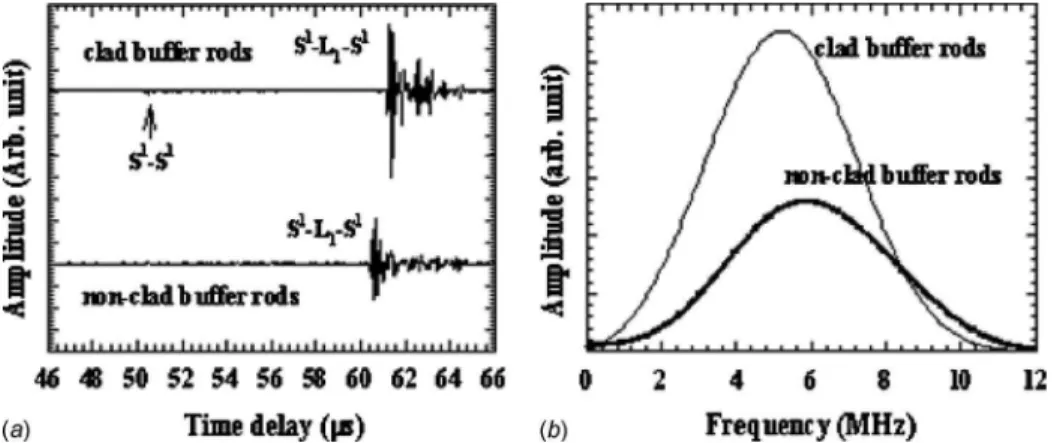
Figure 2 shows steel buffer rods selected for this comparison. One pair共at the left兲 is clad by the thermal spray technique 关17兴, while another pair is nonclad rods. The cladding material is stain-less steel. They have approximately the same length, and each of their probing ends is cut at the same angle of 40 deg. Commercial 5 MHz shear UTs共6.35 mm element diameter兲 attached to the flat end of the buffer rods and operated in through-transmission mode were used for signal generation and detection. Each pair of steel CBRs and nonclad buffer rods were aligned with respect to a steel plate reflector immersed in water, lying 1 cm from the probing end surfaces, as illustrated in Fig. 3. Signals acquired for each con-figuration and frequency spectra of the S1− L1− S1echo共the one
that travels in the transmitter rod, water, and receiver rod兲 are shown in Fig. 4. It is noted that the signal amplitude for the case of CBRs is 6 dB stronger than that obtained from nonclad rods. The superior SNR of CBRs compared with the nonclad rods is expected to improve precision in transit time measurements by the cross-correlation technique, leading to more accurate flow speed determination. In addition, detection of the S1− S1echo is possible only with CBRs. The explanation and application of the S1− S1
echo are given later in this paper. Here, it can be said that the
S1− L
1− S1echo is used to sense flows in contrapropagating
flow-meters.
4 Building and Testing the Ultrasonic Contrapropa-gating Flowmeter With Clad Buffer Rods in Water Flow at Room Temperature
Before evaluating the contrapropagating flowmeter with CBRs at high temperatures, we started by building a prototype to be
tested in water at constant room temperature. This test is intended mainly to ascertain the accuracy of flow speed measurements. In order to minimize errors due to temperature variation and flow profiles, two considerations are taken into account here. First, flow speed measurements are carried out in a water tank with high thermal capacity. Since the temperature is constant, the average flow speed is proportional to the difference between downstream and upstream transit time measurements. Second, this proportion-ality holds if the ultrasonic beam interrogates the entire cross-sectional area of the duct; otherwise, integration techniques based on additional ultrasonic probes along the duct sectional periphery or numerical correction factors have to be used to average the flow speed measurements关27兴. Therefore, we selected a stainless steel duct with square sectional area whose dimensions are roughly the diameter of the buffer rod core共5 mm兲. Thus, ultra-sonic beams interact with a large section of the flow profile.
The duct in which the contrapropagating flowmeter was as-sembled is 151 mm long, with internal edge measurement being
D= 10 mm共see Figs. 1 and 3兲. In order to install the chamfered CBRs flush with the duct inner surface, a small rectangular hole was made in the duct top wall to accommodate the CBR probing ends. For the materials involved共i.e., steel and water at 25° C兲, Snell’s Law determines the separation L between the centers of the probing ends to be L = 2D tan r
⬘
= 6.11 mm关27兴. 5 MHz shear UTs operating in through-transmission mode were clamped on the CBRs and sealed to prevent their electrical terminals from being attacked by water. Due to the 1.5 mm thick cladding, the precise separation L of 6.11 mm could not be met. Instead, the probing ends were situated 12 mm apart, which is still within the ⫺3 dB amplitude range关27兴. Finally, the ultrasonic probes were aligned with respect to the duct walls. The resulting flowmeter prototype was then fixed in the center of the water tank turntable, as shown in Fig. 5. One extremity of the duct was connected via a hose toFig. 2 Pairs of steel clad „left… and nonclad „right… buffer rods selected for performance comparison in through-transmission mode
Fig. 3 Experimental configuration for evaluating buffer rod performance in through-transmission mode
Fig. 4 Experimental results obtained for the configuration shown in Fig. 3. „a… Time domain signals. „b… Frequency spectra of the S1− L
the water input terminal of the tank. The tank was also equipped with a regulator valve to control the flow rate. It was verified that the water flow input could be up to 2 m/s.
The use of the designed flowmeter requires calibration at the operating temperature 共25° C兲 to account for unexpected differ-ences between downstream and upstream transit times at zero flow speed. This difference may be attributed to the fact that the UTs used as transmitter and receiver 共and vice versa兲 are not identical 关28兴. Signals recorded for downstream 共probe B as re-ceiver兲 and upstream 共probe A as rere-ceiver兲 are shown in Fig. 6. These signals were acquired at 125 MHz sampling rate and aver-aged 50 times. Cross-correlation time delay measurements, per-formed withLABVIEW®software toolbox关26兴, revealed a
differ-ence between downstream and upstream times of 6.112⫾ 0.7795 ns. This is the calibration factor used for measure-ment corrections.
Excluding the valve at closed position, four other apertures were selected to control the flow rate. The corresponding flow speeds were determined by measuring the volume rate共VR兲 pro-vided in the output of the square duct through the well-known equation VR= Q / A, where Q is the flow共volume/time兲 and A is the cross-sectional area of the square duct. Measurement results were averaged ten times, and the maximum ratio of standard de-viation to average flow speed was about 1%. Owing to this repeat-ability, these values were used as flow speed standards to be com-pared with ultrasonic measurements through Eq. 共4兲. Using the same procedure adopted for the flowmeter calibration, upstream and downstream signals were acquired ten times, compensated by the calibration factor and finally substituted into Eq.共4兲. The re-sults are shown in Fig. 7. It is observed that ultrasonic measure-ments were repeatable, and the error bars intersected with the theoretical curve. As expected from the theoretical calculation, experimental results exhibited linear relationship between the dif-ference in transit time and the flow speed. An accuracy of the order of 1 ns has been achieved.
5 Building and Testing the Ultrasonic Contrapropa-gating Flowmeter With Clad Buffer Rods in Oil Flow at Elevated Temperature
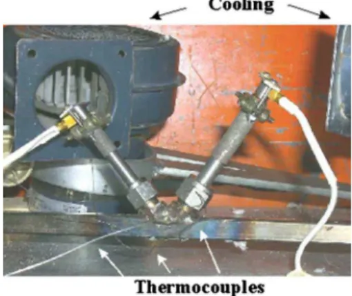
A Thermocast™ heater machine provides flow of Shell Ther-mia® oil Cat temperatures near 130° C. This machine is used to demonstrate the high temperature flow speed measurement by the flowmeter. Because of the different operating temperature and liq-uid media considered now, buffer rod angles and separation L between probes have to be re-evaluated. An incident angle of 40 deg is still an effective design value关27兴. Due to high impedance mismatch between steel and Thermia-C oil at 130° C, there is a decrease of the ultrasonic energy transmitted into the oil and de-tected by the flowmeter关27兴. The angle of refraction in hot oil is further reduced, yielding L = 4.99 mm. Thus, the cladding close to the probing end was partially removed, resulting in a minimum separation L = 8 mm. A flowmeter was then implemented. The CBRs were welded into the duct wall, flush with the duct inner surface. Figure 8 illustrates the CBRs installation, fans to cool down the CBR UT extremities, and three type-K thermocouples to sense the temperature of the flowmeter in the vicinities of the CBRs. The temperature data are sent over a GPIB interface to the Pentium® PC, and the LABVIEW® program acquires temperature and ultrasonic signals simultaneously.
Proper functionality of the flowmeter system at high tempera-ture, such as generation and detection of ultrasonic signals, proper cooling of the UTs, and absence of hot oil linkage, have been verified. Typical ultrasonic signals acquired for downstream and upstream operations are shown in Fig. 9. It was demonstrated earlier that the superior SNR of the CBRs over the nonclad rods leads to detection of two echoes, namely, S1− S1and S1− L
1− S1.
Figure 10, which is intended to illustrate the ultrasonic beam paths
Fig. 5 A contrapropagating ultrasonic flowmeter prototype for water flow measurements at room temperature. For down-stream transit time measurements, probe B is the receiver; for upstream transit time measurements, probe A is the receiver.
Fig. 6 Typical ultrasonic signals obtained with the flowmeter prototype in Fig. 5
Fig. 7 Experimental and theoretical results for the contra-propagating ultrasonic flowmeter shown in Fig. 5
Fig. 8 Implementation of the contrapropagating ultrasonic flowmeter designed for high temperature operation
in the designed flowmeter, explains the origin of such echoes. The
S1− S1echo is originated by shear waves propagating along paths 1,2,3 and 3,2,1 for downstream and upstream operations, respec-tively. Its transit time is tTdor tTu, shown in Fig. 9, where d and u subscripts stand for downstream and upstream, respectively. The
S1− L1− S1 echo propagates as shear waves in the transmitter
CBR and is converted into longitudinal waves in the solid/liquid interface. After sensing the liquid, longitudinal waves are con-verted back into shear waves in the liquid/solid interface and are finally detected by the receiving shear UT. For downstream and upstream measurements, S1− L1− S1 propagates along paths
1,4,5,3 and 3,5,4,1, respectively. Accordingly, the transit times associated with these paths are tdor tu. Thus, downstream signals are characterized by a pair of transit times共tTd, td兲, while upstream
signals are characterized by共tTu, tu兲.
It has been observed that downstream and upstream transit times tTdand tTuof the S1− S1echo are linearly related with the
average temperature measured by thermocouples simultaneously with the acquisition of the ultrasonic signals. For instance, at zero flow rate in the output of the Thermocast™ machine, this linear relationship is shown in Fig. 11. In this figure, the temperature is the average value of three thermocouples. Therefore, measure-ment of transit times tTd and tTu offers a means to calibrate the
flowmeter with respect to the temperature of the flow. In other words, tTdand tTumay be used as temperature reference to
ascer-tain that downstream tdand upstream tutransit times have been taken at the same temperature. This is the essence of the tempera-ture effect compensation here proposed in order to reduce mea-surement errors in the contrapropagating flowmeter. It is possible because the SNR of CBRs is high enough to reveal the existence of the S1− S1echo in contrast to the reported nonclad rods.
In order to demonstrate the technique of temperature effect compensation thus devised, downstream and upstream signals were acquired nonsimultaneously for three different scenarios:
maximum flow rate provided by the Thermocast™ machine, 60% of the maximum flow共intermediate flow兲 rate, and zero flow rate. In all cases, acquisitions started at temperatures around 134° C, prolonging until about 130° C. Signals were acquired at 50 MHz sampling rate and averaged 50 times. Acquisitions were estimated to take one averaged signal per second. For each flow rate, the downstream and upstream pairs共T , tT兲 共thermocouple temperature
and S1− S1 transit time, respectively兲 and 共t
T, t兲 共S1− S1 and S1
− L1− S1transit times, respectively兲 were stored in the PC. The
common temperature T for downstream and upstream operations was then found, resulting in the pairs共tTd, td兲 and 共tTu, tu兲. At this
point, Eq.共4兲 holds to determine flow speed from measurements of downstream and upstream times at the same temperature. Equivalent to the pairs 共tTd, td兲 and 共tTu, tu兲 are the new pairs
共tTd, td− tTd兲 and 共tTu, tu− tTu兲. The latter takes into account the
propagation of S1− L1− S1 in liquid paths 4,5 and 5,4,
respec-tively, rather than in solid paths 1,3 and 3,1, as seen in Fig. 10. However, it was noted that at zero flow rate upstream and down-stream curves do not match, as mentioned in Sec. 4 and illustrated in Fig. 11. This means that a calibration factor must be applied to the flowmeter system. The calibration factor used here is given by a straight line over the measurement range and results from sub-traction of the linear regressions of the experimental points for the case of zero flow. Flow measurements are then corrected by low-ering the upstream transit time curves with the calibration factor curve, and the S1− L1− S1transit times are now designated as tF
− tT. Finally, Figs. 12共a兲 and 12共b兲 show the relation between times tT and tF− tT for 60% and 100% of maximum flow speed,
respectively.
The difference between upstream and downstream transit times can be readily obtained from the latter plots. But in order to high-light the temperature variation during measurements, we trans-formed the transit time tTinto temperature through the linear
re-lation found between them using either downstream or upstream
tT curve. For this demonstration, we chose the downstream tT curve. In addition, the difference between upstream and down-stream transit time共tu− td兲 was defined by linear regression rather
than using the experimental points, allowing continuous subtrac-tion over the measurement interval. Results are shown in Fig. 13. As expected, the difference in transit time for the intermediate flow is about 60% of that for the maximum flow in the measure-ment range. Moreover, the linear curves of Fig. 13 have positive inclination since an increase in temperature results in reduction of the ultrasonic velocity c in liquids; accordingly, the difference between upstream and downstream transit times increases, as shown by Eq.共4兲. Based on the accuracy obtained by the appara-tus in the water flow experiment at constant temperature, an error of 1 ns for the difference in transit times was estimated. In future investigations, the flowmeter here designed is intended to be used in flow speed measurements of different industrial fluids and may also be modified into a Doppler-type flowmeter to measure
mul-Fig. 9 Typical ultrasonic signals obtained with the contra-propagating ultrasonic flowmeter shown in Fig. 8
Fig. 10 Ultrasonic beam paths in the contrapropagating ultra-sonic flowmeter
Fig. 11 Linear relation between the average temperature in the liquid flow and the ultrasonic transit times „upstream and downstream… of the S1− S1echo for the flowmeter shown in Fig.
tiphase flows, such as bubbles and cavitating structures. As a final remark, it is worth mentioning that although experiments have been carried out at temperatures near 130° C, the steel CBRs can properly operate at temperatures up to 960° C关26兴.
6 Conclusion
A contrapropagating ultrasonic flowmeter employing steel CBRs was designed for operation at temperatures higher than 100° C, being immune to temperature variation. This ultrasonic flowmeter is driven by shear wave UTs, which generate longitu-dinal waves to sense the flow speed through mode conversion at the chamfered probing end of the CBRs.
One pair of steel CBRs and another pair of nonclad steel buffer rods, having both the same lengths and diameters, were assembled in contrapropagating configuration in water, being the probing ends cut at 40 deg. It was demonstrated that the SNR of CBRs was superior to that of nonclad buffer rods even in the through-transmission mode, which is a standard way to operate contra-propagating flowmeters.
Thus, a contrapropagating flowmeter prototype made with steel CBRs was designed for operation with water flow at room tem-perature. Effects of water flow speeds on the difference between upstream and downstream ultrasonic transit times were measured and compared with theoretical expectations. Good repeatability of measurements and agreement with theory were achieved. An ac-curacy of 1 ns for the difference between upstream and down-stream ultrasonic transit times 共which is proportional to flow speed at constant temperature兲 was reached. Motivated by such
results, a contrapropagating flowmeter was then designed and in-stalled in a heater machine for flow speed measurements of hot oil 共Thermia-C兲 at temperatures near 130° C. It was shown that these CBRs could generate specific ultrasonic signals to be used in tem-perature calibration of flowmeters, allowing temtem-perature variation while still measuring accurately the flow speed. For a 3 ° C tem-perature range, the difference between upstream and downstream ultrasonic transit times was measured within 1 ns accuracy共this is the accuracy claimed in the water flow measurement at constant temperature兲.
Acknowledgment
The authors would like to thank J. Dufour共IMI-NRC兲 for valu-able technical assistance. D.R.F. acknowledges a fellowship from CNPq–Brazil.
References
关1兴 Brown, E. C., Dawson, A. J., and Coates, P. D., 2001, “Ultrasonic Measure-ments in the Nozzle and Cavity During Polymer Injection Molding,” Proceed-ings of the Polymer Processing Society Conference, Paper No. 320, pp. 1–11. 关2兴 Spitzer, D. W., 2001, Flow Measurement, Instrument Society of America,
Re-search Triangle Park, NC.
关3兴 Liu, Y., Lynnworth, L. C., and Zimmerman, M. A., 1998, “Buffer Waveguides for Flow Measurement in Hot Fluids,” Ultrasonics, 36, pp. 305–315. 关4兴 Jen, C.-K., Piché, L., and Bussiérre, J.-F., 1990, “Long Isotropic Buffer Rods,”
J. Acoust. Soc. Am., 88共1兲, pp. 23–25.
关5兴 Jen, C.-K., Cao, B., Nguyen, K. T., Loong, C. A., and Legoux, J.-G., 1997, “On-Line Ultrasonic Monitoring of a Die Casting Using Buffer Rods,” Ultra-sonics, 35共5兲, pp. 335–344.
关6兴 Jen, C.-K., Chen, J.-Y., Hoa, S. V., Nguyen, K. T., Legoux, J.-G., and Hébert, H., 1997, “Clad Buffer Rods for In-Situ Process Monitoring,” Proc.-IEEE Ultrason. Symp., 1, pp. 801–806.
关7兴 França, D. R., Jen, C.-K., Nguyen, K. T., and Gendron, R., 2000, “Ultrasonic In-Line Monitoring of Polymer Extrusion,” Polym. Eng. Sci., 40共1兲, pp. 82– 94.
关8兴 Ihara, I., Jen, C.-K., and França, D. R., 2000, “Ultrasonic Imaging, Particle Detection and V共z兲 Measurements in Molten Zinc Using Focused Clad Buffer Rods,” Rev. Sci. Instrum., 71, pp. 3579–3586.
关9兴 França, D. R., Wen, S.-S. L., Jen, C.-K., Nguyen, K. T., and Hébet, H., 1997, “Advances in On-Line Monitoring of Polymer Injection Molding Process,” Proc.-IEEE Ultrason. Symp., 1, pp. 807–810.
关10兴 Jen, C.-K., Nguyen, K. T., Legoux, J.-G., Ihara, I., Hebert, H., and França, D. R., 1998, “Novel Clad Ultrasonic Buffer Rods for the Monitoring of Industrial Materials Processing,” The First Pan-American Conference for NDT, pp. 99– 106.
关11兴 Ihara, I., Jen, C.-K., and França, D. R., 1998, “Materials Evaluation Using Long Clad Buffer Rods,” Proc.-IEEE Ultrason. Symp., 1, pp. 803–807. 关12兴 França, D. R., Jen, C.-K., and Ono, Y., 2001, “Ultrasonic Measurement of
Liquid Flow at Elevated Temperature,” The International Acoustic Imaging Symposium, Windsor, ON.
关13兴 Ono, Y., Moisan, J.-F., and Jen, C.-K., 2003, “Ultrasonic Techniques for Im-aging and Measurements in Molten Aluminum,” IEEE Trans. Ultrason. Ferro-electr. Freq. Control, 50共12兲, pp. 1711–1721.
关14兴 Rehman, A.-U., Jen, C.-K., and Ihara, I., 2001, “Ultrasonic Probes for High Temperature Immersion Measurements,” Meas. Sci. Technol., 12, pp. 306– 312.
关15兴 Sun, Z., and Jen, C.-K., 2001, “Ultrasonic Monitoring of Polymer Residence
Fig. 12 Downstream and upstream transit time measurements after applying the calibration factor for correcting differences of downstream and upstream transit times at zero flow speed. „a… 60% of maxi-mum flow speed. „b… 100% of maximaxi-mum flow speed.
Fig. 13 Experimental results demonstrating the temperature tracking capability of the S1− S1echo for two speeds of hot oil
flow. Upstream and downstream transit times can be measured at the same temperature by the apparatus, allowing precise flow speed measurements over the temperature range.
Time Distribution Inside Extruder Barrel,” Proceedings of the Polymer Pro-cessing Society Conference, Paper No. 248, pp. 1–5.
关16兴 Jen, C.-K., França, D. R., Sun, Z., and Ihara, I., 2001, “Clad Polymer Buffer Rods for Polymer Process Monitoring,” Ultrasonics, 39, pp. 81–89. 关17兴 Jen, C.-K., Legoux, J.-G., and Parent, L., 2000, “Experimental Evaluation of
Clad Metallic Buffer Rods for High Temperature Ultrasonic Measurements,” NDT & E Int., 33, pp. 145–153.
关18兴 Scelzo, M., and Jacobson, S., 1994, “Transit-Time Ultrasonic Flowmeter With Patented Signal-Coding,” Meas. Control, 164, pp. 84–87.
关19兴 Lynnworth, L. C., 1989, Ultrasonic Measurements for Process Control—
Theory, Techniques, Applications, Academic, New York, p. 414.
关20兴 Lynnworth, L. C., 1979, “Ultrasonic Flowmeters,” Physical Acoustics, Aca-demic, New York, Vol. 14, Chap. 5.
关21兴 Munk, W. D., 1982, “Ultrasonic Flowmeter Offers New Approach to Large-Volume Gas Measurement,” Oil Gas J., 80共36兲, pp. 111–117.
关22兴 Cook, F. B., and Moffatt, E. M., 1974, “Flowmeter for High Pressure Gas
Using Sonic Pulses,” Advances in Instrumentation, in press.
关23兴 Auld, B. A., 1990, Acoustic Fields and Waves in Solids, Robert E. Krieger, Malabar, FL, Vols. I and II.
关24兴 Rose, J. L., 1999, Ultrasonic Waves in Solid Media, Cambridge University Press, Cambridge, UK.
关25兴 Krautkrämer, J., and Krautkrämer, H., 1990, Ultrasonic Testing of Materials, 4th ed., Springer-Verlag, Berlin.
关26兴 França, D. R., 2001, “Ultrasonic Monitoring of Material Processing Using Clad Buffer Rod Sensors,” Ph.D. thesis, McGill University, Montréal, QC, Canada.
关27兴 Lynnworth, A. M., and Lynworth, L. C., 1985, “Calculated Turbulent-Flow Meter Factors for Nondiametral Paths Used in Ultrasonic Flowmeters,” J. Flu-ids Eng., 107, pp. 44–48.
关28兴 van Deventer, J., and Delsing, J., 2002, “Apparent Transducer Non-Reciprocity in an Ultrasonic Flowmeter,” Ultrasonics, 40, pp. 403–405.