Publisher’s version / Version de l'éditeur:
Vous avez des questions? Nous pouvons vous aider. Pour communiquer directement avec un auteur, consultez la première page de la revue dans laquelle son article a été publié afin de trouver ses coordonnées. Si vous n’arrivez pas à les repérer, communiquez avec nous à [email protected]. Questions? Contact the NRC Publications Archive team at
[email protected]. If you wish to email the authors directly, please see the first page of the publication for their contact information.
https://publications-cnrc.canada.ca/fra/droits
L’accès à ce site Web et l’utilisation de son contenu sont assujettis aux conditions présentées dans le site LISEZ CES CONDITIONS ATTENTIVEMENT AVANT D’UTILISER CE SITE WEB.
Third International Symposium on 3D Data Processing, Visualization and
Transmission (3DPVT 2006) [Proceedings], 2006
READ THESE TERMS AND CONDITIONS CAREFULLY BEFORE USING THIS WEBSITE. https://nrc-publications.canada.ca/eng/copyright
NRC Publications Archive Record / Notice des Archives des publications du CNRC :
https://nrc-publications.canada.ca/eng/view/object/?id=28d2b039-f9be-4a39-93a2-79d20fbd3db6
https://publications-cnrc.canada.ca/fra/voir/objet/?id=28d2b039-f9be-4a39-93a2-79d20fbd3db6
NRC Publications Archive
Archives des publications du CNRC
This publication could be one of several versions: author’s original, accepted manuscript or the publisher’s version. / La version de cette publication peut être l’une des suivantes : la version prépublication de l’auteur, la version acceptée du manuscrit ou la version de l’éditeur.
Access and use of this website and the material on it are subject to the Terms and Conditions set forth at
Automatic Locating of Anthropometric Landmarks on 3D Human
Models
National Research Council Canada Institute for Information Technology Conseil national de recherches Canada Institut de technologie de l'information
Automatic Locating of Anthropometric
Landmarks on 3D Human Models *
Ben Azouz, Z., Shu, C., and Mantel, A.
June 2006
* published at the Third International Symposium on 3D Data Processing, Visualization and Transmission (3DPVT 2006). Chapel Hill, North Carolina, USA. June 13-16, 2006. NRC 48723.
Copyright 2006 by
National Research Council of Canada
Permission is granted to quote short excerpts and to reproduce figures and tables from this report, provided that the source of such material is fully acknowledged.
Automatic Locating of Anthropometric Landmarks
on 3D Human Models
Zouhour Ben Azouz
Chang Shu
Visual Information Technology Group
Institute for Information Technology
National Research of Canada
Ottawa, K1A 0R6, Canada
{Zouhour.Benazouz, Chang.Shu}@nrc-cnrc.gc.ca
Anja Mantel
Stuttgart University of Applied Sciences
Schellingstr.24
Stuttgart, 70174, Germany
[email protected]
Abstract
We present an algorithm for automatic locating of an-thropometric landmarks on 3D human scans. Our method is based on learning landmark characteristics and the spa-tial relationships between them from a set of human scans where the landmarks are identified. The learned informa-tion is formulated by a pairwise Markov network. Each node of the network is a random variable corresponding to the position of a landmark. The edges of the network repre-sent correlations between the positions of landmark pairs. Probabilistic inference is then performed over the Markov network to locate the landmarks. We evaluated the algo-rithm on 30 human models with different shapes. The re-sults showed good accuracy for most of the landmarks.
1. Introduction
The remarkable progresses made in body scanning tech-niques during the last decade has led to increasing interests in 3D anthropometry. Currently, full-length human body can be digitized efficiently, providing tremendous amount of information about the shape of the human body. The 3D data can be used to measure, compare, and conduct statis-tics and has applications in, for example, ergonomic design of products such as automobiles, furniture, and clothes.
Processing the surface data collected by the sensors, however, proves to be a challenge. The main difficulty is that the digitized models have different number of points and there is no correspondence between different models. This correspondence information is essential to many appli-cations such as variability study and animation [4][1]. An-other difficulty is that the data is noisy and often incomplete. Allen et al. [1] solved the correspondence problem by deforming a template model to fit individual scans. The
re-sulting models all have the same number of triangles and point-to-point correspondences. The deformation relies on a set of anthropometric landmarks provided in the CAESAR (Civilian American and European Surface Anthropometry Resource) database [14]. These landmarks were marked on the measured subjects prior to scanning. They provide the seed correspondences that guide the deformation of the rest of the points. Unfortunately, the marking process consider-ably increases the time of measurement – from a few sec-onds to more than 30 minutes. Consequently, this step raises the cost of 3D anthropometric data collection and will most likely be avoided in the future projects.
Ben Azouz et al. [4] used a volumetric representation of the surface models to establish the correspondences be-tween the different models. This landmark-free approach allows the comparison and the extraction of certain modes of variation of the human body. However, it has the limita-tion that the volumetric representalimita-tion provides only an ap-proximation of the anthropometric correspondence between different human models.
In this paper we present a technique to locate landmarks without prior marking. Our method is based on statistical learning. We take advantage of the landmarks placed by ex-perts during recent 3D anthropometric surveys such as the CAESAR project. Most anthropometric landmarks repre-sent skeletal features and must be found by palpation. They correlate with surface geometric features in a subtle way. They correspond to a stable set of points on every human body. Through many years of study, anthropometrists have developed strict standards for the locations of these land-marks. With enough instances of these landmarks, we can learn their statistical characteristics and use them to guide our search for their locations on the 3D models.
We model the positions of the landmarks as random vari-ables. The probability of a surface point to be a particular landmark depends on the local surface properties as well
as its relationships with other landmarks. These constraints are naturally modeled by Markov Random Field (MRF) or Markov network. In the training stage, the distributions of surface geometric properties such as SPIN images [10], and the relative positions of landmark pairs are computed. In the subsequent matching stage, landmarks are located on an in-stance of 3D human model by identifying the surface points that maximizes the joint probability defined by the Markov network. This probability optimization problem is solved efficiently by the belief propagation technique developed in statistical learning [18].
The rest of the paper is organized as follows. In Section 2 we review previous work. We describe our algorithm in Section 3. The results of locating landmarks in 3D human scans are presented in Section 4. Finally, we present our conclusions and future work in Section 5.
2. Previous Work
Currently, the dominant way to locate anthropometric landmarks relies on placing markers on the human body prior to scanning [8] [11] [5] [15]. These methods are te-dious and time-consuming. Therefore the cost of future projects of 3D anthropometric data collection can be re-duced if pre-marking is eliminated or just applied to a few subjects. In the literature there are some attempts to lo-cate anthropometric landmarks automatically without prior marking. Most of this work are limited to locating branch-ing points such as the armpits and the crotch [13] [12] [16] [17]. Dekker [6] extends the identification to a larger subset of landmarks. The approach is based on defining for each landmark a function that combines different attributes. For instance, the acromion (shoulder point) is located as “the first point on the torso, traversing down from the nape on the ridge line of maximum z where the gradient is less than g and then a gradient greater than h” [6]. The limitation of the existing automatic methods is that they can not be extended to all the anthropometric landmarks. Also, the published results concern the accuracy of traditional mea-surement that are extracted from the located landmarks but not the accuracy of the landmark positions.
Recently, Anguelov et al. [2] proposed an unsupervised method to register non-rigid surfaces. This method estab-lishes an embedding of an instance mesh into a template mesh using a Markov network. The algorithm assigns for each vertex of the instance mesh a corresponding vertex on the template mesh. Anguelov et al. [3] applied this al-gorithm to 3D human scans in order to select around 200 corresponding points between the template model and the instance models. These points are then used as landmarks to guide the deformation of the template model to fit their corresponding instance models. The approach can poten-tially be used to identify anthropometric landmarks of the
instance models, provided that the landmarks on the tem-plate model are identified. However, the algorithm requires an initialization by placing 4 to 10 markers manually on each pair of scans. Moreover, the published results did not quantify the accuracy of the correspondences.
The approach we propose in this paper differs from the previous work in two aspects. First, our algorithm is super-vised. It is based on a training set of 3D human scans where the position of standard anthropometric landmarks (Fig-ure 1) are identified. Second, our algorithm uses Markov network to represent the landmarks and the relationship be-tween them. In comparison, the Markov network used by Anguelov et al. [2] represents the whole mesh of the model, a much larger graph, and is thus harder to solve. Our work can be seen as the extension of the method that uses prob-abilistic graphical models for object recognition in 2D im-ages [7].
3. Algorithm
We formulate the landmark locating problem as a prob-abilistic inference problem, where the inference is over a pairwise Markov random field. Here, our goal is to find the most likely assignment to the entire set of the landmarks. Markov random field is an instance of probabilistic graph-ical model. The central element of this model is a graph in which the nodes correspond to random variables. These models have been used in computer vision for object match-ing and recognition. For example, Felzenszwalb [7] used undirected graph models to find instances of an object in an image. The object is represented by a pictorial structure model that is a collection of parts with connections between certain pairs of parts.
The landmark locating process consists of two main steps. In the first step, we define and learn the parameters of a pairwise Markov random field. In the second step, we perform probabilistic inference to find the optimal labeling of the landmarks.
3.1
Pairwise Markov Random Field
A Markov random field, or Markov network, is a model of the joint probability distribution of a set of random vari-ables. For our application these random variables are L = {l1, l2, ...ln} the positions of the n landmarks. A Markov
network consists of an undirected graph G= (V, E), where each node v from V represents a random variable in L and each edge{li, lj} from E represents a dependency between
the random variables li and lj. In a pairwise Markov
net-work a potentials φi(li) is associated to each node i. This
potential represents the likelihood that a landmark li
cor-responds to a given vertex on the surface. For each edge {li, lj} we associate a compatibility potential ψij(li, lj) to
Figure 1. Anthropometric landmarks used in the CAESAR project: the anthropometric nomenclature of these landmarks is given in Table 1.
constrain the positions of these landmarks to be consistent with their spatial relationship. The joint probability associ-ated with this landmark is given by:
p(L) = 1 Z Y i φi(li) Y i,j ψij(li, lj) (1)
where Z is a normalizing factor. In order to locate the landmarks, the potentials φi(li) and ψij(li, lj) of the MRF
should encode a preference of the local surface properties around the landmarks and maintain the spatial relationship between landmark pairs. In the following two sub-sections we define the surface attributes used to describe the land-marks. We also characterize the spatial relationship be-tween landmark pairs.
3.1.1 Surface Attributes
To characterize the local surface features, we use SPIN Im-ages [10]. A SPIN image is a two-dimensional histogram computed at an oriented point of a surface mesh. An ori-ented point at a vertex is defined by the 3D position and the surface normal at the vertex. Two cylindrical coordinates (α, β) can be defined with respect to an oriented point as shown in Figure 2.
To compute the SPIN image, a 2D accumulator indexed by α and β is created. The coordinates (α, β) are com-puted for each vertex of the surface that is within a defined distance of support. The bin indexed by(α, β) in the accu-mulator is then incremented. The resulting accuaccu-mulator is
Figure 2. Coordinate system used to compute the spin image on a point surface.
then represented as an image where dark areas correspond to bins that contain many projected points.
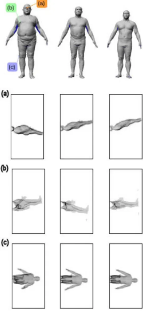
Examples of SPIN images computed on 3 different hu-man models for 3 landmarks are shown in Figure 3. We notice the similarity between the SPIN images correspond-ing to the same landmarks for different models.
SPIN image is a high dimensional descriptor that char-acterizes the local surface geometry around a vertex. How-ever, it is not directly useful because its dimension is too high. To reduce the dimension to a managable size, we use the standard Principal Component Analysis (PCA). We first compute an eigenspace from SPIN image of several mod-els. The SPIN image of each model is then characterized by its projection on the most significant eigenvectors.
Figure 3. Spin Images computes for three landmarks on three different human models. (a) Sellion.(b) Rt. Thelion. (c) Rt. Femoral Lateral epicn.
3.1.2 Spatial relationship between landmark pairs The anthropometric landmarks are constrained to a spatial relationship that is the same for all the human models. For instance the positions of the right acromion and the left acromion are approximately symmetric. The right and left ifrorbitale are below the sellion. In order to encode these constraints in the Markov network, we propose to charac-terize the edges pairs by the position of a landmark relative to its neighboring landmarks.
3.1.3 Learning
The advantage of representing landmarks by a graph is to model the correlation between the positions of landmarks. In our current implementation, we manually construct a graph to link pairs of landmarks (Figure 4). This graph does not necessarily express optimal correlations between
land-Figure 4. Structure of the landmark graph.
marks. This aspect will be addressed in our future work. In the learning step we identify the parameters of the po-tentials attributed to the nodes and the edges of the Markov network. We model the potential associated to each node φi(li) by a Gaussian distribution of the SPIN image
com-puted on the corresponding landmark. The parameters of the potential,(µi,Σi), are the mean vector and the
covari-ance matrix. The potential that a landmark i is located on the vertex vkis:
φi(li= vk) = N (S(vk), µi,Σi) (2)
whereN is a multivariate Gaussian with mean vector µiand
covariance matrix Σi, and S(vk) is the SPIN image
com-puted on vertex vk.
The potential ψij(li, lj) is the Gaussian distribution of
the relative position of landmark ljwith respect to landmark
li.
We normalize the height of 3D human scans. This nor-malization has two main advantages. First, it eliminates the variability in the landmark positions that is due to a scale variation and not to the body shape variation. Second, after normalization we can learn a distribution for the position of each landmark. This distribution can be used to limit the search space in the landmark locating stage.
3.2
Probabilistic Inference
The goal of probabilistic inference over a Markov net-work is to find assignments for the random variables that maximize the joint probability defined in equation 1.
When the number of nodes is large, exact inference is computationally infeasible. Instead, we apply the approx-imate inference method known as loopy belief propaga-tion[18]. This method is based on iteratively propagating messages between adjacent nodes.
In each iteration, a node i updates the messages sending to each of its neighbors j about what position they should be in: mij(lj) = X li φi(li)ψij(li, lj) Y k∈N (i)\{j} mki(li) (3)
After convergence, for each node we compute the belief that it be at a given position as follows:
bi(li) = Kφi(li)
Y
j∈N (i)
mji(li) (4)
where K is a normalization constant.
We approximately obtain the most likely configuration of the nodes by assigning for each node the position corre-sponding to the highest belief.
4. Experimental Results
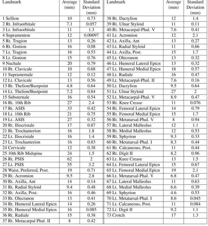
We applied our algorithm to 230 human scans from the CAESAR database, in which the positions of 73 anthropo-metric landmarks, as shown in Figure 1, are available for all the models. We used 200 scans for learning and the rest 30 scans for validation. The Euclidean distances between the predicted landmark positions and their corresponding po-sitions placed by the anthropometry experts are calculated. When computing the locations of the landmarks, the heights of all the models are normalized to 1 metre, but the errors are calculated using the models in their original scale. Fig-ure 5 illustrates the results of the landmark locating for a wide variety of human body shapes. Table 1 shows the av-erage and standard deviation of the location errors for each landmark.
We notice that for most of the landmarks the error is less than 2cm. It is important to mention that the landmarks we use as reference are subject to uncertainties, since dif-ferent measurer place the same landmark at slightly differ-ent positions. Gordon et al. [9] reported the accuracy of the traditional 1D measurements. This study used the mean absolute differences to indicate the variances between re-peated measurements of the same subjects. A maximum allowable error is derived from these values. The variation of results produced by different measurer is due in part to the difference in interpreting the anthropometric landmarks when they palpate the body to take the measurements. For most of the traditional measurements the accepted error is around1cm.
5. Conclusions
We have presented an algorithm for automatically locat-ing anthropometric landmarks in human body scans. Our
method makes use of the landmark data placed by an-thropometric experts in the recent anan-thropometric surveys. Through the use of these data, we train a set of parameters that relates the landmark location with local surface prop-erties. The assigning of landmark labels to the vertices of each instance model is achived by solving a graphical prob-abilistic optimization problem. Our experiments show that accurate landmarks can be found by using this method.
The use of anthropometric landmark data for training is the key to our success. Since anthropometric landmarks cor-respond to skeletal positions, they are a set of stable posi-tions on the human body. Exploiting the knowledge em-bedded in these data allows us to locate the landmarks ac-curately.
The landmarks found in the human body scans are es-sential to subsequent processing of the 3D human models. They can be used for deforming a template model to each instance scan so that all models are in correspondence. They can also be used to make traditional anthropometric mea-surements.
The current results of our algorithm can be improved in several ways. There are different parameters that influence the results. One of these parameters is the support distance for computing the SPIN images. In our current experiments we choose a small support distance. This means that few vertices around an oriented point participate in the compu-tation of the SPIN image. The accuracy of landmarks can also be improved by integrating other surface descriptors.
Currently we characterize the relationship between land-marks uniquely by the relative position of a given landmark with respect to its neighbor. Landmark locating may be im-proved by encoding other constraints such as the relative orientation of surface normals and principal curvature di-rections between the landmarks.
The use of Gaussian distribution to define the potentials attributed to the nodes and edges of the Markov network is only suggestive. Other distributions such as a mixture of Gaussians can improve the accuracy of landmark location.
For the current experiment we manually construct a graph to link pairs of landmarks. Identifying automatically the most correlated landmarks will potentially enhance the algorithm.
References
[1] B. Allen, B. Curless, and Z. Popovic;. The Space of Hu-man Body Shapes: Reconstruction and Parametrisation from Range Scans. ACM Transactions on Graphics (ACM
SIG-GRAPH’2003), 22(3):587–594, 2003.
[2] D. Anguelov, P. Srinivasan, D. Koller, S. Thrun, H. Pang, and J. Davis. The correlated correspondence algorithm for unsupervised registration of nonrigid surfaces. In Advances
[3] D. Anguelov, P. Srinivasan, D. Koller, S. Thrun, J. Rodgers, and J. Davis. Scape: shape completion and animation of people. ACM Trans. Graph., 24(3):408–416, 2005. [4] Z. B. Azouz, C. Shu, R. Lepage, and M. Rioux. Extracting
Main Modes of Human Shape Variation from 3-D Anthropo-metric Data. In Proceedings of the Fifth International
Con-ference on 3-D Digital Imaging and Modeling (3DIM’05), Ottawa, Canada, June 2005.
[5] D. Burnsides, M. Boehmer, and K. Robinette. 3-D Land-mark Detection and Identification in the Caesar Project. In
Proceedings of the Third International Conference on 3-D Digital Imaging and Modeling (3DIM’2001), pages 393– 398, Quebec City, Canada, May 2001.
[6] L. Dekker, I. Douros, B. Buxton, and P. Treleaven. Build-ing Symbolic Information for 3D Human Body ModelBuild-ing from Range Data. In Proceedings of the Second
Interna-tional Conference on 3-D Digital Imaging and Modeling (3DIM’99), pages 388–397, Ottawa, Canada, October 1999. [7] P. Felzenszwalb and D. Huttenlocher. Pictorial structures for object recognition. International Journal of Computer
Vision, 61(1), 2005.
[8] G. Geisen, C. Mason, V. Houston, J. Whitestone, B. Mc-Quiston, and A. Beattie. Automatic Detection, Identification and Registration of Anatomical Landmarks. In
Proceed-ings of the 39th Annual Meeting of the Human Factors and Ergonomics Society, volume 2, pages 750–753, San Diego, 1995.
[9] C. Gordon, B. Bradtmiller, C. Clausen, T. Churchill, J. Mc-Conville, I. Tebbets, and R. Walker. Anthropmetric survey of US Army personnel. Method & summary statistics. Tech-nical Report TR-89-044, US Army Natick Research Devel-opment and Engineering Center, Natick, MA, 1989. [10] A. Johnson. Spin-Images: A Representation for 3-D Surface
Matching. PhD thesis, Robotics Institute, Carnegie Mellon University, Pittsburgh, PA, August 1997.
[11] F. Lewark and J. Nurre. Automated Fudicial Labeling on Human Body Data. In Proceedings of the
Three-Dimensional Image Capture and Applications, SPIE, vol-ume 3313, pages 82–89, San Jose, CA, January 1998. [12] J. Nurre. Locating Landmarks on Human Body Scan Data.
In Proceedings of the International Conference on Recent
Advances in 3-D Digital Imaging and Modeling (3DIM’97), pages 289–295, Ottawa, Canada, May 1997.
[13] R. Pargas, N.J.Staples, and J.S.Davis. Automatic Mea-surement Extraction for Apparel from a Three-Dimensional Body Scan. Optics and Lasers in Engineering, 28(2):157– 172, 1997.
[14] K. Robinette, H. Daanen, and E. Paquet. The Caesar Project: A 3-D Surface Anthropometry Survey. In Second
Inter-national Conference on 3-D Digital Imaging and Modeling (3DIM’99), pages 380–386, Ottawa, Canada, October 1999. [15] Y. Tai, S. Chao, and S. Yang. Automatic Detection and La-beling of Anatomical Landmarks on Virtual Human Model from 3D Laser Digitizer. In Proceedings of the International
Workshop on Advanced Image Technology (IWAIT), 2002. [16] C. Wang, T. Chang, and M. Yuen. From Laser-Scanned Data
to Feature Human Model: A System Based on Fuzzy Logic Concept. Computer Aided Design, 35:241–253, 2003.
[17] Y. Xiao, J. Siebert, and N.Werghi. Topological Segmenta-tion of Discrete Human Body Shapes in Various Postures Based on Geodesic Distance. The 17th International
Con-ference on Pattern Recognition (ICPR’04), IEEE Computer Society Press, pages 131–135, 2004.
[18] J. Yedidia, W. Freeman, and Y. Weiss. Understanding Belief
Propagation and Its Generalizations. Science & Technology Books, 2003.
Figure 5. Results of landmark locating on 4 human models. The red spots correspond to landmarks located in the CAESAR survey by prior marking and the green ones correspond to the landmarks located using our approach. Each row corresponds to a different view of the 4 human models.
Landmark Average Standard Landmark Average Standard (mm) Deviation (mm) Deviation
(mm) (mm)
1 Sellion 10 0.73 38 Rt. Dactylion 12 1.4 2 Rt. Infraorbitale 7.1 0.057 39 Rt. Ulnar Styloid 11 0.11 3 Lt. Infraorbitale 11 1.3 40 Rt. Metacarpal-Phal. V 7.6 0.41 4 Supramenton 12 0.00097 41 Lt. Acromion 12 2.1 5 Rt. Tragion 13 0.26 42 Lt. Axilla, Ant 13 0.27 6 Rt. Gonion 16 0.08 43 Lt. Radial Styloid 11 0.66 7 Lt. Tragion 16 0.53 44 Lt. Axilla, Post. 15 1.7 8 Lt. Gonion 15 0.76 45 Lt. Olecranon 13 0.32 9 Nuchale 20 0.79 46 Lt. Humeral Lateral Epicn 13 0.32 10 Rt. Clavicale 10 0.68 47 Lt. Humeral Medial Epicn 18 0.57 11 Suprasternale 12 0.12 48 Lt. Radiale 16 0.47 12 Lt. Clavicale 13 0.56 49 Lt. Metacarpal-Phal. II 7.6 0.16 13 Rt. Thelion/Bustpoint 4.8 0.64 50 Lt. Dactylion 9.5 0.64 14 Lt. Thelion/Bustpoint 7.2 0.84 51 Lt. Ulnar Styloid 27 2 15 Substernale 16 0.54 52 Lt. Metacarpal-Phal. V 8.9 0.47 16 Rt. 10th Rib 27 2.4 53 Rt. Knee Crease 11 0.076 17 Rt. ASIS 33 0.42 54 Rt. Femoral Lateral Epicn 14 0.79 18 Lt. 10th Rib 21 0.75 55 Rt. Femoral Medial Epicn 15 1.7 19 Lt. ASIS 27 0.32 56 Rt. Metatarsal-Phal. V 8 0.94 20 Rt. Iliocristale 17 0.87 57 Rt. Lateral Malleolus 12 1.1 21 Rt. Trochanterion 16 1.8 58 Rt. Medial Malleolus 12 0.53 22 Lt. Iliocristale 16 1.4 59 Rt. Sphyrion 9.3 0.33 23 Lt. Trochanterion 16 0.83 60 Rt. Metatarsal-Phal. I 8.3 0.44 24 Cervicale 12 0.38 61 Rt. Calcaneous, Post. 11 0.44 25 10th Rib Midspine 24 1.5 62 Rt. Digit II 8.2 0.96 26 Rt. PSIS 62 2 63 Lt. Knee Crease 13 1.5 27 Lt. PSIS 55 3.2 64 Lt. Femoral Lateral Epicn 15 0.67 28 Waist, Preferred, Post. 19 0.71 65 Lt. Femoral Medial Epicn 19 2.1 29 Rt. Acromion 9.5 2.8 66 Lt. Metatarsal-Phal. V 6.8 0.47 30 Rt. Axilla, Ant 14 0.14 67 Lt. Lateral Malleolus 11 0.63 31 Rt. Radial Styloid 9.4 0.48 68 Lt. Medial Malleolus 6.6 0.39 32 Rt. Axilla, Post. 16 0.46 69 Lt. Sphyrion 4.6 0.53 33 Rt. Olecranon 13 0.41 70 Lt. Metatarsal-Phal. I 8.6 0.045 34 Rt. Humeral Lateral Epicn 14 0.26 71 Lt. Calcaneous, Post. 11 0.084 35 Rt. Humeral Medial Epicn 16 0.085 72 Lt. Digit II 9.2 1.1
36 Rt. Radiale 15 0.38 73 Crotch 17 1.3
37 Rt. Metacarpal Phal. II 8 0.42