BiDi Screen: Depth and Lighting Aware Interaction and
Display
by
Matthew W. Hirsch
Submitted to the Program in Media Arts and Sciences,
School of Architecture and Planning,
in partial fulfillment of the requirements for the degree of
Master of Science in Media Arts and Sciences
at the
MASSACHUSETTS INSTITUTE OF TECHNOLOGY
August 2009
ARCHIVEb
'ASSACHUSETT8 INS EE OF TECHNOLOGYOCT 2 6 2009
LIBRARIES
@
Massachusetts Institute of Technology 2009. All rights reserved.
J.
Author
Program in Media Arts and Sciences
August 13, 2009
Certified by
Henry Holtzman Research Scientist Media Laboratory Thesis SupervisorAccepted by
Chair, Departmental Committee on
eb Roy
Graduo e Students
Program in Media Arts and Sciences
BiDi Screen: Depth and Lighting Aware Interaction and Display
by
Matthew W. Hirsch
Submitted to the Program in Media Arts and Sciences, School of Architecture and Planning,
on August 13, 2009, in partial fulfillment of the requirements for the degree of
Master of Science in Media Arts and Sciences
Abstract
In this thesis, I describe a new type of interactive display that supports both on-screen multi-touch interactions and off-screen hover-based gestures. This BiDirectional (BiDi) screen, capable of both image capture and display, is inspired by emerging LCDs that use embedded optical sensors to detect multiple points of direct contact. The key contribution of this thesis is to exploit the spatial light modulation capability of LCDs to allow dynamic mask-based scene capture without interfering with display functionality. A large-format image sensor is placed slightly behind the liquid crystal layer. By alternatly switching the liquid crystal between a display mode showing traditional graphics and a capture mode in which the backlight is disabled and a pinhole array or an equivalent tiled-broadband code is displayed, the BiDi Screen can recover multi-view orthographic imagery while functioning as a 2D display. The recovered imagery is used to passively estimate the depth of scene points from focus. I discuss the design and construction of a prototype to demonstrate these capabilities in two motivating applications: a hybrid touch plus gesture interaction and a light-gun mode for interacting with external light-emitting widgets. The working prototype simulates the large format light sensor with a camera and diffuser, supporting interaction up to 50 cm in front of a modified 20.1 inch LCD.
Thesis Supervisor: Henry Holtzman
BiDi Screen: Depth and Lighting Aware Interaction and Display
by
Matthew W. Hirsch
The following people served as readers for this thesis:
Thesis Reader
,
-Ramesh Raskar
Associate Professor of Media Arts and Sciences
Program in Media Arts and Sciences
Thesis
Reader-Joeseph Paradiso
Professor of Media Arts and Sciences
Program in Media Arts and Sciences
Acknowledgments
This work was conceived and developed in close collaboration with Prof. Ramesh Raskar, MIT Media Lab, and Douglas Lanman, a Ph.D. candidate at Brown University. Much of the theoretical analysis presented herein is reproduced from our SIGGRAPH Asia 2009 paper titled BiDi Screen: Depth and Lighting Aware Interaction and Display for which Douglas Lanman contributed the analysis. I sincerely thank Henry Holtzman, Prof. Ramesh Raskar and Douglas Lanman for their support and advice on completing this thesis. I also thank my friends and colleagues in the Information Ecology and Design Ecology groups, who have helped me keep my head in the clouds. Finally many thanks to Louise, who resents me only a little for all the late nights at the lab.
Contents
1 Introduction
1.1 A BiDirectional Display . ... 1.1.1 New Interaction Modes ... 1.1.2 Video Chat and Appearance Capture 1.2 Problem and Approach . ...
1.3 Contributions . ...
2 Background
2.1 Multi-touch and Gesture . ... 2.1.1 Light Sensitive Displays ...
2.1.2 Depth Sensitive and Light-field Cameras . 2.2 Bi-directional Displays . ...
2.3 Light-fields ...
2.3.1 Mask-Based Light-field Photography .
3 Bidirectional Display Design
3.1 Design Parameters . ... 3.2 LCD Overview ... 3.3 Hardware Design . ... 3.4 Optical Design . ... 3.4.1 Pinhole Arrays . ... 3.4.2 Broadband Masks ... 3.5 Gesture Detection ... 3.5.1 Depth Extraction . ... 3.5.2 Hand Tracking . ... 3.5.3 Touch Estimation ...
4 Prototype: Construction and
4.1 Implementation . . . . 4.1.1 Hardware . . . . 4.1.2 Software . . . . 4.2 Limitations . . . ... 4.3 Validation . . . ... 4.3.1 Resolution ... 4.3.2 Depth Resolution . Performance 45 45 45 47 53 54 54 55
4.3.3 Touch and Hover Discrimination . ... ... . . 55
4.4 User Experience ... ... .. 57
5 Interaction Modes 59 5.1 Multi-Touch and Hover ... ... . 59
5.1.1 Demonstrated. ... ... 59
5.1.2 Future Work ... ... ... 60
5.2 Lighting Sensitive Interaction ... ... 62
5.2.1 Demonstrated. ... ... 63
5.2.2 Future Work ... ... ... 63
5.3 Video and Appearance Capture ... ... 64
5.3.1 Demonstrated. ... ... 65 5.3.2 Future Work ... . .... ... 65 6 Conclusions 67 6.1 Future Work ... ... 67 6.1.1 Hardware ... .. ... 67 6.1.2 Variable Masks ... . . ... . 68 6.1.3 Video ... ... ... 68 6.1.4 Scanning ... ... 69 6.1.5 Handheld ... . ... . . 69 6.2 Synopsis ... ... ... .. 69
A Optimizing Heterodyne Mask Properties 71 A.1 Forward ... ... ... 71
A.2 Pinhole Array Mask Configuration ... .... 72
List of Figures
2-1 BiDirectional Screen Concept ... ... 21
2-2 Light-field: Single Plane Parametrization . ... 25
2-3 Light-field: Two Plane Parametrization ... . 26
3-1 Liquid Crystal Display Components ... ... 33
3-2 BiDi Screen Layout ... ... ... 34
3-3 Pinhole Camera Design ... ... 35
3-4 Multi-view Orthographic Imagery ... ... 37
3-5 Effective Spatial Resolution ... ... . . 38
3-6 Spatial and Angular Resolution Tradeoffs . ... 39
3-7 Synthetic Aperture Refocusing ... ... 42
4-1 Prototype Output ... . 48
4-2 Software Flow Control Diagram ... ... 49
4-3 Pinhole Calibration ... .... ... .... . 50
4-4 Thread Queue Job Ordering ... ... . 52
4-5 Performance Validation Results ... ... 54
4-6 Performance Validation Tests ... ... 56
5-1 Multi-touch Demonstration ... ... . 60
5-2 World Navigator Demonstration ... ... 61
5-3 Model Viewer Demonstration ... ... . . . 62
5-4 Lighting Demonstration ... . 63
5-5 Image Capture Result . ... . . . . . 64
A-1 Effective Spatial Resolution ... . . . . . 73
Chapter 1
Introduction
A novel method for using light sensors to detect multiple points of contact with the surface of liquid crystal displays (LCDs) is emerging. Sharp Corporation [7] and Planar Systems, Inc. [1] have demonstrated LCDs with arrays of optical sensors interlaced within the pixel grid. The location of a finger or stylus can be determined from the spatial position of occluded sensors that receive less light. For objects pressed directly against such screens, photographic imaging should be possible, but objects moved further away quickly become blurred as the light reflecting off any portion of the object is spread across many pixels.
In this thesis I describe how to modify traditional LCDs to allow both image capture and display. By using the LCD to display a pinhole array, or an equivalent tiled-broadband code [29], the angle and intensity of light entering a co-located sensor array may be captured. By correlating data from multiple views, it is possible to image objects, such as fingers, that are located beyond the display's surface and measure their distance from the display. This thesis describes the construction of a prototype device, in which imaging is performed in real-time, enabling the detection of off-screen gestures. When used with a light-emitting wand, the prototype can determine not only where the wand is aimed, but also the incidence angle of light cast on the display surface.
1.1
A BiDirectional Display
In this thesis I propose a BiDirectional (BiDi) screen, such that the entire surface of a thin, LCD-like device functions both as a display and a image capture device. The key component of a BiDi screen is a sensor array located slightly behind the spatial light modulating layer of a conventional LCD. The BiDi screen alternately switches between two modes: a display mode, where the backlight and liquid crystal spatial light modulator function as normal to display the desired output on the screen, and a capture mode where the backlight is disabled and the light modulator displays an array of pinholes or a tiled-broadband code. I demonstrate a working prototype of a BiDi screen, substituting a diffuser and conventional cameras for the sensor array. This prototype shows the BiDi screen in two motivating applications to demonstrate its depth and lighting-aware abilities: a hybrid touch plus gesture interaction, and a light-gun mode for interaction using a light-emitting widget.
1.1.1 New Interaction Modes
While earlier light-sensing display designs have focused on enabling touch interfaces, the BiDi screen enhances the field by seamlessly transitioning from on-screen multi-touch to off-screen hover and gesture-based interaction. Thus, the proposed device alternates between forming the displayed image and capturing a modulated light field through a liquid crystal spatial light modulator.
The interaction capabilities of the prototype BiDi Screen are presented in four demonstra-tions. A model viewer application (Figure 5.1), a world viewer (Figure 5.1), light-emitting widget interaction (Figure 5.2), and multi-touch demonstration (see Figure 5.1)
1.1.2 Video Chat and Appearance Capture
In this thesis I primarily explore the BiDi screen as an interaction device. However, the ability of this device to produce video data from a source coincident with a display creates
the opportunity for new applications in video chat. Current state-of-the-art systems for video chat employ a camera that is necessarily offset from a display screen. This creates an eye-gaze problem, whereby a user looking at the display screen (and not at the camera) appears not to make eye contact with the other party in the conversation. At a basic level, the collocated camera of the BiDi screen can be used to provide a realistic remote interaction between two people, free from the eye-gaze problem previously described. The BiDi screen is situated among other methods for addressing this problem in Chapter 2. Further applications for a coincident camera and display include interactive virtual mirrors and augmented reality displays.
Capturing a light-field in a wide-baseline sensor means that the BiDi screen could function as a 3D appearance capture device. An object could be held up to the screen and rotated in order to record a light-field map of its appearance.
1.2
Problem and Approach
The BiDi screen will enable a new dimension in interaction, allowing a seamless transition from a traditional multi-touch display to a new hover-based interactive device (Section 5.1). The BiDi screen is further capable of dynamically relighting virtual scenes with real-world light sources (Section 5.2). This technique clears the way for novel mixed-reality rendering applications. By collocating an image capture device with a display device, the BiDi screen potentially solves the problem of establishing eye-contact during a video chat (Section 5.3). This ability will also allow for novel dynamic mirror-world renderings, in which the BiDi screen functions as a mirror, optionally altering the world before displaying it on the screen. Mirror-world rendering will enable interesting games and information displays that use the player's own body as a canvas. The BiDi screen further functions as a wide-baseline light-field sensor. This means that the screen can function in an appearance-capture mode, in which the 3D physical appearance of an object can be captured in a single shot (also Section 5.3).
Some manufacturers [1] [7] are creating optical multi-touch displays, which place an optical sensor in each pixel of an LCD device. Such displays can produce an image of objects in contact with the surface of the screen, enabling a multi-touch interface. These devices contain no optics or equivalent so they cannot bring objects at any distance from the screen into sharp focus.
The BiDi screen modifies an optical multi-touch screen by translating the transparent sensor plane a short distance behind the LCD display (Figure 3-2). If a tiled broadband mask is displayed on the LCD, the sensor layer will record a modulated light-field, as described by the spatial heterodyning technique [51]. In the BiDi screen the LCD is then put to double duty, in that the display and modulation functions are time multiplexed. The LCD alternately displays an image for the viewer while enabling the backlight, and displays a tiled broadband mask for light-field modulation while disabling the backlight, and recording from the sensor. When the display mode of the LCD is time multiplexed above the flicker fusion frequency of the human visual system [56], users will perceive a steady image on the
screen.
In the prototype BiDi screen constructed for this thesis, a diffuser and camera system was used in place of a transparent sparse photosensor array. While the array would be preferable, practical constraints on time and budget required that the prototype be build from commodity hardware.
1.3
Contributions
The emphasis of this work is on demonstrating novel techniques for optical sensing enabled when an LCD and diffuse light-sensing grid are placed proximate to each other. As devices combining display and capture elements in close proximity are currently being developed commercially for multi-touch interaction, one goal is to influence the design of these displays by exploring design choices and illustrating additional benefits and applications that can be derived. This thesis only touches upon the interaction techniques enabled, leaving additional assessment to future work.
i:i~;;ii:i---;ii-~::~l~il_^~-i-~~l-~-_:-Earlier light sensing display designs have focused on promoting touch interfaces. The BiDi screen design enhances the field by supporting both on-screen multi-touch interactions and off-screen hover and gesture-based interfaces. A base contribution is that the LCD can be put to double duty; it can alternate between its traditional role in forming the displayed image and a new role in acting as an optical mask. It is shown that achieving per-pixel, depth and light aware interactions requires a small displacement between the sensing plane and the display plane. Furthermore, this work demonstrates a method that can maximize the display and capture frame rates using optimally light-efficient mask patterns.
In this thesis I describe a thin, lensless light field camera composed of an optical sensor array and a spatial light modulator. The performance of pinhole arrays and tiled-broadband masks for light field capture from primarily reflective, rather than transmissive, scenes is evaluated. I describe key design issues, including mask selection and the critical importance of angle-limiting materials.
I demonstrate that a BiDi screen can recognize on-screen as well as off-screen gestures, and its ability to detect light-emitting widgets, showing novel interactions between displayed images and external lighting.
I describe how the system can be expanded to support object appearance capture and novel video interactions with depth keying and eye contact between video chat participants.
Chapter 2
Background
The BiDi screen makes contributions in a diverse set of domains. In this chapter, I will situate the contributions of this thesis in the fields of touch and gesture interaction, specif-ically with respect to light sensing displays, depth sensing technology, collocated camera and display, and mask-based light-field photography.
2.1
Multi-touch and Gesture
Touch screens capable of detecting a single point of touch first appeared in a product in 1983 with Hewlett Packard's introduction of the HP-150 computer, although touch and pen systems existed earlier than this. Single-touch systems typically used transparent resistive or capacitive grids overlaid on a screen to sense touch. The pressure of a finger on the screen would induce a change in the resistance or capacitance of a few wires in the grid, allowing accompanying electronics to determine the position, and possibly pressure, of the touch.
Recently, much emphasis has been placed on enabling the detection of multiple simultane-ous touches on a screen, which has enabled new types of interaction. The Frustrated Total Internal Reflection (FTIR) multi-touch wall [19], HoloWall [39], and Microsoft Surface use a camera to detect infrared light reflected from fingers in contact with a screen. The Visual
Touchpad [38], uses a visible light camera to track hands. In Tactex's MTC Express [36] an array of pressure sensors is used to locate the position at which a membrane is depressed. Hillis [22] forms a 2D pressure sensing grid using force-sensitive resistors. A popular ap-proach to multi-touch sensing of fingers and hand positions is through the use of capacitive arrays, described by Lee et al. [30] and made popular with the iPhone from Apple, Inc., following Fingerworks iGesturePad, both based on the work of Westerman and Elias [53]. The SmartSkin [44], DiamondTouch [12], and DTLens [16] also use capacitive arrays in various configurations.
The development of more sophisticated cameras and improved computational power has made real-time gestural interaction a possibility. Some of the most influential work in free-space gestural interaction includes the TouchLight [55], which uses a specialized depth-sensing IR camera to track gesture, and Oblong Industries g-speak, which uses a camera array to track tags that may be affixed to hands and other objects.
In a work closely-related to my own, the ThinSight [25] places a compact IR emitter and detector array behind a traditional LCD. This approach begins in the direction of combining multi-touch and free-space gestural interaction. Benko and Ishak [3] use a DiamondTouch system as well as 3D tracked gloves to achieve mixed multi-touch and gesture interaction. In contrast to capacitive and direct-contact sensors, a variety of methods have emerged for imaging through a display surface. Izadi et al. [26] introduced SecondLight as a modified rear-projection display with an electronically-switchable diffuser. In their design, off-screen gestures are imaged by one or more cameras when the diffuser is in the clear state. While supporting high-resolution image capture, SecondLight significantly increases the thickness of the display-placing several projectors and cameras far behind the diffuser. Similarly, DepthTouch [4] places a depth-sensing camera behind a rear-projection screen. While pro-ducing inferior image quality, the BiDi screen has several unique benefits and limitations with respect to such direct-imaging designs. Foremost, with a suitable large-format sensor, the proposed design eliminates the added thickness in current projection-vision systems, at the cost of decreased image quality.
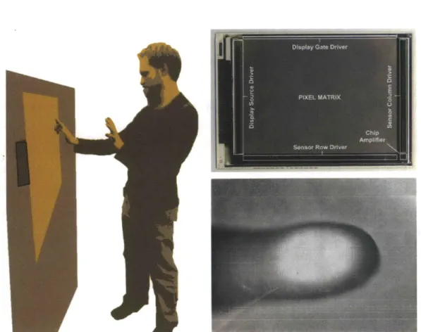
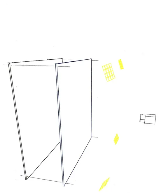
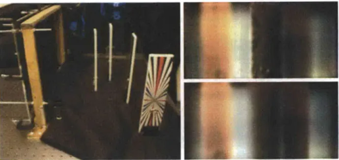
Figure 2-1: Towards a BiDirectional (BiDi) screen for walk-up 3D interaction with flat screens. (Left) A conceptual sketch of public use with direct multi-touch plus non-contact hover gestures. Embedding a large-format optical sensor backplane is becoming possible.
(Right, Top) Emerging LCDs [7] with co-located optical sensors (Right, Bottom) capable of capturing sharp images of fingers in direct contact, but blurred for hovering parts.
2.1.1 Light Sensitive Displays
In work that has deeply inspired the design of the BiDi screen, Sharp and Planar have demonstrated LCD prototypes with integrated optical sensors co-located at each pixel for inexpensive multi-touch interaction. These optical touch screens are the first example of a thin, portable display technology that can measure incident light on a per-pixel basis.
Coarser lighting sensitive displays have been used for a range of purposes prior to this. Some portable electronics, including laptops and mobile phones, use ambient light sensors to adjust the brightness of the display depending on the lighting environment. Nayar et al. [41] proposed creating spatially-selective lighting sensitive displays (LSD) by placing optical sensors within the display bezel and altering the rendered imagery to accurately reflected ambient lighting conditions. Cossairt et al. [10] implemented a light field transfer system, capable of co-located capture and display, to facilitate real-time relighting of synthetic and real-world scenes. Fuchs et al. [17] achieved a passive lighting sensitive display capable of relighting pre-rendered scenes printed on static masks. Unlike their design, the BiDi screen works with directional light sources located in front of the display surface and can support relighting of dynamic computer-generated scenes.
2.1.2 Depth Sensitive and Light-field Cameras
Many depth sensing techniques exist which could be for the purpose of gestural inter-action. Passive optical ranging methods include multi-view stereo [46] and depth from focus [40]. Active optical ranging methods include laser striping [6], time-of-flight cameras (e.g., Canesta's CANESTAVISION chip [23] and 3DV's Z-Cam [24]), depth from defo-cus [52], and structured lighting [45].
A wide variety of passive and active techniques are available to estimate scene depth in real-time. The BiDi screen records an incident light field [32] using a variety of attenuating patterns equivalent to a pinhole array. A key benefit is that the image is formed without refractive optics. Similar lensless systems with coded apertures are used in astronomical
and medical imaging to capture X-rays and gamma rays. Zomet and Nayar [59] describe a lensless imaging system composed of a bare sensor and several attenuating layers, including a single LCD. This system does not capture a light-field, but rather explores the space of modified apertures in camera systems. Liang et al. [34] use temporally-multiplexed
attenuation patterns, also displayed with an LCD, to capture light fields. They use a translated pinhole to capture a light-field. In contrast to the broadband mask approach used in the BiDi screen, this would not be capable of capturing images in realtime. Both Liang et al [34]. and Zoment and Nayar [59] focus on building devices in traditional camera bodies, which are not intended to be coupled with display or used for interaction. Zhang and Chen [58] recover a light field by translating a bare sensor. Levin et al. [31] and Farid [13] use coded apertures to estimate intensity and depth from defocused images. Vaish et al. [50] discuss related methods for depth estimation from light fields. In a closely-related work, Lanman et al. [29] demonstrated a large-format lensless light field camera using a family of attenuation patterns, including pinhole arrays, conceptually similar to the heterodyne camera of Veeraraghavan et al. [51]. I use the tiled-broadband codes introduced in those works to reduce the required exposure time. Unlike Veeraraghavan et al. [51] and Lanman et al. [29], the design presented here exploits a mask implemented with a modified LCD panel. In addition, the BiDi screen uses reflected light with uncontrolled illumination.
Pinholes and masks can be used at other positions in an optical train to achieve different results. For example, a pair of pinhole apertures are used in confocal microscopy to increase contrast and scan a 3D target by eliminating rays that originate from points on the target that are out of focus. Coded aperture imaging, also discussed by Veeraraghavan et al. [51], places a coded mask in the aperture of a traditional camera system to enable deconvolution of focus blur after an image has been captured, or measurement of scene depth, depending on the type of code used.
2.2
Bi-directional Displays
Attempts to create a system with a coincident camera and display have aimed to solve the gaze-direction problem in video chat, described in Section 5.3. One example of such a system is patented by Apple Computer[21], and uses a spinning wheel with transparent and mirrored sections to switch a screen between the optical path of a projector and a camera. Systems that use beam splitters or mechanical time multiplexers typically extend the optical path length of the system significantly. The system described by Apple Computer is not able to measure depth. Another coaxial configuration comes from a second Apple Computer patent [48], describing an LCD screen with an array of conventional cameras behind it, or interleaved between rows of display pixels. This configuration has never been manufactured on a wide scale, and no details have been publicly released by Apple about the performance or other specifications of any actual prototypes that have been built. It should be noted that this device should in theory be capable of capturing the incident light field, though it will not sample it as uniformly as the BiDi screen. Since each of the sensors in the Apple device requires a lens, the portion of the screen occupied by each small camera cannot be used for display causing unpleasant visual artifacts in the displayed image.
Software attempts to simulate the effect of coaxial imaging and display devices for the specific case of video-conference gaze correction[ 11] are fundamentally limited to correcting the specific off-axis imaging problem for which they were designed. Software correction approaches have limitations on the types of images they can correct, and the accuracy of the correction, as there is information lost at the time of capture that cannot be recovered in software.
2.3
Light-fields
One simplification that can often be applied to optical systems is to consider a ray-based light transport system. In the realm of geometric optics, the propagation of light through a system can be described by considering the plenoptic function [2], lumigraph [18], or
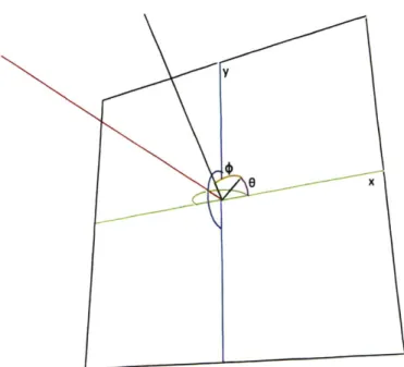
light-Figure 2-2: Single plane parametrization of the light-field. The position of intersection of a ray with the x - y plane, defined above by the x-axis (green) and y-axis (blue), and the
angle in two dimensions Ox (orange), and ,y(purple), describes the set of rays in 3D space.
field[32]. These functions parametrize the radiance of light along rays. The contemporary conception of the light-field was first described in 1996 in the papers by Levoy [32] and Gortler [18]. Earlier references to the idea of capturing a full description of set of rays crossing a plane date to 1908, when Lippmann [35] described a system consisting of an array of pinhole cameras which was able to make measurements of a light-field similar to those recorded by the BiDi screen.
In 3D-space, when occluders are neglected, the light-field can be parametrized with four variables. It is useful to consider two such parametrization. In the case of a single plane parametrization, a ray can be uniquely identified by its point of intersection with a 2D plane, (x, y), and by its angle of intersection with the plane in two directions, Ox and Oy, shown in Figure 2-2.
A second method of parametrize the light-field in 3D-space employs two parallel,
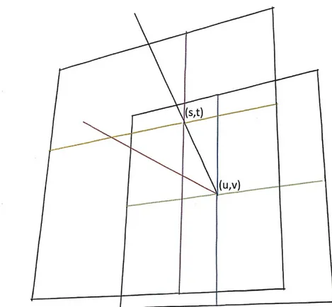
two-dimensional, planes. The ray is uniquely identified in space by its point of intersection with the first plane, (u, v), and its point of intersection with the second plane, (s, t). This also results in a four dimensional function of radiance, as shown in Figure 2-3.
Figure 2-3: Two plane parametrization of the light-field. The position of intersection of a ray with the u - v plane, defined above by the u-axis (green) and v-axis (blue), and the s - t plane, defined above by the s-axis (orange) and t-axis (purple), describes the set of
rays in 3D space.
The concept of a light-field is used for many computer graphics rendering applications, as described by Levoy [33]. In the field of computational photography, there have arisen numerous methods for sampling the light-field generated by real-world objects. For example, Wilburn [54], and others [57], describe arrays of cameras capable of sampling a light-field, and Vaish [49] describes a computer system capable of refocusing the captured light-field in real-time. Ng [42] describes a single, hand-held camera which uses an array of lenses, or lenslets, on top of a sensor to enable a range of light-field sampling patterns. Lenslet arrays have now become a popular way to sample the light-field. Methods that do not employ additional lenses have also been described. Zomet uses an LCD in front of a camera sensor to capture a light field [60]. This design can scan a single transparent pixel across the LCD, effectively time-multiplexing an array of pinhole cameras. A class of light-field sampling devices exists which does not employ lenses and does not rely on time-multiplexing: mask-based light-field photography.
2.3.1 Mask-Based Light-field Photography
Mask-based light-field capture uses a tiled broadband mask offset from the sensor plane to create shifted copies of the light-field frequency spectrum. The principle exploited by this technique is the same one used by AM radio to shift audio-frequency signals (20kHz) to broadcast frequency signals (eg. 1000kHz). For this reason, Veeraraghavan, first to describe the technique, refers to this work as Spatial Heterodyning [51]. The flatland case is depicted in Figure A-2.
Though Veeraraghavan used a lens in their mask-based imaging system, it can be shown that a sensor and mask alone can capture a light-field that is sufficiently band limited. Lanman demonstrates a system that captures a light-field-like quantity without the use of lenses [29]. Lanman et. at. also show the optimality of the tiled-Modified Uniform Redundant Array (MURA) code, for light efficiency.
The BiDi screen builds on the work of Veeraraghavan and Lanman to create a wide-baseline lensless light-field sensor, capable of sampling the light-field generated by reflected light from
an arbitrary scene. The BiDi screen is the first to use a dynamic mask (an LCD screen, in this case) to perform mask-based light-field photography.
Chapter 3
Bidirectional Display Design
It is increasingly common for consumer electronics devices that have the ability to display images to also be able to capture them. Four basic goals motivated the design of the BiDi
screen:
1. Capture 3-D to enable depth and light aware interaction. 2. Prevent image capture from interfering with image display. 3. Support walk-up interaction (i.e., no implements or markers). 4. Allow for mobility and portability.
3.1
Design Parameters
After careful consideration of the related work and possible image capture options, I believe that the approach taken toward the BiDi screen is uniquely positioned to satisfy the above goals. In this section I contrast the chosen approach to other possible methods.
A core design decision was to use optical sensing rather than capacitive, resistive, or acoustic modalities. While such technologies have been effectively used for multi-touch input, they do not allow for 3-D capture and off-screen gestures. Some capacitive solutions permit the
detection of an approaching off-screen finger or hand, but they can not accurately or repeat-ably determine the distance of the approaching object. Nor do any of these technologies support lighting aware interactions.
Optical sensing can be achieved in various ways. In many of the cases of previous work, cameras image the space in front of the display. The result is either a specially crafted environment, similar to g-speak, where multiple infrared cameras are positioned around the user and special gloves with high contrast markers must be worn; or, the display housing becomes large to accommodate the cameras, such as with Microsoft's Surface.
Another issue with using standard cameras is the trade-off between placing them behind, to the side, or in front of the display. If the camera is behind the display, then it will interfere with the backlighting, casting shadows and causing noticeable variations in the display brightness. Han's FTIR sensor, SecondLight, and DepthTouch all avoid this problem by using rear projection onto a diffuser rather than an LCD display, at the cost of increased display thickness. If the camera is located in front of the display or to the side, then it risks being occluded by users. Placing a camera in front of the display is also problematic as it demands a fixed installation-violating the design goals. Cameras could be placed in the bezel, looking sideways across the display, but that would also increase the display thickness and still suffer from user self-occlusion events. A half-silvered beam-splitting mirror, placed at a 45 degree angle to the display surface, could be used to give a side-mounted camera a clear view of the interaction space, but this would both greatly increase the depth of the display and also prevent the user from directly touching the screen.
In contrast, the approach described here is to use a sparse array of photodetectors, located behind the individual display pixels. Because the array is sparse, it will not block much of the light from the backlight and any attenuation will be evenly distributed across the screen. Being behind the display, it does not suffer from occlusions caused by the users. The detector layer can be extremely thin and potentially optically transparent (using thin film manufacturing processes), supporting the goal of portability. These are all design attributes we share with the multi-touch displays being contemplated by Sharp and Planar. However, the display additionally requires a small gap between the spatial light modulating and light
-detecting planes. This gap, combined with the techniques described in Section 3.3, allows for the measurement of the angle of incident light, as well as its intensity, and thereby the capture of 3-D data.
It should be noted that for the purpose of the prototype, I sacrificed the goal of portability in exchange for ease of fabrication with commodity hardware. In particular, I simulated the sparse array of photo detectors by using a diffuser screen imaged by standard CCD cameras from behind.
3.2
LCD Overview
An LCD is composed of two primary components: a backlight and a spatial light modula-tor. A typical backlight consists of a cold cathode fluorescent lamp (CCFL), a light guide, a diffuser, and several brightness enhancing films (BEF). The overall function of these lay-ers is to condition the light produced by the CCFL such that it is spatially uniform and collimated [28]. A key role is played by the backlight diffuser; by randomizing both the po-larization state and angular variation of transmitted and reflected rays, the diffuser greatly increases the efficiency of the backlight, allowing light rays to be "recycled" by reflecting between the various layers until they satisfy the necessary collimation and polarization conditions.
The spatial light modulator of an LCD is composed of three primary components: a pair of crossed linear polarizers and a layer of liquid crystal molecules sandwiched between glass substrates with embedded electrode arrays [56]. The polarizer closest to the backlight functions to select a single polarization state. When a variable electric field is applied to an individual electrode (i.e., a single display pixel), the liquid crystal molecules are reconfigured so that the incident polarization state is rotated. The polarizer closest to the viewer attenuates all but a single polarization state, allowing the pixel to appear various shades of gray depending on the degree of rotation induced within the liquid crystal layer. Color display is achieved by embedding a spatially-varying set of color filters within the glass substrate. To achieve wide-angle viewing in ambient lighting, a final diffuser, augmented
with possible anti-reflection and anti-glare films, is placed between the last polarizer and the viewer.
3.3
Hardware Design
As shown in Figure 3-2, the BiDi screen is formed by repurposing typical LCD components such that image capture is achieved without hindering display functionality. The first step is to exclude certain non-essential layers, including the CCFL/light guide/reflector components, the various brightness enhancing films, and the final diffuser between the LCD and the user. In a manner similar to [29], a large-aperture, multi-view image capture device is created by using the spatial light modulator to display a pinhole array or tiled-broadband mask. The key insight is that, for simultaneous image capture and display using an LCD, the remaining backlight diffuser must be moved away from the liquid crystal. In doing so, a coded image equivalent to an array of pinhole images is formed on the diffuser, which can be photographed by one or more cameras placed behind the diffuser. The backlight display functionality is restored by including an additional array of LEDs behind the diffuser.
One important consideration is that an angle-limiting material or other source of vignetting is critical to achieving image capture using the BiDi screen. In practice, the reflected light from objects in front of the screen will vary continuously over the full hemisphere of incidence angles. However, as I describe in the following sections, the proposed image capture scheme assumes light varies only over a limited range of angles-although this range can be arbitrarily large. An angular-limiting film could be placed in front of the BiDi screen, however such a film would also limit the field of view of the display. In the prototype design, the cameras are placed about one meter behind the diffuser. Since the diffuser disperses light into a narrow cone, the diffuser and cameras act together to create a vignetting effect equivalent to an angle-limiting film.
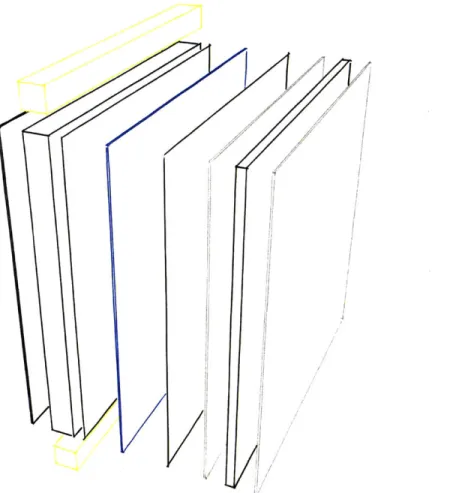
Figure 3-1: Typical LCD components. An LCD is disassembled to display the arrange-ment of the individual optical components. From left to right: (a) rear reflector, (b) the CCFL/light guide illumination source, (c) strong diffuser, (d) brightness enhancing prism film, (e) weak diffuser, (f) reflective rear polarizer (attached with adhesive to liquid crystal layer) (g) the liquid crystal spatial light modulator, and (h) the front polarizer/diffuser (attached with adhesive to liquid crystal layer). While not identical, most modern LCDs have a similar set of layered components.
33
Figure 3-2: This figure depicts two possible BiDi screen configurations. In both configura-tions an LCD spatial light modulator is placed at the front plane (black). In the configu-ration used in the BiDi screen prototype described in Chapter 4, the back plane (blue) is a diffuser, imaged by a camera (gray). In an alternate configuration, the back plane (blue) is
a wide-area sensor, and the camera is not required.
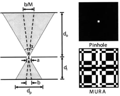
b/M
I I / -I I -b I I b.: / II " dp MURAFigure 3-3: Design of a pinhole camera. (Left) The PSF width b is given by Equation 3.1 as a function of sensor-pinhole separation di, object distance do, and the aperture a. The PSF width is magnified by M = di/do in the plane at do. (Right, Top) A single pinhole comprises an opaque set of 19 x 19 cells, with a central transparent cell. (Right, Bottom) We increase the light transmission by replacing the pinhole with a MURA pattern composed of a 50% duty cycle arrangement of opaque and transparent cells. As described by Lanman et al. [29] and earlier by Fenimore and Cannon [14], this pattern yields an equivalent image as a pinhole.
3.4
Optical Design
The above design goals require sufficient image resolution to estimate the 3-D position of points located in front of the screen, as well as the variation in position and angle of incident illumination. As described by [51], the trade-off between spatial and angular resolution is governed by the pinhole spacing (or the equivalent size of a broadband tile) and by the separation between the spatial light modulator and the image plane (i.e., the diffuser). As with any imaging system, the ultimate spatial and angular resolution will be limited by the optical point spread function (PSF). In this section I analyze the optimization of a BiDi screen for both on-screen and off-screen interaction modes under these constraints for the case of a pinhole array mask. In Section 3.4.2 I extend this analysis to the case of tiled-broadband masks.
3.4.1
Pinhole Arrays
Multi-View Orthographic Imagery: As shown in Figure 3-4, a uniform array of pinhole
images can be decoded to produce a set of multi-view orthographic images. Consider the
orthographic image formed by the set of optical rays perpendicular to the display surface. This image can be generated by concatenating the samples directly below each pinhole on the diffuser plane. Similar orthographic views, sampling along different angular directions from the surface normal of the display, can be obtained by sampling a translated array of points of the diffuser-plane image offset from the center pixel under each pinhole.
On-screen Interaction: For multi-touch applications, only the spatial resolution of the
imaging device in the plane of the display is of interest. For a pinhole mask, this is simply the total number of displayed pinholes. Thus, to optimize on-screen interactions the pinhole spacing should be reduced as much as possible (in the limit displaying a fully transparent pattern) and the diffuser brought as close as possible to the spatial light modulator. This is precisely the configuration utilized by the existing optical touch sensing displays by Brown
et al. [7] and Abileah et al. [1].
Off-screen Interaction: To allow depth and lighting aware off-screen interactions,
addi-tional angular views are necessary. First, in order to passively estimate the depth of scene points, angular diversity is needed to provide a sufficient baseline for triangulation. Sec-ond, in order to facilitate interactions with an off-screen light-emitting widget the captured imagery must sample a wide range of incident lighting directions. As a result, spatial and angular resolution must be traded to optimize the performance for a given application. Off-screen rather than on-Off-screen interaction is the driving factor behind the decision to separate the diffuser from the spatial light modulator, allowing increased angular resolution at the cost of decreased spatial resolution with a pinhole array mask.
Spatio-Angular Resolution Trade-off: Consider the design of a single pinhole camera
shown in Figure 3-3, optimized for imaging at wavelength A, with circular aperture diameter
a, and sensor-pinhole separation di. The total width b of the optical point spread function,
for a point located a distance do from the pinhole, can be approximated as 2.44Adi a(do + di)
b(di, do, a, A) = + (3.1)
a do
: =I
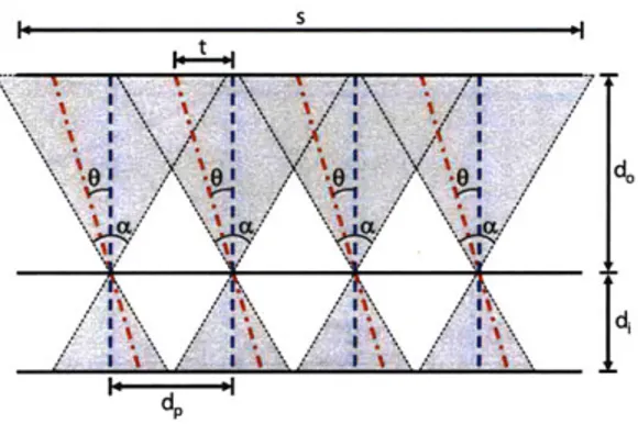
t a\\ /
Figure 3-4: Multi-view orthographic imagery from pinhole arrays. A uniform array of pinhole images (each field of view shaded gray) is resampled to produce a set of orthographic images, each with a different viewing angle 0 with respect to the surface normal of the display. The set of optical rays perpendicular to the display surface (shown in blue) is sampled underneath the center of each pinhole. A second set of parallel rays (shown in red) is imaged at a uniform grid of points offset from the center pixels under each pinhole.
and the geometric projection of the pinhole aperture onto the sensor plane, respectively [20]. If it is assumed that each pinhole camera has a limited field of view, given by a, then the minimum pinhole spacing dp is
dp(di, do, a, A, a) = 2di tan (-) + b(di, do, a, A). (3.2)
Note that a smaller spacing would cause neighboring pinhole images to overlap. As pre-viously described, such limited fields of view could be due to vignetting or achieved by the inclusion of an angle-limiting film. Since, in the proposed design, the number of or-thographic views Nanguar is determined by the resolution of each pinhole image, one can conclude that the angular resolution of the system is limited to the width of an individual pinhole image (equal to the minimum pinhole spacing dp) divided by the PSF width b as follows.
dp(d, do, a, A, a)
Nangular (di, do, a, A, a) = (d, do, a, (3.3)
b(di, do, a, A)
Now consider an array of pinhole cameras uniformly distributed across a screen of width
s and separated by a distance dp (see Figure 3-4). Note that a limiting field of view is necessary to prevent overlapping of neighboring images. As described in Section 3.5.1, the BiDi screen uses a depth from focus method to estimate the separation of objects from the
o 0 . ... ... ... - -- Pinhole Limit S0.5 ... PSF Limit - Combined Limit Cu 0 10 20 30 40 50 Object Distance (cm)
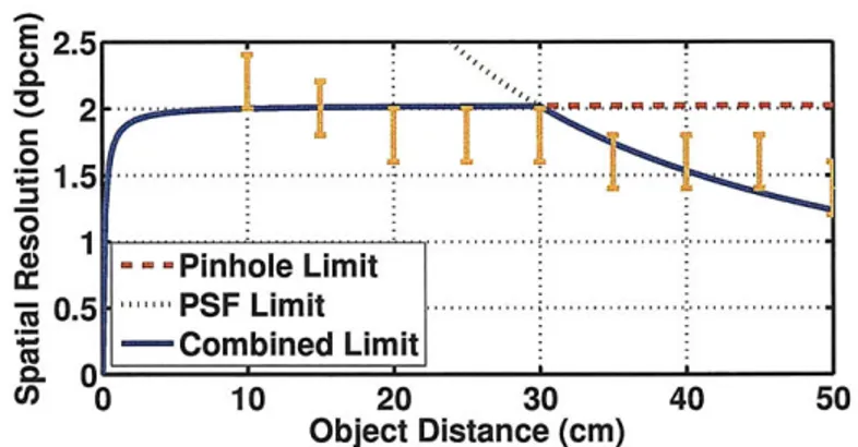
Figure 3-5: Effective spatial resolution as a function of distance do from the display. The effective spatial resolution in a plane at do (given in dots per cm) is evaluated using Equa-tion 3.4. System parameters correspond with the prototype. Orange error bars denote the experimentally-estimated spatial resolution described in Section 4.3. Note that, using either dynamically-shifted masks or a higher-quality image sensor, the spatial resolution could significantly increase near the display (approaching the higher limit imposed by the optical PSF).
display surface. As a result, the system components should be placed in order to maximize the effective spatial resolution in a plane located a distance do from the camera. The total
number of independent spatial samples Nspatial in this plane is determined by the total number of pinholes and by the effective PSF for objects appearing in this plane, and given by
Nspatial (di, do, a, A, a; dp, b) = min d d ) (3.4) where the first argument is the total number of pinholes and the second argument is the screen width divided by the magnified PSF evaluated in the plane at do. Thus, the effective
spatial resolution is given by Nspatial/s. Note that, since the BiDi screen is orthographic,
it is assumed the object plane at do is also of width s.
As shown in Figure 3-5, the effective spatial resolution in a plane at do varies as a
func-tion of the object distance from the pinhole array. For small values of do, the resolution
monotonically increases as the object moves away from pinholes; within this range, the spatial resolution is approximately equal to the total number of pinholes divided by the screen width. For larger values of do, the resolution monotonically decreases; intuitively, when objects are located far from the display surface, neighboring pinholes produce nearly identical images. As described in Appendix A, the sensor-mask (or diffuser-mask) sepa-I~
U . ... : 140 130 120 : 100 90 50 .. 90 35 80 30 . :.. 70 25. 60 25\ 0.1 0. 05 0 0.1 0.05 0 Separation(mm) 20 0.35 03 0.25 1 0.05 Separaon (mm) 20 035 0.3 025 0.2 0.0
Angle (rad) Angle (rad)
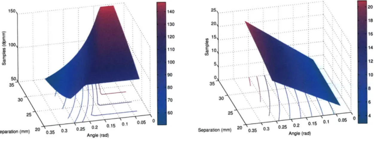
Figure 3-6: (Left) The number of spatial samples measured and (Right) the number of angular samples per pixel measured by varying di and a, with do = 250mm , a = 256 tm, and s = 487.2mm. In the above plots, the mask spacing dp was maximized for a given a. The parameter space in this problem is large, with tradeoffs existing between screen (mask) resolution, sensor resolution, mask pattern size (pinhole spacing), sensor-mask separation, and spatial and angular resolution (ability to resolve depth) and field of view. Note that regions of parameter space above that maximize spatial samples reduce angular samples and vice-versa.
ration is selected to maximize the effective spatial resolution located within 50 cm of the display surface. Note that, in Figure 3-5, the resolution close to the pinhole array drops dramatically according to theory. However, in practice the resolution close to the display remains proportional to the number of pinholes. This is due to that fact that, in the pro-totype, the pinhole separation dp is held constant (as opposed to the variable spacing given in Equation 3.4). Practically, the vignetting introduced by the diffuser and camera's field of view prevents overlapping views even when an object is close to the screen-allowing for
a fixed pinhole spacing.
3.4.2 Broadband Masks
The primary limitation of a pinhole array is severe attenuation of light. For example, in the proposed system a pinhole array is created by separating each pinhole by 18 LCD pixels, both horizontally and vertically. As a result, only approximately 0.2% of incident light reaches the diffuser (or sensor array in an ideal design). To overcome this attenuation,
ii ~.i... i. : ... ; i L-... -. I-. ~ ' i. ;
.,...-..:.
extremely bright external lighting would be required for real-time interaction. Such lighting would significantly impair image display, due to strong glare and reflections. Fortunately, the LCD can be used to display arbitrary 24-bit RGB mask patterns. As a result, the generalized tiled-broadband masks described by Lanman et al. [29] are used. Specifically, the code used is a tiled-MURA code, as shown in Figure 3-3. Each pinhole is replaced by a single MURA tile of size 19x 19 LCD pixels. Because the MURA pattern is binary (i.e., each pixel is either completely transparent or opaque) with a 50% duty cycle, the tiled-MURA mask transmits 50% of incident light. Assuming the cameras have a linear radiometric response, a tiled-MURA mask allows the external lighting to be dimmed by a factor of 180 (in comparison to pinhole array masks).
The heterodyne decoding method of Veeraraghavan et al. [51] is used to decode the diffuser-plane image, yielding orthographic multi-view imagery equivalent to that provided by a pinhole array mask. The use of tiled-broadband codes, however, does require additional computation to decode the diffuser-plane image and introduces additional noise from the decoding process. Note that the spatio-angular resolution trade-off for such tiled-broadband codes are similar to those described in the previous section for pinhole arrays-yielding a multi-view orthographic image array with similar spatial and angular sampling rates. Addition details on such design issues are provided in Appendix A.
3.5
Gesture Detection
3.5.1 Depth Extraction
As described in Chapter 2, there are a wide variety of methods to passively estimate depth from multi-view imagery. The BiDi screen employs a depth from focus method inspired by [40]. In their approach, a focal stack is collected by focusing at multiple depths within the scene. Afterwards, a per-pixel focus measure operator is applied to each image in the focal stack, with the assumption that each image patch will appear with highest contrast when the camera is focused at the depth of the patch. In the implementation described
in Chapter 4 a simple smoothed gradient magnitude focus measure was used. Finally, a coarse depth map can be obtained by evaluating the maximum value of the focus measure for each pixel. While modern depth from focus/defocus methods include more sophisticated focus operators, the approach used here can easily be evaluated in real-time on commodity hardware (see Chapter 4).
In order to obtain the set of refocused images (i.e., the focal stack), I apply methods from synthetic aperture photography [50]. As shown in Figure 3-4, when considering the intersection of the optical rays with a plane at distance do, each orthographic view, whether captured using pinhole arrays or tiled-broadband codes, is translated from the central view by a fixed amount. For an orthographic view rotated by an angle 0 from the display's surface normal, the translation t(0) will be given by
t(do, 0) = do tan(0). (3.5)
In order to synthetically focus at a display do, I follow the computationally-efficient ap-proach of Ng [43]; rather than directly accumulating each orthographic view, shifted by
-t(do, 0), the Fourier Projection-Slice Theorem is applied to evaluate refocused images as
2D slices of the 4D Fourier transform of the captured light field. Typical refocusing results are shown in Figure 3-7. Because the refocusing operation is performed on a two-times unsampled grid, the process achieves a small degree of super-resolution through refocusing. The results shown indicate that web-cam quality images are possible from a device matching the specifications of the prototype constructed (See Chapter 4).
3.5.2 Hand Tracking
Hand tracking is performed using the depth map described in the previous section as input. The OpenCV blob-tracking librariy is used to segment regions of low distance values in the depth map corresponding to hands from the rest of the depth map. The Mean Shift method
[9], combined with an automatically updated foreground mask was found to give the best results. The OpenCV library referes to this as the MSFG method. A Kallman filter, provided
Figure 3-7: Synthetic aperture refocusing with orthographic imagery. (Left) A scene com-posed of three textured cards (center card has a printed resolution test chart shown facing camera on the left). (Right) Synthetically refocused images at a distance do of 10 cm and 15 cm shown on the top and bottom, respectively.
by the OpenCV blob-tracking library, was used to filter the resulting position data.
The method described here has some disadvantages over other types of gesture tracking. It cannot determine the pose or orientation of the hand, only the position over the screen. This method would likely be used as the first step in a more sophisticaed gesture tracking pipeline. The method has the advantage that it easily runs in realtime, and was already impleneted in free software. The method works sufficiently well in the prototype described in Chapter 4 to drive the demonstrations described in Chapter 5.
3.5.3 Touch Estimation
There exist a wide variety of methods for extracting touch events from a device like the BiDi screen. It would certainly be possible to cover the surface of the BiDi screen with a resistive or capacitive touch screen. However, this would lead to increased complexity and cost. To reduce cost and complexity, it will be most efficient to use the optical sensor of the BiDi screen to locate touch events. A rudimentary method of touch estimation is to find the average depth value of each blob used in hand tracking (Section 3.5.2), and determine touch events when this average value falls below a threshold.
For a detected blob with mean position (x, y) in the depth map, ROI R, and number of
non-zero elements, d, contained in R, NR, the mean depth value, D, is given by
D= di (3.6)
icR
A touch is detected when D < Dthr, where Dthr is a depth threshold that can be tuned. It should be noted that a gap exists between the front of the LCD and the transparent acryllic sheet used to protect the surface of the LCD from direct touches. This gap prevents fingers that touch the screen from occluding all ambient lighting.
The above approach is useful in its extreme simplicity, and worked sufficiently well for the prototype discussed in Chapter 4. However, it has significant disadvantages. The center of a detected blob is rarely aligned with the extended finger performing the actual touch, meaning that this method further reduces the resolution of the depth map, allowing for only very course touch detection. Also, using this method, touch events are dependant not only on the distance of the tip of a finger to the surface of the screen, but also on the distance of the rest of the hand. This is undesireable, since it is an unexpected result for users (see the discussion of user experience in Section 4.4).
A plausibile extension to the method described here would resolve the above issues without incurring significantly more processing cost. Once candidate blobs have been selected for touch detection using the threshold applied to Equation 3.6, the raw modulated light field data can be used as input to a touch detection algorithm inspired by touchlib (a library for creating multi-touch interaction surfaces by tracking blobs of reflected light) or similar libraries. Without the influence of the mask function, which can be removed with a low-pass filter, the user's hand is effectively viewed through a diffuser. This is consistent with many of the optical touch detection approaches described in Chatper 2. The depth map blob could provide an ROI into the raw data to further reduce computation time and spurious results.
Chapter 4
Prototype: Construction and
Performance
4.1
Implementation
4.1.1
Hardware
As shown in Figure 3-2, the prototype BiDi screen was constructed by modifying a Sceptre X20WG-NagaII 20.1 inch LCD with a 2 ms response time. The spatial light modulator was separated from the backlight, and the front diffuser/polarizer was removed. The weak diffuser was retained from the backlight and placed at di=2.5 cm from the liquid crystal layer on the side opposite the user. The front polarizer of the LCD was replaced with a linear polarizing polyvinyl alcohol-iodine (PVA) filter placed in direct contact with the diffuser. Commercial LCD screens typically combine the front polarizer with a diffusing layer, as was done on the X20WG. A diffuser in the plane of the spatial light modulator would interfere with the image capture mechanism. In order to easily mount the replacement polarizer on the correct side of the screen, the LCD was mounted backwards, so that the side typically facing the user was instead facing inward towards the backlight. The backlight functionality was restored by replacing the CCFL/light guide/reflector component with a
set of 16 Luxeon Endor Rebel cool white LEDs, each producing 540 lumens at 700 mA, arranged evenly behind the LCD. The LEDs were strobed via the parallel port to allow them to be shut off during the capture frame.
A pair of Point Grey Flea2 video cameras were placed 1 m behind the diffuser, each imaging approximately half of the diffuser while recording a 1280x960 16-bit grayscale image at 7 fps. For some interaction sessions, the cameras were operated in 8-bit grayscale mode. The camera shutters were triggered from the parallel port in order to correctly synchronize image capture with the LCD frame updates and LED strobing. Image capture and display was performed on an Intel Xeon 8 Core 2.66 GHz processor with 4 GB of system RAM and an NVIDIA Quadro FX 570 graphics card. The refocusing, depth estimation, and lighting direction estimation pipeline was capable of processing raw imagery at up to 7.5 fps. The prototype was constructed on a standard optical bench, which provided a surface to precisely mount each of the elements of the optical stack described above. A custom frame was constructed to hold the naked LCD screen. The frame consists of two wooden beams bolted vertically to the optical bench. Slits were cut into the inner faces of the beams, allowing the screen to be slid in between them. Bolts were run through the beams in the direction into the plane of the LCD screen. These bolts were used to suspend the remainder of the optical stack at the desired distance from the LCD. A protective clear acrylic sheet was suspended between the user and the LCD screen to protect the delicate rear-polarizer from touches. This protective layer serves a double purpose, also preventing the LCD from being fully shaded from external lighting when a user is in contact with the screen.
External lighting was provided by overhead halogen lamps when the MURA code was used. Capturing images with a pinhole mask required an additional halogen stage lamp placed above the region in front of the LCD. This lighting was sufficient for imaging gestures and objects placed far from the display (e.g., the textured cards in Figure 3-7).
Both pinhole arrays and tiled-MURA codes were displayed on the LCD, with the latter used for real-time interaction and the former for static scene capture. Both the pinholes and MURA tiles repeated every 19 x 19 LCD pixels, such that dp = 4.92 mm with a square
pinhole aperture of a = 256 pm. Following the derivation in Section 3.4, the acquired light field had a maximum spatial resolution of 88 x 55 samples (in the plane of the LCD) and an angular resolution of 19x 19 samples spanning ±5.6 degrees perpendicular to the display surface. The actual spatial resolution recorded was 73 x 55 samples, due to redundant measurements in the area of the screen viewed by both cameras. While narrow, this field of view and the limited spatial resolution was sufficient to provide robust refocusing and depth estimation (see Figures 3-7 and 4-5).
During interactive operation, three frames were sequentially displayed: a MURA code, and two display frames. The screen was refreshed at an average rate of 21 Hz and images were captured by the cameras each time a MURA frame was displayed. This results in the 7 fps capture rate described above. For static scene capture a sequence of two frames, a pinhole mask, and a "black" background frame were captured. Because timing was unimportant in a static scene, the frame rate of the pinhole capture sequence was adjusted according to scene lighting to allow for a sufficiently long camera exposure time. Background subtraction was used to mitigate the effects of the limited contrast achieved by the spatial light modulator for large incidence angles [56].
4.1.2 Software
As described above, the BiDi screen is controlled by a desktop computer running Windows XP 64-bit. The software controlling the BiDi screen, known as bidicam, was written in C++ and compiled with Microsoft Visual C++. The rendering and image capture from the cameras are controlled from a single class called Video. The graphics generated by the BiDi screen are rendered in OpenGL [47]. The Glut toolkit [27], provided by NVIDIA, is used to provide the rendering context for OpenGL, and the main loop for the bidicam application. Images are read from the cameras using the Point Grey flycapture library, version 2.
A Glut timer callback function orchestrates the backlight, camera triggering, and screen updates. The cameras and lights are both triggered by a signal sent from the parallel port