Biodegradation of Chlorinated Solvents in the Sediment of Ashumet Pond, Cape Cod, MA
Jeri A. Champion
S.B., Chemical Engineering (1997) Massachusetts Institute of Technology
Submitted to the Department of Civil and Environmental Engineering in Partial Fulfillment of the Requirements for the Degree of Master of Engineering in Civil
and Environmental Engineering at the
Massachusetts Institute of Technology
June 1998
©1998 Massachusetts Institute of Technology All rights reserved.
Signature of Author ...
Department of C1il
... ... ... .... .. °°°, ... and Environmental Engineering
May 13, 1998 Certified by ... Professor of Civil Accepted by ... Chairman, Departmental
JUN
021998
Harold F. Hemond and Environmental Engineering Thesis SupervisorJoseph M. Sussman Committee on Graduate Studies
En&
UBRARIESBiodegradation of Chlorinated Solvents in the Sediment of Ashumet Pond, Cape Cod, MA
Jeri A. Champion
Submitted to the Department of Civil and Environmental Engineering on May 13, 1998, in Partial Fulfillment of the Requirements for the Degree of Master of
Engineering in Civil and Environmental Engineering
ABSTRACT
This study outlines the fate and transport of chlorinated aliphatic hydrocarbons discharging from the Ashumet Valley plume through the sediment of Ashumet Pond. The biodegradation of perchloroethene (PCE) and trichloroethene (TCE) is of particular importance because of their potential conversion to vinyl chloride, a rather more toxic substance, as a degradation product. By incorporating existing data into sediment and water column mass transport models, it is possible to predict the significance of biodegradation of these compounds.
Biodegradation has been shown to be a significant cause of attenuation of PCE and TCE in Ashumet Pond sediment. Due to volatilization and huge dilution effects, however, these contaminants and the major degradation product, cis-1,2-dichloroethene (cis-1,2-DCE), remain undetected in the water column.
Thesis Supervisor: Harold F. Hemond
Acknowledgments
I would like to take the opportunity to thank the following individuals, without whom this project would not have been possible:
Prof. Harry Hemond, my thesis advisor, for his accurate technical guidance,
careful advice, and a sympathetic ear.
Dr. Pete Shanahan, my project group advisor, for his endless patience and
support, as well as the occasional poke in the right direction.
Bruce Jacobs for his suggestions and upbeat attitude.
Prof. Dave Marks for believing I could accomplish the impossible.
Amy Rolfs, Bina Indelicato, Conny Mitterhofer, and Sharonda Bridgeforth,
my project group, for their help, ideas, and camaraderie.
Stuart Levine, my devoted fiance, for being there.
Last but certainly not least, my parents, Joseph and Leonila Champion, without whose help and encouragement I could never have made it this far.
Table of Contents
1. Introd uction ... ... 6
1.1 Overview of problem and objectives ... ... 1.2 N atural attenuation ... 9
2. The Massachusetts Military Reservation...10
2.1 Hydrogeology and topography ... 10
2.2 C lim ate ... ... . ... 13
2 .3 H isto ry ... 13
2.4 Ground-water contaminant plumes ... 15
2.4.1 Chemical Spill 10 (CS-10) ... 16 2.4.2 Storm D rain 5 (SD-5) ... 17 2.4.3 Ashumet Valley ... 18 3. Ashumet Pond... ... 20 3.1 C haracteristics ... ... .. 20 3.1.1 Hydrogeology ... ... 20 3.1.2 Geochemical characteristics ... ... 20 3.1.3 Land use ... ... ... 21
3.2 The road to eutrophication ... 21
4. Reductive Dechlorination ... ... 22
4.2 M icrobial requirem ents ... 25
4 .3 K inetics ... ... 26
5. Sediment Model ... ... 29
5.1 Hydrogeological considerations ... ... 30
5.2 Mass transport processes ... ... 30
5.2.1 Advection with sorption ... 30
5.2.2 D ispersion ... ... ... 32
5.2.3 V olatilization ... ... ... 32
5.2.4 Biodegradation ... 32
5.2.5 Mass transport results ... ... 33
6. Water Column Model... ... 36
6.1 W ell-M ixed M odel ... 37
6.2 Stratified Pond M odel ... .40
7. Discussion and Recommendations ... 43
7.1 Sedim ent M odel Results ... .43
7.2 Water Column Model Results ... 44
7.3 Possibilities for Future Investigation ... 44
1.
Introduction
1.1 Overview of problem and objectives
Chlorinated solvents are some of the most common subjects of environmental remediation projects today, particularly in ground water. They were commonly used as petroleum additives and degreasers, chosen for their relative noninflammability compared to nonhalogenated hydrocarbons, and their improper disposal was often overlooked. Unfortunately, these compounds are more toxic and more persistent in the environment than the hydrocarbons previously used (Rodricks 1992). Spilled, often deliberately, onto the ground, these dense non-aqueous phase liquids (dNAPLs) might evaporate, sorb onto organic matter in the soil, or form streams of organic contaminants that would spread with the flow of ground water over future decades. These ground-water contaminant plumes would migrate until being caught up at discharge points, often wells or bodies of surface water. During their travels, chlorinated solvents undergo attenuation through various processes, one of which is biodegradation.
Through naturally-occurring chemical and biological processes, these
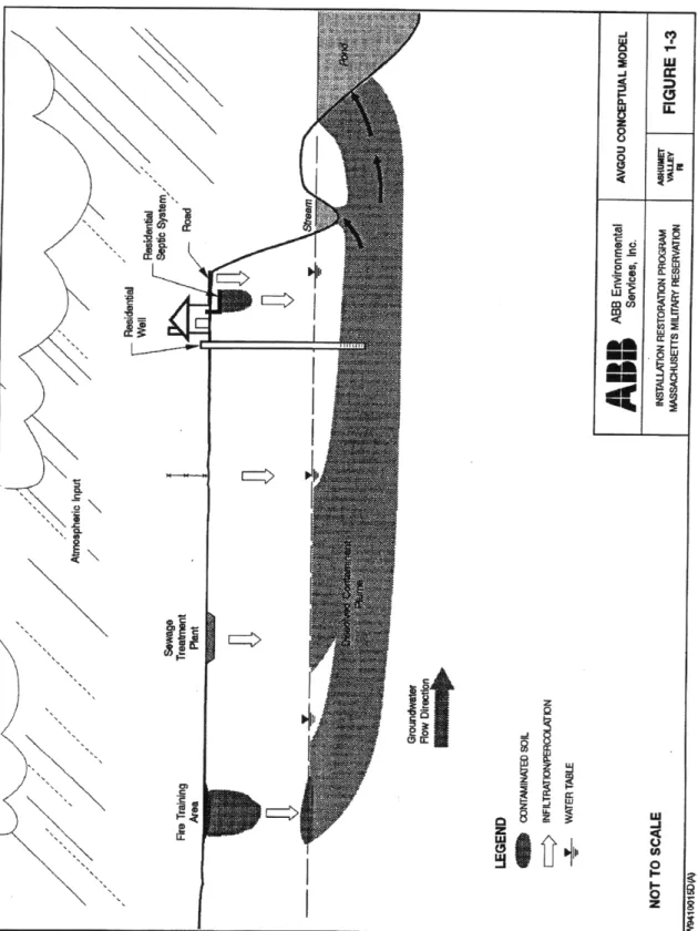
substances may be converted into other, possibly more harmful, compounds. This conceptual model is depicted in Figure 1.1.
i
lit
C: Q. z Wuh
o=
B
Figure 1.1. Conceptual Model of Contaminant Transport. (ABB 1995) At the Massachusetts Military Reservation (MMR) Superfund site in western
Cape Cod, Massachusetts, over 78 disposal sites have been identified, nearly half of which require further remedial action. Many of these plumes contain chlorinated solvents from chemical spills, fire training exercises, leaking underground tanks, and other sources. Unfortunately, as the MMR is situated atop the water-table mound for the Cape, and because many years passed before these plumes were identified, the contamination has had ample opportunity to spread outside of the MMR boundary and leach into the unconfined aquifer, which provides the major source of drinking water for the surrounding area. Much of the remediation effort is therefore directed toward the Cape Cod aquifer. The area, however, is also pitted with many small bodies of surface water, kettle holes left from the last glacial retreat, into which ground water discharges. It is possible that chlorinated hydrocarbon contaminants are currently leaching into these ponds and wetlands, and through naturally-occurring chemical and biological processes, being converted into other, possibly more harmful, compounds. This is the basic problem with which this thesis is involved.
During their travels, chlorinated solvents undergo attenuation through various processes, one of which is biodegradation. In considering the biodegradation of chlorinated solvents that may have migrated from the nearby Massachusetts Military Reservation to the sediment of Ashumet Pond on Cape Cod, several immediate questions need to be answered:
* Which chlorinated solvents are present?
* What are the other possible sources and sinks (aside from biodegradation) of these solvents, and what are their magnitudes? * In what forms do these solvents reside within the pond sediments? * What are the primary factors that influence the kinetics of
biodegradation?
* What are the intermediate and end products of biodegradation?
* What is the time frame for biodegradation? What is the residence time of contaminants within the sediment?
* How does biodegradation otherwise influence the environment within and around the sediment?
* What are some feasible methods of enhancing the process?
1.2 Natural attenuation
Natural attenuation of ground-water contaminants has recently been a focus of remediation technology research. Natural attenuation is the set of naturally occurring processes, including advection, dispersion, dilution, volatilization, chemical reaction, sorption, and biodegradation, that break down or reduce the concentration of contaminants present in a system. Rather than being a "do nothing" approach to remediating contaminated sites, natural attenuation relies on the verification and monitoring of the natural in situ remediation processes. Compared with other technologies, it is inexpensive, nonintrusive, generates no remediation waste, does not suffer the limitations of equipment and labor common to other alternatives, and can be very effective when used in conjunction with other techniques. On the other hand, it can be subject to natural or anthropogenic changes in hydrogeologic conditions, can be complicated by the heterogeneity of the system involved, requires long residence times, and can produce intermediates that are more toxic than the original contaminants (e.g., vinyl chloride from trichloroethene and perchloroethene) (Wiedemeier 1996). Of course, as with any proposed plan of remediation, natural attenuation must adhere to state and federal standards.
Natural attenuation may nevertheless be occurring in a contaminated ground-water system, even if it is dismissed as an infeasible remediation option. For this reason, investigation into natural attenuation processes is not purely academic. An accurate accounting of contaminant fate and transport, even if a remediation
system is already in place, must include an assessment of ongoing attenuation processes. Of the processes involved in natural attenuation in ground water, biodegradation may be one of the most important, yet it remains perhaps the least understood.
In order to assess the possible impact of natural attenuation on a contaminated site, more research into biodegradation as a major contributor is required. Given sufficient information regarding the contaminants and hydrology of a system, it may then be possible to model more accurately contaminant transport through the system, taking into account all mechanisms of attenuation, including biodegradation. Only then can the full effect of natural attenuation, for good or for bad, be properly estimated.
2. The Massachusetts Military Reservation
2.1 Hydrogeology and topography
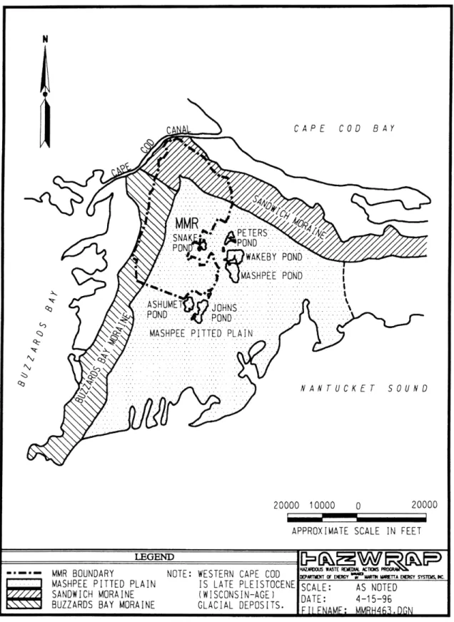
The geology of western Cape Cod was shaped during the Wisconsin period, 85,000 to 7,000 years B.P. (Before Present), of the Pleistocene epoch, with the advance and retreat of two glacial lobes that resulted in glaciofluvial sedimentation. To the north and west, the Buzzards Bay and Sandwich Moraines are composed mostly of glacial till. South is the Mashpee Pitted Plain, an outwash plain containing poorly sorted fine- to coarse-grained outwash sands overlying finer-grained till and marine or lacustrine sediment. This lower layer of fine sediment has a hydraulic conductivity that is as much as five times less than that of the upper outwash layer, so that ground-water flow occurs mostly through the upper layer. Seepage velocity within the sand and gravel outwash is estimated between 1 and 4.6 feet per day, with virtually no vertical flow. The entire plain is dotted with numerous kettle holes, bodies of water that resulted when large blocks of glacial ice, embedded in the sediment, melted. Mostly ground-water recharge and runoff maintain these ponds. About 45% of
precipitation infiltrates to the water table, which is about 21 inches annually; net recharge to the ponds from precipitation is approximately 18 inches each year (ABB 1995). Ground-water flow is south or southeast through the unconfined aquifer, which is known as either the Westcape Aquifer or as the Sagamore Lens of the Cape Cod Aquifer. The equilibrium recharge mound is located north of Snake Pond.
N
CA \ CAPE COD BAY
NAR ~
PETERS.-..-.. , WAKEBY POND
MASHPEE POND
.M . .ASHPEE PITTED PLAIN.... .... ... ... . .HS... ... ... ....
4' ' NANTUCKET SOUND
20000 10000 APPROXIMATE SCALE IN 0 FEET20000
..
MMR BOUNDARY NOTE: WESTERN CAPE COD D'.*' W...cy.s.s.. MASHPEE PITTED PLAIN IS LATE PLEISTOCENE SCALE: AS NOTED
SANDWICH MORAINE (WISCONSIN-AGE) IDATE 4-I 5-96
BUZZARDS BAY MORAINE GLACIAL DEPOSITS. AE: - 6
_ _ __\_ __ .. In FI FNAMF: MM...
The topography of the area can be characterized as a broad, flat, glacial outwash plain, dotted by kettle holes and other depressions, with marshy lowlands to the south, and flanked along the north and the west by recessional moraines and hummocky, irregular hills. Remnant river valleys cross the Mashpee Pitted Plain from north to south, while to the north and west the Buzzards Bay and Sandwich Moraines lend a higher degree of topographic relief.
2.2 Climate
The climate on the western Cape is classified as humid continental. Winds come from the northwest from November to March and from the southwest the rest of the year, with speeds averaging 9 mph (14.5 km/hr) from July to September and 12 mph (19.3 km/hr) from October to March. Average rainfall is approximately 47.8 inches annually, with June the driest month of the year. February is the coldest month, averaging 23 to 389F (-5 to 32C); July is the warmest, with temperatures ranging from 63 to 789F (17-269C) (ABB 1995).
2.3 History
The MMR complex, located near the towns of Bourne, Falmouth, Mashpee, and Sandwich, comprises about 22,000 acres on the Mashpee Pitted Plain. It has hosted many military groups since the 1930's, with the most activity occurring from 1940-1946 by the U.S. Army and 1955-1972 by the U.S. Air Force. Nearby land is used for residential areas; commercial and industrial uses such as sand and gravel pits, landfills, and wastewater treatment; cultivation of agricultural products such as blueberries, cranberries, and vegetables; and a wide variety of recreational purposes, especially on the ponds. The area is also home for many vertebrate and invertebrate species, including several state-listed rare and endangered species, whose habitats include the southern cranberry bogs and the Crane Wildlife Management Area.
often chlorinated solvents, were commonly used and disposed in landfills or drywalls, or burned at firefighter training areas. Unfortunately, the base's location so near to the ground-water recharge mound amplified the impact of these toxic spills, causing them to form large plumes of contamination. Today, 78 contaminated sites have been identified; the area was added to the U.S. Environmental Protection Agency's (EPA) National Priority List (Superfund) in 1989. Nearly half of these sites require no further action; the Installation Restoration Program (IRP) is administering the remaining sites.
2.4 Ground-water contaminant plumes
Figure 2.2. Massachusetts Military Reservation ground-water plume map. (MMR 1997)
Ashumet Pond is located directly south of the MMR, as seen in Figure 2.2. Of the plumes originating within the boundaries of the reservation, three may have a potential impact on the pond: Chemical Spill 10 (CS-10), Storm Drain 5 (SD-5), and the Ashumet Valley plume. These ground-water plumes all contain
tetrachloroethene (PCE) and trichloroethene (TCE) as primary contaminants and may additionally contain 1,2-dichloroethene (1,2-DCE), which is also a potential breakdown product of PCE and TCE. PCE and TCE are classified as suspect human carcinogens; DCE has not been classified as to human carcinogenicity. These three chlorinated solvents are denser than water, volatile, and somewhat soluble. Another potential breakdown product, vinyl chloride, is a known human carcinogen that particularly targets the liver. Vinyl chloride is rather volatile and is less soluble than the other chlorinated hydrocarbons under consideration. Some physical properties of these chlorinated aliphatic hydrocarbons are listed in Table 2.1 below.
Table 2.1. Basic properties of chlorinated solvents.
(Adapted from Hemond and Fechner, 1994)
TCE 131.39 1.46 1000 0.08 0.42 2.42 cis-1,2-DCE trans-1,2-DCE Vinyl chloride 96.94 96.94 62.50 1.28 1.26 0.91 3500 6300 90 0.26 0.45 3.4 0.25 0.23 99 2.4. 1 Chemical Spill 10 (CS-10)
The primary source for the CS-10 ground-water plume is the former missile site and the current Unit Training Equipment Site (UTES), eastern perimeter of the MMR. This plume, composed mainly of PCE,
1.86 2.06 0.60 BOMARC near the TCE, and
1,2-DCE, travels with the ground-water flow southeast toward Ashumet Pond. Maximum concentrations of PCE in the western lobe reach 400 gg/L, and concentrations of TCE in the eastern lobe reach as high as 3200 gg/L (Jacobs 1997). The plume is approximately 17,000 feet (5.2km) long, 4,000 feet (1.2km) wide at the maximum, and is a maximum of 140 feet (43m) thick. CS-10 is on average over 120 feet (37m) below ground level and 60 feet (18m) below the water table.
A number of possible contributors to the CS-10 plume, including over 180 former waste storage and disposal sites located above the plume, have been removed. The current proposed remediation plan includes an extraction, treatment, and reinjection (ETR) well fence along Sandwich Road, upgradient of the leading edge of the plume along the northwest boundary of Ashumet Pond, and is expected to capture 98% of the contaminants within the plume (MMR 1997).
2.4.2 Storm Drain 5 (SD-5)
Storm Drain 5, which received runoff from various military and industrial activities on the reservation, is the source of this plume, whose dominant components are PCE, TCE, and 1,2-DCE. The ground-water plume, included in Figure 2.2 above, extends south between Ashumet and Johns Ponds, where Ashumet Pond recharges into Johns Pond. SD-5 is approximately 10,000 feet (3.0km) long, 1750 feet (530m) wide, and 20-100 feet (6.1-30.5m) thick, extending
50-130 feet (15-40m) beneath the ground surface.
Treatment schemes for the northern portion of the plume include an ETR well system using granular activated carbon to treat the effluent. The southern portion will use recirculating wells rather than ETR well treatment due to the complexity of the hydrogeology between Ashumet and Johns Ponds (MMR 1997).
2.4.3 Ashumet Valley
The sources of the Ashumet Valley plume include the sewage treatment plant for the MMR and the former fire training area (FTA-1). Activities at the fire training area involved the release of large quantities of fuel onto the ground in unlined pits, which were then ignited and put out using chemical extinguishers. As a result, fuels and additives leached into the ground water. The plume has two zones: an anoxic zone, where iron and manganese are in their soluble, reduced forms; and a suboxic zone, in which iron and manganese are in their insoluble, oxidized forms (Figure 2.3). Besides the inorganic nutrients in the sewage plume, primary contaminants include PCE, TCE, and an aviation fuel additive, dibromoethene (EDB), with approximate maximum concentrations of 88 ppb, 52 ppb, and 0.1 ppb, respectively (MMR 1997). Sand and gravel deposits comprising the matrix in this plume have estimated hydraulic gradients at 380 ft/day, with a porosity of 0.39 (Walter et al. 1996). Due to the availability of nutrients, the large potential contact zone between the plume and the pond sediment, and the geochemical characteristics in this plume, the Ashumet Valley plume was chosen as the focus of the fate and transport model.
3. Ashumet Pond
3.1 Characteristics
3. 1.1 Hydrogeology
Ashumet Pond, like most of the other water bodies on the Mashpee Pitted Plain, is a kettle hole pond formed from a buried block of ice left over from the last glacial retreat. After the ice melted, the overlying sediment collapsed, forming what is called a collapse structure. Ground-water flow recharges the pond from the upgradient side (north and northeast) and discharges downgradient (south and west), toward Johns Pond and areas south of Ashumet Pond. Material surrounding the pond is composed of primarily well- to poorly-sorted, fine- to coarse-grained sand with fine- to coarse-grained gravel. Collapse structures typically have geological features that differ from those of the surrounding aquifer, with deeper contact between medium and fine sand and silt (Walter et
al. 1996). The pond-bottom sediment is predominantly gray silty or clayey sand,
with approximately 16-70% silt or clay. Hydraulic conductivity is high near the shore but falls off rapidly in the sediment, with a pond-bottom hydraulic conductivity measured from 2 to 235 feet/day (0.61 to 72 m/day). Seepage flux is non-homogeneous, with most flux occurring relatively unimpeded near the shore. Inlets include a minor drainage ditch from an abandoned cranberry bog to the north; net surface flux (precipitation less evaporation) averages 50,000 ft3/year (1420 m3/year) (Jacobs Dec. 1997).
3. 1.2 Geochemical characteristics
The littoral waters of Ashumet Pond are in the oxidizing regime, with pH ranging from 5.5-6.5 (Jacobs 1997). As ground-water flow discharges to the pond, dissolved iron and manganese from the anoxic environment of the Ashumet Valley plume become oxidized and precipitate out of solution. This process is evident in the black coating of the rocks along the western edge of the pond.
Along the bottom of the pond, pH and dissolved oxygen (DO) levels increase, ranging from 8.1 to 9.6 and 7.3 to 10.2, respectively (Jacobs 1997). The low alkalinity (Alk) of the pond translates into a low buffer capacity; small changes in acid-base interactions can lead to larger changes in pH. On the downgradient side, the pH equilibrates with that of the unconfined aquifer as the pond water
discharges into the ground water.
All of these factors are variable depending on the time of day and the season. Increased biological activity in the summer and in the late afternoon causes the pH to rise. During the day, as carbon dioxide is consumed, the buffer capacity declines and pH increases; the opposite occurs in the evening. In addition, variations in precipitation levels can cause large variations in the chemistry of the pond, particularly as the result of atmospheric deposition.
3.1.3 Land use
The Ashumet Pond watershed is largely undeveloped. Seasonal and year-round housing surrounds the pond, except along the northern edge. An abandoned cranberry bog is located to the north. The pond itself is primarily used for a variety of recreational purposes, including fishing, boating, and swimming.
3.2 The road to eutrophication
Since 1969, Ashumet Pond has experienced increased nutrient levels, mainly as a result of over-fertilization of the surrounding area (Walter et al. 1996). This phenomenon has caused concern that the pond might become eutrophic, leading to a simplification of the structure of the aquatic community and eventually loss of fish species and reduced stability of the system. The small size and shallow depth of kettle hole ponds generally causes them to be more vulnerable to changes in water quality as a result of a greater input of nutrients. As the wetland ages, further growth would foster the buildup of sediment, and gradually the pond would become a bog.
During the summer this process is particularly exacerbated by the stratification of the pond, when the hypolimnion is apt to become anoxic. Variations in the trophic state of a pond can be large, depending on short- and long-term variabilities in the environment.
In 1969, studies conducted at Ashumet Pond characterized it as oligotrophic to mesotrophic. Fifteen years later, the pond was classified as mesotrophic. It is possible that this difference is due more to changes in the classification criteria than to environmental factors (Walter et al. 1996). However, anthropogenic nutrient sources, including the Ashumet Valley sewage plume, residential septic systems, and fertilizer runoff, are significant as compared to natural sources such as input from rainfall and biological processes, including excretion and death, occurring in the pond.
If the pond is becoming eutrophic, this process may lead to an excess of available substrates for bacterial growth; anoxic conditions, which are required for the biodegradation mechanism; and electron donors for the process of reductive dechlorination, by which biodegradation in sediment would be most likely to occur. Biodegradation will not occur unless the geochemical status of the sediment is conducive to the mechanism; if conditions are right and the necessary bacteria are present, the mechanism may proceed. In order to determine whether biodegradation is possible, information is required regarding whether the limiting conditions of the mechanism are met.
4. Reductive Dechlorination
4.1 Mechanism
Biodegradation reactions involve an oxidation-reduction (redox) reaction taking place by way of biological pathways in an organism. Mechanisms involving chlorinated aliphatic hydrocarbons in particular may take one of three paths. The contaminant may be used as a primary substrate, or electron donor; or it may be used as an electron acceptor, as in reductive dechlorination. The contaminant
may alternatively undergo cometabolism by the organism, under which conditions the contaminant produces no benefit to the microorganism and may even be toxic to it. Cometabolism is most likely to occur under aerobic conditions and degrades the least-chlorinated compounds the fastest.
Under anaerobic conditions, reductive dechlorination is the fastest of these three possible pathways, degrading the widest variety of chlorinated aliphatic
hydrocarbons. Electron donors under these circumstances may include
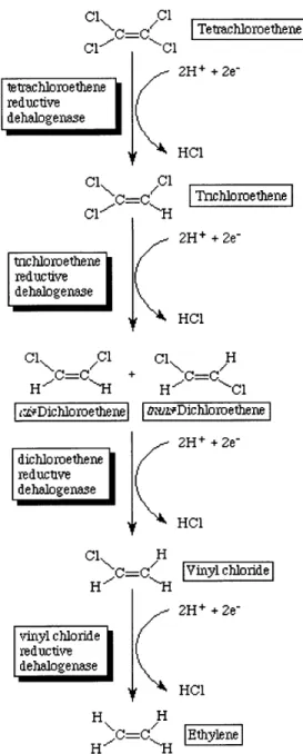
ubiquitous organic matter, other contaminants such as fuel hydrocarbons, and other manmade organics. One study (DiStefano et al. 1992) showed that the wide variety of organic compounds that can serve as electron donors indicates that hydrogen could be a direct electron donor over the short term. More recent studies have shown that organic carbon is reduced to acetate and H2 by hydrolysis and fermentation processes that occur in the subsurface environment, to be used directly as electron donors by anaerobic microbes (McCarty 1997). In reductive dechlorination, each chlorine is replaced by a hydrogen atom, and the compound is gradually converted to products with a lesser degree of chlorination. For instance, perchloroethene degrades fairly easily by this mechanism, compared to vinyl chloride, which, with only one chlorine atom, is much slower to degrade.
C =C Tetrachloroethene 2H+ + 2e-tetrachloroethene reductive dehalogenase
1r
HC1 Cl %.C=C,/H IT rnchloroethene Cl_-- -H 2H+ + 2e-tnchloroethene reductive dehalogenase HCl Cl Cl Cl H H C=-C + H.C=-CC1 r~Dichloroethene DLfv-Dichloroethene 2H+ + 2e-dichloroethene reductive dehalogenase [ e HC1 Cl H H C= IVinyl chloride H 2H+ + 2e-vinyl chloride reductive dehalogenase HCI H H H C -HFigure 4.1. Reductive dechlorination mechanism. (Ellis 1997)
Anaerobic microorganisms that conduct reductive dechlorination use chlorinated solvents as electron acceptors for respiration, similar to the way in which aerobes use oxygen, in a process called halorespiration. Most of these microbes, such as Dehalobacter restrictus and Dehalospirillum multivorans, can use PCE or TCE and reduce it to cis-1,2-DCE; some can reduce DCE to vinyl chloride. Currently only one known microorganism, tentatively called Dehalococcoides ethenogenes strain 195, can take PCE or TCE to either isomer of 1,2-DCE and from there all
the way down to ethene (Maym6-Gatell et al. 1997).
4.2 Microbial requirements
In order for reductive dechlorination to occur, anaerobic bacteria need the following:
* Anaerobic conditions. As much of the Ashumet Valley plume is
actually in the iron- and manganese-reducing regime, suboxic or anoxic conditions are present.
* Nutrients. Particularly along the western side of the pond, this might
possibly be provided by the nitrogen and phosphorus loading in the Ashumet Valley plume and from fertilizer in runoff.
* Absence of inhibitory concentrations of toxins. * Neutral pH.
* Osmotic potential that is not hyper- or hypo-tonic.
* Electron donors, such as acetate and H2, for respiration. Other
constituents of the Ashumet Valley plume are hydrocarbons that may be degraded by other microbes to acetate or hydrogen.
It is possible that several different microorganisms would be necessary to achieve complete mineralization of the chlorinated solvents (deBruin et al. 1992). Among anaerobes, interspecies nutritional codependencies are common (DiStefano et al. 1992), which would also make the diversity of the microbial ecology in the sediment important to the process.
On the other hand, microorganisms compete for the electron donors that are available for respiration. Those microbes that can degrade chlorinated solvents in halorespiration compete for the electrons in acetate and H2 intermediates with
microbes that use sulfate, iron (111), and carbon dioxide (McCarty 1997).
4.3 Kinetics
Little is currently known about the kinetics of reductive dechlorination. One very
major problem facing researchers in the fields of environmental microbiology and microbial ecology is the fact that subsurface bacteria are very difficult to culture and identify successfully using currently existing techniques. A typical study, therefore, may involve the use of a microcosm. A subsurface sample of soil and water is taken with no headspace. The researcher then runs several standard controls: a sterile control, a control from which volatile contaminants have been sparged, and a control with distilled water instead of water from the site.
Duplicate experimental samples containing known concentrations of
contaminants are then maintained along with the controls. Usually these samples are kept at a constant temperature in darkness to simulate the subsurface environment. After a certain period of time, the samples are analyzed, usually by gas chromatography, to determine the amounts and types of contaminants present.
This method, unfortunately, has a basic drawback: it cannot take into account all of the effects of the wide varieties of microbial communities. Each site has an individual community of microbes that must compete for the same resources and interact in ways that are yet unknown. All of these interactions have an effect upon the kinetics. To attempt to account for these differences, however, would not be feasible, unless a study is conducted for each remediation project. In the meantime, only approximate data, obtained by fitting curves to models such as the Michaelis-Menton relationship, is available.
Several studies have been conducted in order to determine what factors have the biggest effect on reductive dechlorination kinetics. deBruin et al. (1992) attempted to characterize the kinetic dependence upon temperature, and noted that the rate remained fairly constant from 10 to 202C, with ground water constant at approximately 152C. Because the rate decreases so drastically as chlorination decreases, the rate-limiting step may be taken to occur after the conversion of DCE to vinyl chloride (Freedman and Gossett 1989). A study by Barrio-Lage et al. (1986) found that increased bacterial biomass had a larger positive effect on the reaction rate than increased organic content.
The contribution of sorption toward reductive dechlorination is not yet completely understood. For instance, sorbed substrate might not be available for use by bacteria, or perhaps microorganisms may only use substrate if it is sorbed. In addition, whether these compounds primarily adsorb or absorb is unknown. These surface interactions have a role in the kinetics of biodegradation; but until these effects are understood, biodegradation kinetics must be dealt with on an empirical basis.
Good empirical predictions of in-situ biodegradation have been obtained for some microcosms by applying the Michaelis-Menten kinetic relationship with competitive product inhibition (Barrio-Lage et al. 1987),
dS Vm S
dt S + K, (1+ P(1
KP
S and P represent the concentrations of substrate (contaminant) and of product
as functions of time t; Vmax is the maximum rate of substrate consumption; and
Kn and Kp are the half-saturation constant and the product inhibition constant.
If S is much less than Km and the reaction has just started, so that product inhibition is negligible, the reaction may be approximated as first-order so that
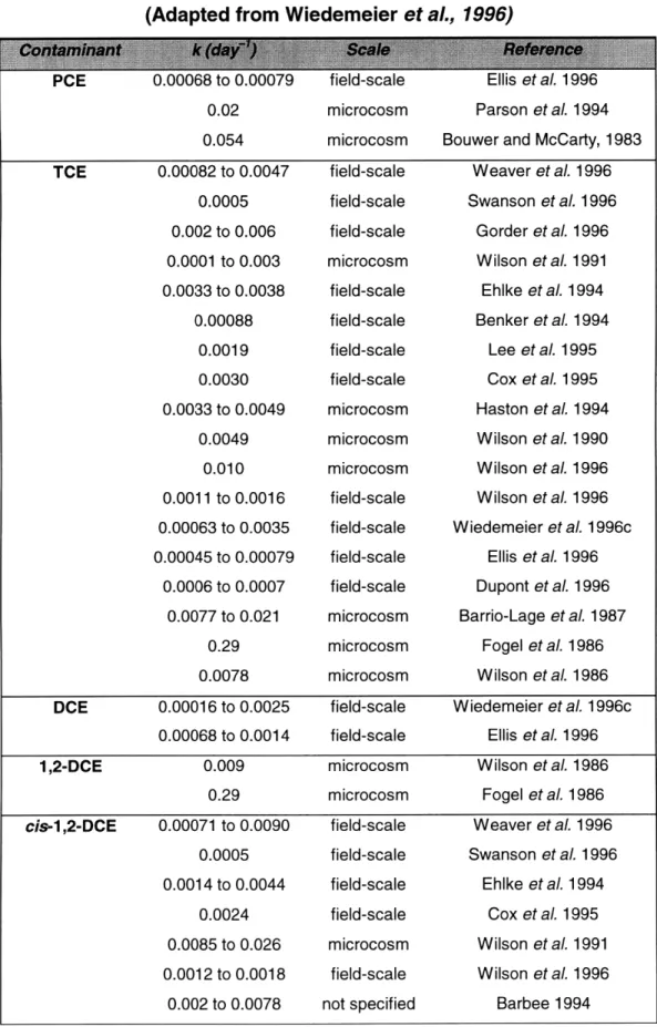
Vmax divided by Km is the effective first-order rate constant k. Some values of k reported in the literature are listed in Table 4.1.
Table 4.1. Biodegradation rate constants. (Adapted from Wiedemeier et al., 1996)
0.02 0.054 0.00082 to 0.0047 0.0005 0.002 to 0.006 0.0001 to 0.003 0.0033 to 0.0038 0.00088 0.0019 0.0030 0.0033 to 0.0049 0.0049 0.010 0.0011 to 0.0016 0.00063 to 0.0035 0.00045 to 0.00079 0.0006 to 0.0007 0.0077 to 0.021 0.29 0.0078 microcosm microcosm field-scale field-scale field-scale microcosm field-scale field-scale field-scale field-scale microcosm microcosm microcosm field-scale field-scale field-scale field-scale microcosm microcosm microcosm Parson et al. 1994 Bouwer and McCarty, 1983
Weaver et aL 1996 Swanson et aL 1996 Gorder et al. 1996 Wilson et al. 1991 Ehlke et al. 1994 Benker et aL 1994 Lee et al. 1995 Cox et al. 1995 Haston et al. 1994 Wilson et aL 1990 Wilson et al. 1996 Wilson et al. 1996 Wiedemeier et aL 1996c Ellis et al. 1996 Dupont et al. 1996 Barrio-Lage et al. 1987 Fogel et al. 1986 Wilson et al. 1986
DCE 0.00016 to 0.0025 field-scale Wiedemeier et al. 1996c
0.00068 to 0.0014 field-scale Ellis et al. 1996
1,2-DCE 0.009 microcosm Wilson et al. 1986
0.29 microcosm Fogel et al. 1986
cis-1,2-DCE 0.00071 to 0.0090 field-scale Weaver et al. 1996 0.0005 field-scale Swanson et al. 1996 0.0014 to 0.0044 field-scale Ehlke et al. 1994
0.0024 field-scale Cox et al. 1995
0.0085 to 0.026 microcosm Wilson et al. 1991 0.0012 to 0.0018 field-scale Wilson et al. 1996
0.002 to 0.0078 not specified Barbee 1994
28
trans-1,2-DCE 0.009 not specified Tabak et aL 1981
0.005 microcosm Wilson et al. 1982
vinyl chloride 0.00041 to 0.0071 field-scale Weaver et al. 1996 0.0085 field-scale Cox et al. 1995 0.00003 microcosm Barrio-Lage et aL 1990
0.00038 to 0.0013 field-scale Wiedemeier et al. 1996c
0.00086 to 0.0010 field-scale Ellis et aL 1996
From the data the trend of decreasing rates with decreasing levels of chlorination is apparent. The step to convert cis-1,2-DCE to vinyl chloride may be considered rate-limiting.
The degradation of these chlorinated compounds, however, is clearly related to residence time and the availability of certain species of bacteria: the longer the compound is exposed to bacterial activity in the sediment, the more opportunity it has for degradation. The question is, how far along the chain can the mechanism get before the plume leaves the sediment? The answer will depend upon the hydrology of the situation and the importance of other attenuation processes, such as sorption. For this purpose, then, a sediment model must be constructed.
5. Sediment Model
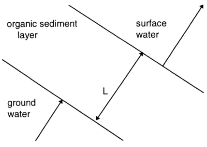
A mass balance of contaminants was taken over a control volume of sediment, as shown below in Figure 5.1. This is a very simple one-dimensional model with
ground-water flow perpendicular to the sediment boundary. Once the
hydrogeology has been characterized, then it will be possible to determine the major contributors to natural attenuation by performing a simple mass balance.
organic sediment layer
surface
water
Figure 5.1. Sediment model control volume.
5.1 Hydrogeological considerations
Flow is perpendicular to the sediment boundary and can be characterized as Darcian. The pond itself is contained in a collapse structure of saturated sand and gravel with porosity (n) estimated at 0.39 by LeBlanc (ABB 1994). Measured values of hydraulic conductivity (K) vary widely, from 10 to more than 300 ft/day (ABB 1994, Walter 1996). The hydraulic gradient (dh/dx) averages 0.002 in the vicinity of the pond (Walter 1996, Jordan 1989). Using Darcy's law,
q = -K dh/dx (2)
v=q/n (3)
= -K dh/dx (4)
n
= 0.05 - 1.5 ft/day
where q is the discharge per unit area into and out of the sediment column (ft/day) and v is the interstitial velocity of the flow (ft/day).
5.2 Mass transport processes
5.2. 1 Advection with sorption
Because a simple retardation model is used to characterize sorption, sorption will be considered together with advection, using a scaled-down value of velocity.
Advection and sorption flux is therefore
Jadv = cV /R (5)
where Jadv is the advective flux, c is the contaminant concentration, and R is the retardation factor used to scale the velocity.
The retardation factor R may in turn be determined from
R = 1 + pbKd/n (6)
Kd = Kocfc (7)
where pb is the bulk density of the matrix, Kd is the distribution coefficient of the contaminant onto the solid phase, Koc is the organic carbon partition coefficient for the contaminant, and foc is the fraction of organic carbon present in the soil. Here the bulk density is approximately 1.8 g/cm3 and the organic carbon soil fraction is approximately 0.001 (ABB 1995). The partition coefficient Koc can be determined from the octanol-water partition coefficient from the empirical relationship
log Koc = 0.544 log Kow + 1.377 (8) (Hemond and Fechner 1994). Residence time tres may then be estimated as
tres = L / (v / R) (9)
where L is the depth of the sediment layer, estimated at 5 feet on average (HAZWRAP 1995a). Values of log Ko, log Koc, R, and tres are tabulated in Table 5.1.
Table 5.1. Retardation coefficients for chlorinated solvent contaminants.
PCE 2.88 2.94 5.0 17 to 50
TCE 2.42 2.69 3.3 11 to 33
cis-1, 2-DCE 1.86 2.39 2.1 7 to 21
vinyl chloride 0.60 1.70 1.2 4 to 12
By comparison, travel time from the sewage treatment plant to the pond has been estimated at 4.2 years (Walter et al. 1996).
5.2.2 Dispersion
Effects due to dispersion are expected to be small relative to the biodegradation and sorptive advection terms.
5.2.3 Volatilization
Volatilization from the sediment column is expected to be negligible, as the system is saturated above and below on all sides, although volatilization of the contaminants from the water column is likely and will be discussed as part of the water column model.
5.2.4 Biodegradation
The strong incidence of DCE, particularly cis-1,2-DCE, in the plumes surrounding Ashumet Pond indirectly indicates the likelihood that biodegradation has already been occurring in the Ashumet Valley plume (ABB 1994). Concentrations of cis-1,2-DCE are higher in areas of high specific conductivity and boron, indicators of the sewage plume region (Eichler 1997). Vinyl chloride, another potential product, has never been detected within the plume or sediment column, however.
Stronger evidence for biodegradation can be found by determining the ratio of 32
cis- to trans-1,2-DCE. Of 32 total DCE detections in the Ashumet Valley
ground-water plume, 31 were of the cis isomer (ABB 1995). Of these detections, the mean concentrations of DCE were 27.4 and 0.3 gg/L of cis and trans, respectively (ABB 1995). Because biodegradation generally produces cis-1,2-DCE rather than trans-1,2-DCE, the large quantity of cis compared to trans is evidence that reductive dechlorination has been taking place in the Ashumet Valley plume. Comparing relative quantities of PCE to cis-1,2-DCE, the trend is
also apparent: the ratios of concentration for PCE to cis-1,2-DCE change from 2.5 near the Ashumet Valley "hot spot" to about 0.32 off the western edge of Ashumet Pond (HAZWRAP 1995a). Mass estimates of PCE, TCE, and cis-1,2-DCE by Eichler, however, do not indicate substantial enough biodegradation to justify natural attenuation as a sole remediation strategy for the ground-water
plume (1997).
For Ashumet Pond sediment, samples taken by Walter et al. were indicated as having a "distinct hydrogen sulfide smell," which would indicate anoxic conditions (1996). Taken together with the organic content and the presence of excess nutrients contributed by the sewage plume, it is reasonable to expect anaerobic biodegradation to take place in the sediment.
Biodegradation flux for each contaminant, Jbio,i, is then the product of the rate constant and the contaminant concentration.
5.2.5 Mass transport results
The basic equation for mass transport is
dc -v dc d dc
= -- + - (D ) - kc (10)
dt R dx dx dx
where D is the dispersion coefficient (ft2/day) and k is the rate constant (day-l).
The ground-water plume is approximately at steady-state, as long as the source (i.e., the sewage treatment plant) remains at steady-state and sufficient time is
available for transport. This would indicate that the contaminant concentrations entering the sediment bed will be at steady-state as well.
Dispersion is likely to be small relative to the advection and biodegradation terms, since the change in the concentration gradient over the length of the sediment column is expected to be negligible. Ignoring dispersion (D is zero),
v dc
vdc = -kc (11)
R dx
which has the solution
c(x)= co exp(-kRx v) (12)
where L is the sediment thickness (ft) and co is the contaminant concentration in the ground-water plume (gg/L). The sediment may be distinguished from the
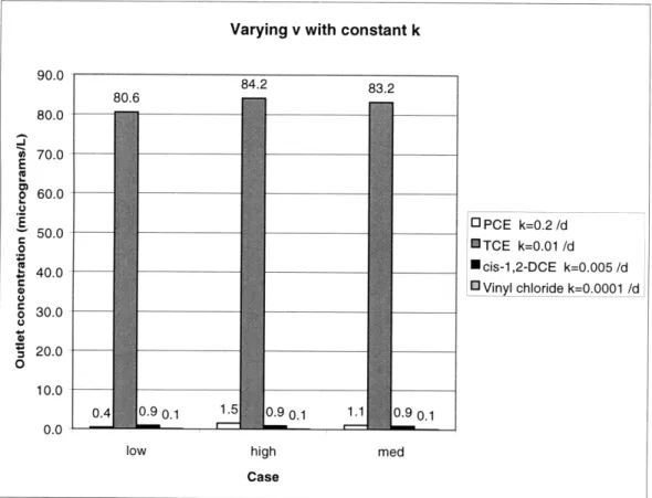
rest of the porous media by its organic content and is on average 5 feet thick (HAZWRAP 1995a). Results calculated over a range of k and v values are included below as Figures 5.2 and 5.3.
From these results, several points become apparent. The first is that PCE and TCE, as expected, have the most potential for biodegradation. Another is that this model has not included a source term, particularly for DCE and vinyl chloride, to show that these contaminants can be produced from the first. Because DCE shows approximately no degradation, it is assumed that, to a first approximation, vinyl chloride is not being produced in any noticeable quantity and that cis-1,2-DCE will be the dominant product, resulting from TCE degradation. Furthermore, microbes that participate in reductive dechlorination generally convert PCE and TCE to cis- rather than trans-1,2-DCE, so that the cis isomer would likely be the favored product. In the event that all of the TCE converted becomes cis-1,2-DCE, final concentrations of cis-1,2-DCE might
Varying k with constant v=1 ft/d 100.0 90.0 05.9 83.2 80.0 E E 70.0 .1 60.0 oPCE c nTCE .2 50.0 U cis-1,2-DCE S40.0 ]a Vinyl chloride S33.4 o0 . 30.0 O 20.0 10.0
100
0.9 0.1
0.9 0.1
1.1
0.9 0.1
0.0low high med
Case
Varying v with constant k 90.0 884.2 83.2 80.6 80.0 *A 70.0 E 2 60.0 E 13 PCE k=0.2/d 50.0 50.0 TCE k=0.01 /d , 40.0 cis-1,2-DCE k=0.005/d Vinyl chloride k=0.0001 /d 30.0 20.0 0 10.0 0.4 0.9 0.1 1.5 0.9 0.1 1.1 0.9 0.1 0.0
low high med
Case
Figure 5.3. Sediment model results over a range of v with constant k.*
* Initial concentration values from HAZWRAP (1995a)
6. Water Column Model
The water column model involves mechanisms similar to those of the sediment model. Because the pond is stratified during the summer months, the analysis may be conducted in two parts to consider stratified and well-mixed conditions. The well-mixed water column can be modeled as a Continuous Stirred Tank Reactor (CSTR) with one inlet, the ground-water plume; and two outlets, exchange with the atmosphere and discharge downgradient from the pond. Adsorption onto particles is considered negligible, given the expected low bulk contaminant concentration. When the pond is stratified, ground-water recharge to the pond will primarily remain within the layer or layers in which it enters. If the plume enters the epilimnion, volatilization will be the dominant process by which dissolved solvents will exit the pond. If the plume enters the hypolimnion, the
contaminants will most likely leave via pond discharge back into the ground-water system, breaking down further on the way back through the sediment bed and in the soil matrix.
6.1 Well-Mixed Model
The contaminant mass balance for the well-mixed pond is
Fwo - Fv - cw,Qo, = 0 (13)
for steady-state conditions, where Fwo is the inlet contaminant loading ( pg/day),
Fv is the volatilization rate by mass (gg/day), cw is the homogeneous
concentration of the contaminant in the pond (gg/m3), and Qout is the volumetric flow rate from the pond to ground-water discharge (m3/day).
Inlet contaminant loading Fwo may be expressed in terms of the inlet concentration, cwo(g/m3) and flow rate Qin (m3/day) as
Fwo = cwoQin (14)
The volatilization rate by mass FA may be expressed as a product of the volatilization flux Jv (gg/m2/day) and the area of the pond surface A (m2). Using the thin film model of air-water exchange, which assumes that molecular diffusion across a stagnant film of water is the rate-limiting step for volatilization,
,= -
c
-
CAR
(15)
where Dw is the molecular diffusion coefficient for the contaminant in water (ft2/day),
&S
is the thickness of the hypothetical film of water (ft), Cai, is the contaminant concentration in the air (gg/dm3), and H is the dimensionless Henry's Law constant.If the concentration of the contaminant in the air is assumed to be zero, the 37
volatilization flux may be expressed in terms of a water-side piston velocity k, (ft/day) that is dependent on the physical properties of the contaminant:
Jv -- = -kvc W (16)
The piston velocity for a contaminant may be expressed to a good approximation in terms of the piston velocity of a tracer chemical in water and the molecular weights of the contaminant and of the tracer:
k = k -Vt MWracertrace, (17)
kV ktracer MWcontaunant (17)
A typical choice for a tracer on the water side is oxygen. The liquid-phase mass transfer coefficient for a pond or lake is largely dependent upon wind speed. The wind speed on Cape Cod and in the vicinity of the pond is 9 mph from July to September and about 12 mph from October to March (ABB 1995). Using an average wind speed of 10 mph (4.5 m/s) and assuming this speed is measured at a height of 5 cm above the pond surface, ktrace, is approximately 7.9 ft/day, as estimated from Figure 6.1 (Thibodeaux 1979).
Wind velocity at 10 m above surface (calculated m/s)
0 5 10 15 20 25 30
2 4 6 8 10 12
Wind velocity at 5 cm. above surface (m/s)
Figure 6.1. Change in liquid-phase mass transfer coefficient for oxygen with wind velocity. (Adapted from Thibodeaux, 1979)
Values of piston velocity below in Table 6.1.
for PCE, TCE, cis-1,2-DCE, and vinyl chloride are listed
Table 6.1. Water-Side Piston Velocities for Aqueous Chlorinated Solvents.
PCE 165.83 3.5
TCE 131.39 3.9
1,2-DCE 96.94 4.5
Vinyl chloride 62.50 5.7
Then the homogeneous pond concentration may be expressed as
c = cwoQ0 (18)
Skv A + Qout
Ashumet Pond has an area of 8.8 million square feet (HAZWRAP 1995a); recharge from and discharge to ground water are both estimated at 300,000 ft3
/day (ABB 1995). Inflow from the Ashumet Valley plume is estimated from 15,200 to 37,300 ft3/day (Walter et al. 1996). Assuming an inflow of 25,000 ft3/day, bulk contaminant concentrations in the pond can be calculated; these are listed in Table 6.2, using the assumption that all of the converted PCE from the sediment column is TCE and all the converted TCE is cis-1,2-DCE, based on median values calculated in Section 5.2.5.
Table 6.2. Bulk contaminant concentrations for the well-mixed case.
PCE 11 5
TCE 765 5
cis-1,2-DCE 28 70
Vinyl chloride 0.59 2
6.2 Stratified Pond Model
Ashumet Pond is stratified during the summer months, with the thermocline estimated from 9 to 11 m below the pond surface in the late summer (HAZWRAP 1995b). This graph is included as Figure 6.2. From three-dimensional plots of the Ashumet Valley solvent plume in relation to the pond, included as Figure 6.3, it appears that the plume primarily discharges to the upper third of the pond, or the epilimnion (ABB 1995). In this case the epilimnion may be considered well-mixed, and although some molecular diffusion would
occur across the metalimnion, the chief source of attenuation of the solvents would be through volatilization.
A December t993 I
!'
B April 1B94 2 10 is 12 2D ' 2.---0 2 4 6 0 10 '12 ;A n 2 4 6 R 10 12 D september 1994 C June 1994u _LEG IL. 1.fO Di.wl-cd Ox .,,ni (juWL)
( 1 1.1 ti 11; h. r ( i::
Figure 6.2. Stratification of Ashumet Pond.
41 C -2 4 6 42C ,3-] I I i __~__1 1~_:_11_1_____I~-_~=~-= W. l ,, ... ww!amm 114: CU35 FI Er AFF -A'134L2 ,CDH
Figure 6.3. Three-dimensional view of Ashumet Valley VOC plume. (ABB 1995)
The steady-state contaminant mass balance would then be
cwoin - kvAc, = 0 (19)
where the first term corresponds to contaminant loading from the ground-water plume and the second term corresponds to volatilization, using the thin film model as in Section 6.1.
Solving for the bulk concentration of contaminant in the epilimnion, CA, gives
cw = Ck
Q
k A (20)
Estimated values of bulk contaminant concentration in the pond epilimnion are given in Table 6.3.
Table 6.3. Bulk contaminant concentrations for the stratified case.
7. Discussion and Recommendations
7.1 Sediment Model Results
As expected, anaerobic biodegradation of dissolved PCE and TCE has been and continues to progress throughout the Ashumet Valley ground-water plume and in the Ashumet Pond sediment. Most, if not all, of the product is likely to be cis-1,2-DCE, depending on the type of bacteria present in the microbial population.
Although biodegradation is the dominant attenuation process in the sediment, the sorption may also be a contributing factor, particularly for PCE and TCE. Transport is primarily through advection. Although these dissolved halogenated aliphatic compounds are likely to be transported into the water column, they have not yet been detected in the surface water, possibly due to their high volatility and large dilution effects.
7.2 Water Column Model Results
As expected, the predicted bulk contaminant concentration in the water column is very low, much lower than expected detection levels (1 gg/L detection limit on each contaminant) or maximum contaminant levels, due to large dilution and volatilization. Although the model did not take into account seasonal variations in volatilization due to temperature, the concentrations involved are so low that this factor is not likely to be significant. Results were similar for both the well-mixed and stratified cases, as volatilization seemed to be the largest contributor to attenuation in the water column.
7.3 Possibilities for Future Investigation
Enhancement of anaerobic biodegradation, since it mostly produces DCE, would not be likely to do very much good. Because DCE may be aerobically mineralized, it may be possible to encourage its aerobic breakdown, perhaps by means of some sort of soil aeration system; but for this system, since TCE is so prevalent and is somewhat resistant to this type of degradation, this may not be recommended. The best possible options would probably involve simply removing the chlorinated contaminants rather than relying on bioremediating them, at least until bacterial strains that are capable of mineralizing these contaminants become commercially available.
One possible project that may be useful for a more thorough understanding of this process might be to conduct microcosm studies, as described in Section 4.3, using Ashumet Pond sediment. Some procedural guidelines can be found in
8. References
ABB Environmental Services, Inc., 1994. Southeast Region Groundwater Operable Unit Remedial Investigation Report (Including Region III). (Draft) Volume II. Oak Ridge, TN: Hazardous Waste Remedial Actions Program (HAZWRAP), August 1994.
, 1995. Ashumet Valley Groundwater Operable Unit Remedial
Investigation Report. (Draft) Volumes I-I111. Portland, Maine: Hazardous Waste Remedial Actions Program (HAZWRAP), April 1995.
Anid, P. J.; Ravest-Webster, B. P.; and T. M. Vogel, 1993. Effect of Hydrogen Peroxide on the Biodegradation of PCBs in Anaerobically Dechlorinated
River Sediments. Biodegradation. 4: pp. 241-248.
Barrio-Lage, G.; Parsons, F. Z.; and R. S. Nassar, 1987. Kinetics of the Depletion of Trichloroethene. Environmental Science & Technology. 21: pp. 366-370.
Barrio-Lage, G.; Parsons, F. Z.; Nassar, R. S.; and P. A. Lorenzo, 1986.
Sequential Dehalogenation of Chlorinated Ethenes. Environmental
Science & Technology. 20: pp. 96-99.
Bouwer, E. J. and P. L. McCarty, 1983. Transformations of 1- and 2-Carbon
Halogenated Aliphatic Organic Compounds Under Methanogenic
Conditions. Applied and Environmental Microbiology. 45: pp. 1286-1294.
deBruin, W. P.; Kotterman, M. J. J.; Posthumus, M. A.; Schraa, G.; and A. J. B.
Zehnder, 1992. Complete Biological Reductive Transformation of
Tetrachloroethene to Ethane. Applied and Environmental Microbiology. 58: pp. 1996-2000.
DiStefano, T. D.; Gossett, J. M.; and S. H. Zinder, 1992. Hydrogen as an 46
Electron Donor for Dechlorination of Tetrachloroethene by an Anaerobic Mixed Culture. Applied and Environmental Microbiology. 58: pp. 3622-3629.
E. C. Jordan, 1989. Hydrogeologic Summary, Task 1-8, Status: April 1989. (Draft) Oak Ridge: HAZWRAP Support Contractor Office, April 1989.
Eichler, H.J., 1997. Natural Attenuation of Chlorinated Solvents at Ashumet
Valley, Cape Cod, Massachusetts. Master of Engineering Thesis in Civil
and Environmental Engineering. Massachusetts Institute of Technology, 1997.
Ellis, Lynda, 1997. Tetrachloroethene Pathway Map (Anaerobic). University of Minnesota. <http://dragon.labmed.umn.edu/-lynda/tce2/tce2_map.html>,
1 Aug. 1997.
Fathepure, B. Z. and S. A. Boyd, 1988. Dependence of Tetrachloroethylene
Dechlorination on Methanogenic Substrate Consumption by
Methanosarcina sp. Strain DCM. Applied and Environmental
Microbiology. 54: pp. 2976-2980.
Fathepure, B. Z.; Nengu, J. P.; and S. A. Boyd, 1987. Anaerobic Bacteria That Dechlorinate Perchloroethene. Applied and Environmental Microbiology. 53: pp. 2671-2674.
Freedman, D. L., and J. M. Gossett, 1989. Biological Reductive Dechlorination
of Tetrachloroethylene and Trichloroethylene to Ethylene Under
Methanogenic Conditions. Applied and Environmental Microbiology. 55: pp. 2144-2151.
Hazardous Waste Remedial Actions Program, 1988. Ashumet Pond Trophic State and Eutrophication Control Assessment, Final Report: Task 1-4. Oak Ridge: Hazardous Waste Remedial Actions Program (HAZWRAP), March 1988.
, 1995a. "Ashumet and Johns Ponds 1993 Annual Report." Vol. I and II. Oak Ridge: Hazardous Waste Remedial Actions Program (HAZWRAP), June 1995.
, 1995b. "Ashumet and Johns Ponds 1994 Annual Report." (Draft) Vol. I
and II. Oak Ridge: Hazardous Waste Remedial Actions Program
(HAZWRAP), June 1995.
Hemond, H.F. and E. Fechner, 1994. Chemical Fate and Transport in the Environment. Academic Press, San Diego.
Jacobs Engineering Group, Inc., 1997. Ecological Studies: 1997 Annual Report for FS-12, SD-5, and CS-10 Groundwater Plumes. (Draft) MMR Plume Response Program. December 1997.
Johnston, J. J.; Borden, R. C.; and M.A. Barlaz, 1996. Anaerobic Biodegradation of Alkyl Benzenes and Trichloroethylene in Aquifer Sediment Down Gradient of a Sanitary Landfill. Journal of Contaminant Hydrology. 23: 263-283.
McCarty, P.L., 1997. Breathing with Chlorinated Solvents. Science. 276: pp. 1521.
Massachusetts Military Reservation. Massachusetts Military Reservation.
<http://www.mmr.org/>.
Maymb-Gatell, X.; Chien, Y.; Gossett, J.M.; and S.H. Zinder, 1997. Isolation of a Bacterium That Reductively Dechlorinates Tetrachloroethene to Ethene.
Science. 276: pp. 1568-1571.
Palmer, Christopher M., 1996. Principles of Contaminant Hydrogeology. CRC Lewis Publishers, Boca Raton, Fla.
Rodricks, J.V., 1992. Calculated Risks: Understanding the toxicity and human
health risks of chemicals in our environment. Cambridge University Press,
New York.
Schwarzenbach, R.P.; Gschwend, P.M.; and D.M. Imboden, 1993.
Environmental Organic Chemistry. J. Wiley, New York.
Schwille, F., 1988. Dense Chlorinated Solvents in Porous and Fractured Media.
Lewis Publishers, Chelsea, MI.
Swindoll, C. M., and M. A. Troy, 1996. Demonstrating Intrinsic Bioremediation Potential of Chlorinated Aliphatic Hydrocarbons. In The Proceedings of
the 1996 Petroleum Hydrocarbons & Organic Chemicals in Groundwater: Prevention, Detection, and Remediation Conference. Houston: Nov.
13-15, 1996. pp. 383-398.
Thibodeaux, L.J., 1979. Chemodynamics. John Wiley & Sons, New York.
Vogel, T. M.; Criddle, C. S.; and P. L. McCarty, 1987. Transformations of
Halogenated Aliphatic Compounds. Environmental Science &
Technology. 21: pp. 722-736.
Vogel, T. M., and P. L. McCarty, 1985. Biotransformation of Tetrachloroethylene to Trichloroethylene, Dichloroethylene, Vinyl Chloride, and Carbon Dioxide
Under Methanogenic Conditions. Applied and Environmental
Microbiology. 49: pp. 1080-1083.
Walter, D. A. and D. R. LeBlanc, 1997. Geochemical and Hydrologic Considerations in Remediating Phosphorus-Contaminated Ground Water in a Sewage Plume Near Ashumet Pond, Cape Cod, Massachusetts. U. S. Geological Survey Open-File Report 97-202. USGPO, Washington.
Walter, D. A.; Rea, B. A.; Stollenwerk, K. G.; and J. Savoie, 1996. Geochemical and Hydrologic Controls on Phosphorus Transport in a Sewage-Contaminated Sand and Gravel Aquifer Near Ashumet Pond, Cape Cod, Massachusetts. U. S. Geological Survey Water-Supply Paper 2463.
USGPO, Washington.
Wetzel, 1972. Limnology. Saunders, Philadelphia.
Wiedemeier, T. H.; Wilson, J. T.; Miller, R. N.; and D. H. Kampbell. United States Air Force Guidelines for Successfully Supporting Intrinsic Remediation with an Example from Hill Air Force Base.
Wiedemeier, T. H., M.A. Swanson, D.E. Moutoux, E.K. Gordon, J.T. Wilson, B.H. Wilson, D.H. Kampbell, J.E. Hansen, P. Hass, and F.H. Chapelle, 1996. Technical Protocol for Evaluating Natural Attenuation of Chlorinated
Solvents in Groundwater. San Antonio: Air Force Center for
Environmental Excellence, Technology Transfer Division, Brooks Air Force Base, November 1996.