A bio-inspired approach to increase device-level energy
density
by Alan Ransil
B. S. Stanford University, 2010
S.M. Massachusetts Institute of Technology, 2013
Submitted to the Department of Materials Science and Engineering on April 13, 2018, in partial fulfillment of the
requirements for the degree of
Doctor of Philosophy in Materials Science and Engineering at the
MASSACHUSETTS INSTITUTE OF TECHNOLOGY June 2018
Massachusetts Institute of Technology 2018. All rights reserved.
Author...Signature
redacted...
Department of Materials Science and Engineering April 13, 2018
Signature redacted
C ertified by ... ...
Prof. Angela M. Belcher Professor of Biological Engineering and of Materials Science and Engineering
Signature redacted
Thesis SupervisorA ccepted by ... ...
Prof. Donald R. Sadoway Chairman, De p mental Committee on Graduate Studies
MASSACJIUET OFT FNSITUTE
JUN 11 2018
LIBRARIES
MITLibraries
77 Massachusetts Avenue
Cambridge, MA 02139 http://ibraries.mit.edu/ask
DISCLAIMER NOTICE
Due to the condition of the original material, there are unavoidable
flaws in this reproduction. We have made every effort possible to
provide you with the best copy available.
Thank you.
Some pages in the original document contain text
that is illegible.
A bio-inspired approach to increase device-level energy
density
by Alan Ransil
Submitted to the Department of Materials Science and Engineering on April 13, 2018 in partial fulfillment of the requirements for the degree of Doctor of Philosophy in Materials
Science and Engineering
Abstract
Battery research has historically focused on improving the properties of the active materials that directly store energy. This research has resulted in active materials with higher spe-cific capacity, increased the voltage of batteries in order to store more energy per electron, and lead to the development of electrolytes and binders compatible with high-performance active materials. However, Lithium-Ion Batteries (LIB) are nearing the limits of energy density achievable using a traditional battery design. Structural batteries are a fundamen-tally distinct route to optimize device performance, aiming to replace structural materials such as metals, plastics, and composites with multifunctional energy-storing materials. By increasing the device mass fraction that is devoted to energy storage, this strategy could more than double the battery life of electronic devices without requiring improved active materials. In this thesis, I show that rigid, load-bearing electrodes suitable for structural batteries can be fabricated using a novel silicate binder. This binder .can be used to dis-tribute load both within layers and throughout the battery by adhering adjacent battery layers. This innovation turns the entire battery stack into a novel monolithic engineering ceramic referred to as a Structural Ceramic Battery (SCB). Unlike previously published binders, this material does not soften with the introduction of electrolyte, it promotes charge transport within the electrode, and it is compatible with a range of active materi-als employed in batteries today. This thesis furthermore outlines versatile manufacturing methods making it possible to produce SCBs with a wide variety of shapes and form fac-tors amenable to large-scale production. It is envisioned that this SCB architecture will be
used to improve the energy density of both ground-based and flying electric vehicles, and that as improved active material chemistries are discovered they will be dropped in to this architecture in order to promote future increases in vehicle-level energy density.
Thesis Supervisor: Angela M Belcher
Acknowledgements
"I may be wrong and you may be right,
and by an effort, we may get nearer to the truth."
-Karl Popper, The Open Society and its Enemies, 1945
I showed up in Angie's office in 2012 wanting to work on new battery architectures, and she was willing to spend years mentoring me and helping me grow as an engineer. Angie's research group is a unique place where it feels like anything is possible. Her ability and desire to foster a culture of unbounded creativity allow us all to envision and work towards genuinely new solutions to consequential problems. Working as a graduate student in her lab has been an immense privilege, and want to thank her for tremendous insight and mentorship over the course of my degree.
Professors Yang Shao-Horn and Niels Holten-Andersen have likewise helped me a huge amount during my PhD. Their perspectives on solving electrochemical and mechanical problems have repeatedly given me unexpected ideas, challenged me to solve problems in new ways, and shown me flaws in my thinking to help me strengthen my work.
I'm grateful to the whole Belcher group for helping me with tasks as mundane as finding the alconox to ones as esoteric as applying Popperian epistemology to puzzling experimental results. Throughout my PhD Jackie has worked alongside me, sharing her genius solutions to phage-based problems I was struggling with that she had already solved. Dahyun (now Professor Oh) taught me how to amplify phage, how to make biotemplated battery materials, designed many of the protocols I used during my PhD, and would help me better understand what my batteries were doing. Maryam would always give me insight about my results and what to try next. Geran has frequently helped me troubleshoot problems I was having in lab. Nimrod would help me brainstorm new ideas and come up with solutions to experimental issues. It is amazing how much Jifa knows about getting experiments to work, and he would always help me with my synthesis woes. Shuya has a wealth of electrochemical knowledge, and has helped me improve my experimental setup immensely. Uyanga has come up with brilliant solutions to short phage problems. Briana likewise invented new phage constructs that made progress in our DARPA program possible. Nir would help me work through why my batteries were behaving the way they were and figure out what to do to fix them Thank-you to Griffin for being our group's safety EHS representative; you make it look easy but I'm sure it's not. Col. Burpo came up with the protocol for biotemplated nanofoams that I spent much of my time working on and alerted
me to the tremendous gains that structural batteries could make possible. Ngozie has an amazing knack for knowing what avenue of research to explore (even when I doubted it -I'm still amazed about the phosphides). And thank you to Peter Jansen for keeping me from taking myself too seriously.
The undergraduates I've worked with have not only helped me get science done faster but given their own insights that have helped shape my work. Thank you to Saleem, Fauziah, Akshay, Sam and Isaiah.
Thank you to Dr. Yun who helped me with TEM, Scott Speakman and Charlie Settens of the CMSE XRD lab, Patrick Bosivert and Bill DeNatale who have helped immensely with SEM, Thibaut Divoux who performed scratch tests, Alan Schwartzman who performed nanoindentation tests, and Laurent Lacordier and Ganesh Sundaram from Cambridge Nan-otech.
A great number
of
people have helped me better contextualize materials research in terms of its impact, and better understand how to bring materials out of the lab. Thank you to Changqiong Zhu, Rupak Chakraborty and Wenhao Sun for working with me to bring materials into the 'real world.' Kieran Strobel has shown me how to solve problems in Aerospace and I hope to continue working with him to realize the potential of SCBs. Stephen Steiner has shown me how much you can do with a deep determination to bring materials to market. Mark Edwards has supported both me and Stevie immensely. Francis O'Sullivan has continually helped me to better understand the economics of energy markets, what problems are important to solve, and why. Carlos Solares has mentored me in the business of making materials. Also thank you to Karen, Leon, Amy and Cory at the Deshpande center for not just funding part of my research but supporting us as we move towards a structural battery that can enable new vehicle designs.Many of my former mentors taught me lessons that were often remembered during my PhD. Among these are Yet-Ming Chiang, Billy Woodford, Michael McGehee, Richard
Cushman, Carol Stanton, Jack Coakley and Diane Munroe.
It would feel strange not to mention some of the people who have had a huge intellectual effect on me, but who I've never met and won't appear in the citations below. In this category I'd like to acknowledge Karl Popper, Steve Grand, David Deutsch, Naomi Oreskes, Dan Ariely, James Baldwin, Philip Pullman, Thomas Piketty, Vannevar Bush, Robert Reich, Arlie Russell Hochschild, Timothy Snyder, and Eddie Izzard.
I grew up in an environment that felt a lot like Angie's lab, in that creativity was encouraged and I was able to learn and build anything as long as I cleaned it up afterwards. As a result, I was able to study chemistry (burning things, water electrolysis, acid and base reactions, crystal growth), physics (building motors from scratch, a bed of nails, Ruben's tube, the magic of siphons), biology (lizards, frogs, earthworms, dissecting squid, gardening), filmmaking, and history (historically themed dinner parties) throughout my childhood. Thank you Mom, especially for the time you homeschooled me. Thank you Dad for never answering questions with "because." Thank you Bryan for putting up with me and being my partner in crime.
Finally, I want to thank Chelsea. We got engaged six months after I started in the Belcher group, and were married in 2014. It's striking how many of the things we dreamed of then, like getting a dog together, are real parts of our life now. I of course want to thank Chelsea for supporting, being there for, and helping me on the winding and difficult road that is graduate school. What I want to thank her more for is having faith in me throughout. And most of all, I want to thank Chelsea for sharing her life with me, pushing me to be better, and valuing growth over validation. I am so lucky to have found you.
Contents
1 Introduction: the case for structural energy storage
1.1 Miltiftinctional materials in nature . . . .
1.1.1 Where should we expect to find multifunctional materials? . . . . . 1.1.2 When should we employ multifunctional materials? . . . . 1.2 The limits of electrochemical energy storage for vehicles . . . . 1.3 Structural batteries in ground vehicles . . . . 1.4 Structural batteries in airborne vehicles . . . .
2 Strategies for structural energy storage
2.1 Transferring loa(i to conventional batteries . . . . . 2.2 Transferrinig load to current collectors . . . . 2.3 Carbon fiber electroles . . . . . 2.4 Structural polymer-ba set binders . . . .. 2.5 Freestanding electrodes . . . . 2.6 Structural ceranie batteries (SC1Bs): a new design
3 Methods 3.1 Nanoindentation .. . . ... . . . .. . . . . .. . . . . 3.2 Electrode fabrication .. ... . .. . . . .. . . . . 14 14 16 21 23 26 28 32 . . . . 32 35 . . . . 37 . . . . 41 . . . . 44 . . . . 48 50 50 51
3.3 3.4 3.5 3.6 3.7 3.8 3.9
Fracture toughness ieasuremnwts . . . .
Rate capabilitv and cycle life measurements
Transmission electron microscopy . . . .
X-Ray Diffraction . . . .
Scanning electron microscopy . . . .
Electrociemical impedance spect roscopy
Tensile Tests . . . .
4 Evaluating the properties of inorganic polymer binders 4.1 Alkali silicates . . . .
4.1.1 Alkali silicate properties and synthesis . . . . 4.1.2 Uses of alkali silicates in industry . . . . 4.2 Geopolymer binders . . . ..
4.2.1 Uses of geopolymer binders in research an(d in(ustry 4.3 The mechanical properties of silicate binders . . . . 4.3.1 Young's Modulus Comparison . . . . 4.3.2 Fracture toughness measurements . . . .
5 Development of silicate-based electrodes
5.1 Previous use of silica as electrode binders . . . . 5.2 Silicate electrode processing and rate capability . . . . 5.2.1 Silicate electrode composition and processing . . . .
52 . . . . 54 . . . . 55 5 . . . . 56 . . . . .6 57 58 615 69 70 74 74 76 81 . . .. ..81 . . . . 83 . . . . 83
52.2 Comparison to conlventioiial electrodes . . . . . 89
5.3 Silicate-based electrode structure . . . . . 90
5.4 Compatibility of silicate with electrode materials . . . . . 94
6 Fabrication of Structural Ceramic Batteries 98 6.1 Addition of a. temporary binder to electrodes . . . . 98
6.2 Reinforcing SCB electrodes . . . ..101
6.3 Separator development . . . 105
6.4 SCB fabrication . . . 109
7 Mechanical properties of structural ceramic batteries 114 8 Conclusions and Future Outlook 117 8.1 Adjusting binder cheiistry to optimize rate . . . 117
8.2 Optimize mechanical properties . . . 118
8.3 Demonstrate large-scale packaged cells . . . 119
List of Figures
1 Examples of multifunctional materials in living systems . . . . .
1-2 Schematic of an evolutionary design procedure . . . . [7
3 Schematic of a rational design procedure . . . . 18
4 Progression reduction of the energy density of components in a Tesla Model S 27 5 Electric car mass breakdown . . . . 28
6 Effect of structural batteries on UAV endurance . . . . 31
7 Strategies for using conventional batteries as structural elements . . . . 33
8 A design for transferring external load to the current collectors of a battery 36 9 Evaluation of carbon fiber used as a negative electrode in LIBs . . . . 39
10 Synthesis and evaluation of bicontinuous epoxy-ionic liquid electrolytes . . . 42
11 A polymer-based structural battery . . . . 43
12 Freestanding electrode architectures . . . . 46
13 Battery architectures based on fiber morphologies . . . . 47
14 The Structural Ceramic Battery (SCB) architecture . . . . 49
15 The Na20:Sio2 phase diagram . . . . 59
16 Processing of waterglass dried from solution . . . . ... . . . . 60
17 Evaluation of lithitun silicates as ionically conducting materials . . . . 18 Use of lithium silicates as solid electrolytes . . . . 64
21 22 23 24 25 26 27 28 29 30 31 32 33 34 35 36 37 38 39 70 72) 73 79 82 85
Geopolymer setting and structur . . . . . Geopolviners in industry . . . .
Geopolymers composites reinforced with carbon . . . .
Stiffness of silicate binders . . . .
Fatbrication of silicate-based slurry electrodes . . . .
Fracture toughness test results . . . ..
Ceramic Carbon Intercalation Electrodes . . . .
Effect of heat treatment on electrodes . . . .
Ragone plot showing the effect of heat treatment temperature on r
s-LFP electrodes . . . .
Rate curves showing effect of silicate content . . . .
Silicate content strongly affects rate while Super P does not . . . . .
Electrochemical performance comparison to conventional electrodes
TEM investigation of LFP surface . . . .
Elemental mapping of s-LFP electrodes . . . . Elemental mapping of SCB electrode . . . .
XRD analysis of silicate compatibility with LFP . . . .
Long-term cycling stability of silicate-based electrodes . . . .
Polymer reinforcement of thick electrode
fihns
. . . . Inorganic and organic binder structure, effect of plasticizer . . . .Electrode morphology with carbon nanohiber . . . . ate for 86 87 . . . . 88 89 . . . .
91
. .92
. . . . 93 .... 95 . . . . 97 .100 . . . . 101 .103-U
40 Electrochemical performance of electrodes derived fron flexible sheets . . . 104
41 Effect of separator composition on morphology . . . 107
42 Effect of separator composition on transport . . . 108
43 A large-format SCB on a rigid substrate . . . 110
44 Conformal SCB fabrication process . . . 112
45 Full SCB in coin casing . . . 113
46 ASTM E8 sample plan . . . 114
List of Tables
1 Standard reduction potentials of candidate working ions . . . . ... . . . 24
2 Typical electrode composition . . . .
51
3 Composition of portland cement . . . . 66
4 Range of compositions tested for SCBs . . . . 5 Compositions of s-LFP and s-Graphite electrodes used for heat treatment tests . . . .
84
6 Ratio of sodium to silicon measured from TEM EDX . . . . 94
7 Linear carbon-based reinforcement dimensions . . . 102
8 Composition of separator paste . . . ... . . . 106
9 Composition of full SCB on glass slides . . . ..II 10 Composition of full SCB in coin cell . . . 113
1.
Introduction: the case for structural energy storage
The dominant design paradigm in most engineering is to use modular components. These
can be optimized for a single use, can be easily repaired or modified without requiring an
overhaul of the entire design, and because of the restricted interactions between modular
components they lead to devices which fail non-chaotically. By contrast, in the natural
world we frequently find that living systems are composed of multifunctional components.
In this section, I will discuss multifunctional materials in the context of natural systems,
suggest why we find them in natural compared to rationally designed systems, and outline
where we might profitably expect multifunctional materials to improve the properties of
devices. I will then discuss the benefits of applying a structural energy storage paradigm
specifically to cars and aerial vehicles.
1.1. Multifunctional materials in nature
Multifunctional materials are those which are not designed to fulfill only one role, but have
multiple distinct roles in the system to which they belong. These materials are extremely
common in the natural world, in which many of the materials that make up living systems
play multiple distinct roles. Figure 1 gives several examples. One notable design parameter
is that energy storage tends to be highly distributed in living systems, with carbohydrates
being found throughout their tissues. Structural materials frequently fulfill multiple roles,
and immune cells in the case of bone. In addition, many of the tissues which fulfill distinct
roles such as thermally insulating blubber and actuating muscle can be broken down in
order to provide energy. To highlight how alien this concept is in the context of rationally
designed materials, such a design choice might be akin to a car engine burning itself in
order to keep going once it runs out of gas. The engine wouldn't suddenly break down
once this begins, but would simply shrink and become less powerful until either there is no
engine left or until you reverse the process by refueling.
(C) AL (d)
Figure 1: Examples of multifunctional materials in living systems. (a) wood provides structure to trees, as well as storing and distributing sap and nutrients. (b) Marine mammal blubber functions as both energy storage and thermal insulation. (c) muscles serve as actuators, distributed short term energy storage, and can act as long term energy storage which may converted via catabolism. (d) bones are multifunctional materials that both provide structure and produce blood cells.
It should also be mentioned that these multifunctional biological materials frequently
achieve their functionality due to a complex multiscale composite architecture. Wood and
bone, for example, are cellular materials with cells containing sap and marrow respectively
fatty tissue are necessary for their growth and their conversion into fuel for the rest of
the body. Multifunctionality is also built in at many length scales: muscle fibers have
their own complex protein structure and the chemical composition of fat and muscle is
the basis for their their ability to store energy. Similarly, complex multiscale architectures
will be important in the rational design of multifunctional materials and their chemical
composition will be pivotal.
1.1.1. Where should we expect to find multifunctional materials?
Why are rationally designed structures frequently composed of modular, single-function components and when should we expect a design process to result in multifunctional
ar-chitectures a priori? Under what circumstances should we employ multifunctionality in
our designs? This subsection and the following subsection will hazard answers to these
questions.
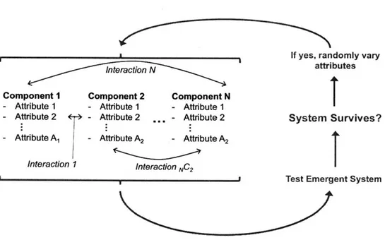
Figure 2 is a schematic of an evolutionary process to design a system. In this schematic,
the behavior of the whole system (in blue brackets) emerges from the attributes of
individ-ual components and the interactions these components. According to this design strategy,
attributes of the system are varied randomly and choice is made based on the emergent
behavior of the entire system. During each design cycle (which may be, for example, the
life cycle of an organism or one round of bio-panning in phage display), the system receives
either a passing grade or a failing grade from the environment. If the system survived, its
I
',. Inte~raction N
Component I Component 2 Component N - Attribute 1 - Attribute 1 - Attribute I
- Attribute 2 - Attribute 2 ,, - Attribute 2 - Attribute A1 -Attribute A2 -Attribute A2
Interaction I Interaction NC 2
If yes, randomly vary
attributes
System Survives?
I
Test Emergent System
Figure 2: Evolutionary design of an organism, where the organism itself is enclosed in blue brackets. While the organism may be composed of many components and these components may each have a large number of relevant attributes, the evolutionary test is done on the emergent system level. We should thus expect multifunctionality rather than modularity.
Because the testing in this paradigm is done on the level of emergent system behavior, we should expect groups of components and their attributes to contribute to a functioning system. We should not necessarily expect the components to have well-defined individual roles. This is of course observed in biology outside of biomaterials. Individual genes, for example, frequently exhibit pleiotropic effects. This means that their mutations affect many attributes of an organism rather than one single attribute.
Rational design processes also test devices at the emergent system level, but they
exhibit another design stage as shown in figure 3. Here is shown a design paradigm in
which the "field test" or physical experiment is analogous to an evolutionary test. This is
a test done of the actual system in the real world. But the system is also tested during
the design process in the head (and frequently in the computer) of whoever is designing it.
This 'Thought Experiment' process, shown in green, represents that design stage.
Rationally Vary
Component I Component 2 Component N Attributes - Attribute I - Attribute 1 - Attribute 1
- Attribute 2 +r4 - Attribute 2 - Attribute 2
- Attribute A, - Attribute A2 - Attribute A2 Inta.m,'tinn 1
~
f Interaction NG2 2Thought Experiment
Return to Thought Experiment Cycle
Field Test Results
Test Emergent System
Figure 3: Rational design, in which a thought experiment performed using mental or computational models is incorporated. This design step acts on the level of individual components and attributes, and can thus optimize individual components. Furthermore, because mental and computational models may become less accurate as the number of interactions grows, limiting interactions between components may reduce discrepancy be-tween the model and real-world behavior. It is suggested that these two effects drive the use of modular architectures in rational design.
From looking at the diagram in figure 3, it should be apparent that the rational design
process is able to act on the level of individual system components and their attributes.
This is in contrast with the evolutionary process, which tests only the overall emergent
system behavior. The actual internal workings of the system are a black box from the
point of view of environmental evolutionary tests, and failing an evolutionary test (ie. the
organism dying) doesn't result in any actionable information as to which component
at-tributes to change or how to change them. By contrast, thought experiments do use models
incorporating individual system components. When a design fails a thought experiment,
this does provide actionable information as to what attributes to vary. Rational design
is thus able to optimize components and attributes directly, which we would expect to
lead to modularity. Indeed, a rationally designed system may be able to find performance
maxima by optimizing modular device components that evolutionary systems would take
much longer to find by simple brute force search.
Hypothesis 1: Rational design is able to optimize individual device components in a way that evolution cannot achieve efficiently, because individual components and their attributes are directly exposed to mental models.
A second hypothesis as to why rationally designed systems lead to modularity has to do with the interactions between components. The thought process stage can be done quickly
and cheaply compared to experiments in the real world. However, it has limitations. It
relies on mental and computational models of the system in place of the real-world behavior
be incorporated into the model, the model may become less accurate from the system's real
behavior as the number of interactions is increased. Assuming that every component is able
to interact with every other component, the number of interactions between N components
will be NC2 ("N choose 2"), or:
= N!
Interactions N !
2(N - 2)!
Because of the potentially large number of components, attributes and interactions,
the system-level behavior may be difficult to model accurately. It may even diverge
chaot-ically from real-world behavior with respect to changing individual attributes. One
ap-proach to avoid this is to limit the number of interactions between components: to prevent
components from interacting more than is necessary. This would favor meeting design
requirements, to the extent that this is possible, through the properties of individual
com-ponents instead of by many-component interacting assemblies. This describes a modular
architecture.
Hypothesis 2: Rational design minimizes interaction between components in order to improve the agreement of mental and computational models with real system behavior.
It should be noted that this link between modularity and chaotic system behavior would
be expected to drive the use of modular components in evolutionarily designed systems as
well. Modular design has been extensively documented in evolutionary biology, and there
continues to be disagreement about its origin [ 4, , ].
1.1.2. When should we employ multifunctional materials?
The previous subsection outlines the benefits that can be gleaned from a modular design
approach. Are there benefits to a multifunctional approach, and in what situations should
we expect these benefits?
Returning to the models for evolutionary and rational design paradigms shown in figures
2 and 3, we can think of each system component as exhibiting a set of attributes. In a
purely modular case, where each system component has one function, we might imagine
a utility function in which total device performance is the sum of the utilities of each
component:
N
Utility = MI(Bt + Cz)
In this sum, Mi, Bi and Ci are the Mass, Benefit, and Cost of component i respectively.
They may have the same units in a simple utility function, or they may have different
units (making Utility multidimensional) depending on the analysis. In any case, Mass, ie.
a measure of how much of component i is present in the design, scales both Bi and Ci. In
this model, as we choose components with different attributes those attributes will affect
both Bi and Ci.
The crucial element here is that available materials impose design tradeoffs on the
values of Bi and Ci. In a modular design, we might just pick the material with the best
strategy would fail when available materials are insufficient to meet the design criteria:
when Bi is too low or Ci is too high. In this case, one route available would be to use
multifunctional materials. If material i-1 can confer a benefit that effectively increases Bi
without increasing Ci1 or Ci, then a multifunctional design would be optimal.
For example, a battery is a component of a device conferring both stored energy BBattery
and weight CBattery. If you are an engineer aiming to design an Unmanned Aerial
Vehi-cle (UAV) capable of flying for two hours on a single charge, there may be no modular
design able to fulfill this design criterion along with whatever other criteria (for example,
wingspan) you are aiming to hit even if you choose the best battery currently on the market.
A multifunctional design, in which some of the structure stores energy, may circumvent this limitation.
Thus, multifunctional materials would be expected to optimize performance when the
optimal materials choice is insufficient to meet design criteria within the constraints of a modular design.
When we believe that we are approaching fundamental limitations on the performance
of materials used in devices and exceeding those limitations would in theory enable better
performance, this should spur the development of multifunctional options. Physical and
1.2. The limits of electrochemical energy storage for vehicles
The energy density of batteries has increased steadily since lithium ion batteries (LIBs)
were commercialized in 1991. However, there are good reasons to believe that intercalation
batteries will reach the physical limits of their energy density. Energy density is voltage
times capacity:
Vdq
in which V is the battery cell voltage, q is specific capacity (for example in Ah/kg) and
the integral is taken over the entire state of charge (SOC) range, ie. from fully charged
to fully discharged. Battery capacity is expected to be limited because both V and q
are likely to show diminishing returns with future improvements in intercalation battery
performance.
Starting with improvements in V, the lowest possible voltage for a LIB negative
elec-trode is that of metallic Li. This is already the subject of extensive research and some
recent product announcements. Table I shows the standard reduction potentials of some
candidate working ions. In order to increase the voltage of a battery, this reaction should
have an extremely positive or negative value. As shown, Li exhibits the lowest reduction
potential of feasible redox couples. Elements with highly positive reduction potentials could
in principle be used as well, in which case the elemental electrode would be positive. For
or Na but presents severe safety challenges. There are relatively few candidate working ions
at these positive potentials, and they would not in any case be likely to allow substantially
higher voltage systems than Li.
Reaction Standard Reduction Potential
Li++ e- ,'Li -3.04 V K+ + e~ K -2.93 V Ca2+ + 2 e- ' Ca -2.87 V Na+ + e- -- ' Na -2.71 V Mg2 +2e- Mg -2.37 V A13+ + 3 e- Al -1.66 V Zn+ + e- Zn -0.762 V C12 + 2e- 2 Cl- +1.36 V F2 + 2e- 2F- +2.87 V
Table 1: Standard reduction potentials of some candidate working ions against a standard hydrogen electrode. Li has the lowest reduction potential of any practical system. On the opposite end, fluorine-based systems pose extreme safety challenges.
On the positive electrode side, stability limitations of bulk materials limit the
volt-age of batteries. The standard reduction potential of lithium peroxide in aprotic solvent,
Li202 , = 2 Li + 02, is 2.96V vs. Li metal [4 1]. While some oxygen-containing transition metal compounds are more stable, many release oxygen at voltages above 4.5V (vs. Li
metal). This is observed, for example, in high voltage 'oxygen loss' layered oxides
[
J
andother high voltage electrode materials such as pyrophosphates
[1 ],
and poses athermo-dynamic limitation on increasing the voltage of LIBs.
A third limitation on LIB voltage comes from electrolytes. Commonly used aprotic elec-trolytes are not stable even across the voltage range used in batteries today, with stable
cycling being the result of a passivating solid electrolyte interphase rather than
thermo-dynamic stability. [23,
L
4, 04 7,1 49] Increasing this stability window through more stable
liquid electrolytes, solid electrolytes and passivating coatings may result in improvements
in voltage and therefore energy density. However, this seems unlikely to result in large
improvements (ie. a doubling) in energy density without some genuinely new strategies.
On the capacity side, several strategies have been identified that could result in capacity
improvements such as using metal-air batteries, sulfur-based chemistry, and multivalent
working ions. A review of these efforts is beyond the scope of this thesis. These efforts do
have the potential to at least double the capacity of batteries compared to today's state of
the art. They are limited, however, by the mass of the anion-working ion complex used.
In developing SCBs, we have aimed to build an architecture that is compatible with these
chemistries so that they can be integrated into a structural design as improvements are
realized.
Overall, there are a set of theoretical limitations on improvements in battery energy
density imposed by thermodynamic stability and the choice of materials. This situation
density is fundamentally limited by the choice of single-function materials - motivates the
development of multifunctional mateirals.
1.3. Structural batteries in ground vehicles
An illustration of the potential of structural batteries to improve vehicle performance comes
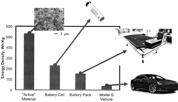
from an analysis of electric cars. As shown in figure 4, the theoretical energy density
of the active materials used in Tesla's batteries is 533 Wh/kg, taking the capacity and
voltage of the NCA/graphite redox couple. This corresponds to the energy density of an
'ideal' battery made only with the active materials involved in the LiNiO.8CoO.1 5Alo.0 5O2 +
C6 , Nio.8Co0.15Ao.0 502 + LiC6 reaction. Packaging these materials into a battery
requires the addition of 'inactive' materials such as current collectors, separator, electrolyte
and cell casing required for battery operation but not directly involved in storing energy.
These materials lower the energy density at the cell level to about 230 Wh/kg [ P , ]. The
battery pack, composed of thousands of cells, a cooling system and a battery management
system, has an energy density of about 160 Wh/kg. [i11,
1
x] Meanwhile the vehicle-level energy density, taking the battery pack capacity divided by the curb mass of the unloaded600 S500 3 400 300 200 W 100 0
"Active" Battery Cell Battery Pack Model S
Material Vehicle
Figure 4: Progressive reduction in the energy density of the energy-storing components of a Tesla model S. Battery active materials refer to the NCA/graphite redox couple used in the battery. Battery Cell is based on Panasonic 18650. Battery pack is based on an 85 kWh Tesla Model S pack. Model S vehicle is based on the energy in the 85 kWh pack divided by total vehicle mass. Each packaging step introduces more inactive material which is not involved in energy storage. Using structural battery, energy storage materials may replace some of the inactive components and increase the overall vehicle energy density.
This demonstrates that there is in principle scope to replace components of the
auto-mobile with energy storing material, in order to increase vehicle-level energy density using
a structural battery. Figure 5 analyzes the feasibility at a subsystem level, showing that
in principle about 36% of the vehicle mass might be replaced. It should be noted that
the battery pack shown in these pie charts has an energy density of about 160 Wh/kg, -3 pm
whereas the structural battery may have an energy density closer to the cell level of about
230 Wh/kg. Furthermore, because the structural battery will have a high surface area, it is envisioned to not require heavy cooling systems as cells in battery packs do. This could
increase the range of the vehicle by a factor of two to three, without requiring advances in
active materials level energy density.
(a) Electrical Exterior Misc Interior (b) Potential Muifunctioal Mass Fraction: 36% Battery Pack
Frame, Interior and Exterior
Figure 5: Mass breakdown of a Model S in order to evaluate the feasibility of replacing components of the vehicle with structural battery. (a) Subsystem mass fractions of Model S components, from [5 ]. (b) Mass fraction that might be replaced in principle.
1.4. Structural batteries in airborne vehicles
Structural batteries have a substantial potential to impact airborne vehicles. Following
t= ( EB '\ (pSCL ) 1/2
t= M3/27 2CD2 " 1
Here, te is endurance (ie flight time), EB is the energy contained in the battery system
(multiplied by the round-trip efficiency, which will be ignored for this analysis), M is the total system mass, p is the density of air, S is the wing area, CL and CD are the lift and
drag coefficients, and ip is the propeller efficiency. If we modify this vehicle by including
a structural battery but maintain its aerodynamic shape, we can take EB(x) and M(x) to
be functions of the amount of multifunctional material included. Differentiating these, we
get:
dte dEB 1 3 EBM /2 dM /
17p
dx dx M3/2 2 WM - 2C.2, )
Making a finite design change Ax, we can normalize the change in endurance Ate by
the initial endurance to get:
Ate AEB 3 AM (2)
te E 2 M
Equations 1 and 2 quantify how design decisions on battery mass and weight affect flight time. In particular, we can break the total vehicle mass down into battery mass and the mass of non-energy-storing systems:
MAotal = MO + MBatt
In which case, battery energy is the product of battery mass and the specific energy
CSp-EB = Csp -MBatt
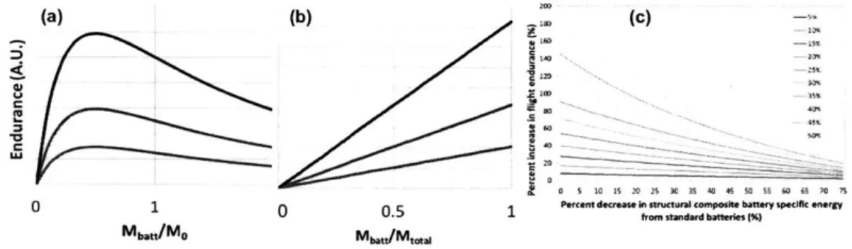
This makes it simple to calculate the dependence of edurance on battery mass. Two
cases for this are shown in figure 6. In figure 6a, endurance is shown as a function of the ratio
of battery mass to Mo. Interestingly, endurance shows a maximum at MBtt/MO=0.5. Thus,
increasing the battery mass fraction beyond 33% of total vehicle mass lowers endurance.
This follows from equation 2, which shows that fractional increases in mass fraction are
more heavily weighted (by 3/2) than fractional increases in stored energy. However, using
a multifunctional material to replace structural mass with energy storing mass increases
endurance. This is shown in figure
6b,
which assumes that total vehicle mass remains constant and the mass fraction devoted to battery simply increases (at constant Csp).(a) 0 (b) (c) 140 C 11o I"i 0 1 Mb.U/MO 0.5 Ma,,"/Mmw 2'
Pwcentdecmao in smtnjuta comro40te batory opolfC .n"r 1
~from~
standard battrie (%)Figure 6: Effect of structural battery addition on UAV endurance for winged vehicles. (a) At constant specific energy, endurance decreases when the ratio of battery mass to non-energy-storing mass exceeds one half. (b) At constant total vehicle mass, replacing structural mass with multifunctional energy storing material increases range. (c) An anal-ysis of the effect of structural battery design on a Raven UAV, from [ ;i], for different fractions of total mass replaced by structural battery.
Work has been done in the literature applying these principles to UAV design [1,
-1 ]. Figure 6 shows the result of an analysis on the Raven UAV, a popular military
vehicle manufactured by Aerovironment. [> ]. They estimate that it should be possible to
increase endurance in this UAV design by more than a factor of two (ie. 100% increase).
2.
Strategies for structural energy storage
In the existing literature, several strategies exist for taking advantage of a structural energy
storage architecture. Published work spans approaches involving no modification to the
battery architecture at all but simply transferring load to off-the-shelf architectures, to
transferring load to current collectors, to modifying actual battery electrodes to bear load.
Extensive work has been done on the use of carbon fiber as an anode for structural batteries
and as an electrode for structural capacitors. In addition, much has been published on
modifying polymers in order to serve as binders in structural batteries. This section will
provide an overview of all these strategies, then introduce the Structural Ceramic Battery
(SCB) design and highlight its benefits.
2.1. Transferring load to conventional batteries
Mechanical and Aerospace engineers have long shown interest in the structural battery
concept. A strategy they have used to achieve structural energy storage is to simply design
vehicles to transfer load to off-the-shelf batteries. Research in this area doesn't require
re-design of the actual battery electrodes or impose any electrochemical trade-offs.
Aerospace engineers have historically shown particular interest in this approach, due to
the high cost of launching satellites into space and the resulting benefit of any technology
that could be used to lower their mass. One example was developed at the University
(a), lithium polymer batteries were purchased and built into panels. A similar design was
demonstrated at the National University of Defense Technology using foam core sandwich
panels with similar lithium polymer cells.
[7
More recent work has shown that batteries might be used to absorb mechanical energy
in the case of an electric car crash, by connecting the cells in a 'butterfly' arrangement
designed to function as a crumple zone as shown in figure 7 (b-c) [1 731. The goal of this
architecture is to transfer load to cells and joints between them so that a crash can occur
without rupturing the cells. If successful, this architecture will lower the mass of structural
materials required in a vehicle crumple zone. A similar strategy incorporated batteries
into a vehicle crumple zone by placing sacrificial tubes between the cells. [.
3]
This was considered a multifunctional, energy-absorbing battery pack.(a)
Figure 7: Strategies for using conventional batteries as structural elements. (a) Spacecraft sandwich panels were developed to transfer load to off-the-shelf batteries as detailed in [ 1 , ]. (b-c) Batteries were connected in a 'butterfly' architecture in order to safely
absorb mechanical energy in a vehicle crumple zone. The structure is shown in both the initial configuration (b) and after absorbing load (c). Scale bars are 2cm. [173]. (d) A prototype of the Wasp UAV employing custom-shaped Lipo cells as structural wing skins. [160,1(;J]
This strategy has also been applied to Unmanned Aerial Vehicles (UAVs). Prototypes
of the Wasp UAV employed shaped cells using a PVDF-HFP binder developed by Bellcore
as shown in figure 7 (d) [
60].
Publications noted that the costs associated with custom cell designs were a significant barrier to adoption of this strategy [ I(]. Clearly, any technologyaiming to make structural batteries commonly used will require facile production methods
in order to lower the unit costs associated with custom runs. It should be noted that the
Wasp is now a production UAV manufactured by Aerovironment, and that the production
version does not feature a structural battery design. My conversations with an engineer
at Aerovironment pointed to the complication and cost of manufacturing outweighing the
benefit in this case. Improvements in the performance of structural batteries and their
manufacture may change the cost-benefit calculus in the future.
Other work showed that thin film batteries could be embedded directly into carbon
fiber reinforced plastic sheets [11
2].
These cells were able to withstand the processing conditions necessary to produce full composites and cycled normally when the compositewas subjected to 450 MPa tensile load.
It should be noted that this strategy, to transfer load to off-the-shelf batteries, is not
on the face of it unlikely to provide significant performance improvements. Batteries that
are not optimized as structural elements should not be expected to bear much load, or
to be efficiently integrated into vehicles. The theoretical performance improvement of a
structural battery strategy derives from electrode components bearing structure, and to the
their full potential. The Wasp project, for example, projected only a 26% performance
improvement [1.60] by transferring load to an off-the-shelf battery, far short of the projected improvements discussed above.
2.2. Transferring load to current collectors
A recent structural battery strategy, explored as part of the ARPA-E RANGE program, is to transfer mechanical load to the current collectors of a battery.
[
1 , 7,] This strategy lies mid-way between a true structural battery in which electrodes are re-designed to bearload, and an off-the-shelf battery used for structure as discussed above.
The design, shown in figure 8, includes a conventional battery stack fabricated in a
metal panel. Current collectors of 9
pm
thick copper (negative) and 15pm
thick aluminum(positive) foil were coated with conventional NMC and graphite electrodes made using
PVDF binder. These were mechanically attached to the battery casing so that external
loads would be transferred to these foils. The stack was laminated together with Celgard
separator, and the entire battery panel was sealed using epoxy. After fabrication and
(a) rwn j~y Ssakci are.r Maltzml, Cuhode Fillng Sep"Sto Port Anode Al Ro x * (c) Face skin Battery materials Adhesive (b) Face skin (a]hod) tninal Applied load -C-channel Ruker (30 can long)
PEI end plug
El- rolyte filing por ($ugged)
Figure 8: A design for transferring external load to the current collectors of a battery. [ 19] (a) The basic design, showing parallel battery layers with current collectors mechanically bonded to a metal casing. (b) This battery was loaded in the plane of the current collectors during testing. (c) A cross-section showing the layers of battery material in this prototype. (d) The finished prototype forms a panel that might be integrated as a load-bearing element of vehicle structure.
This design achieved an energy density of 102 Wh/kg and a bending stiffness of 1995
N/mm.
[
J
Three-point bending results were not significantly affected by the addition of electrolyte, and performance of these tests did not substantially affect electrochemicalproperties.
This design exhibits some substantial benefits. It is clearly compatible with a wide
den-sity and mechanical properties (though less than half the energy denden-sity of state-of-the-art
battery cells). However, there are some theoretical and practical drawbacks to this work.
Firstly, because load is being transferred to the current collectors and not the electrodes,
the structural performance of this design will be limited by the current collector volume
fraction. This inherently poses a trade-off between electrochemical and mechanical
per-formance. Secondly, the cell may only be loaded in the transverse direction as shown in
figure Sb. In directions perpendicular to the plane of the current collectors, they will not
effectively increase the rigidity of the battery. The third concern is the manufacturability of
these cells in arbitrary shapes. It is envisioned that during the design process, engineers will
require cells of many shapes to be produced in order to evaluate structural battery enabled
vehicle prototypes. It is not obvious that this battery design could be easily manufactured
to accommodate arbitrary shapes, particularly curved shapes such as those required for
UAV wings or automotive panels.
2.3. Carbon fiber electrodes
As graphitic carbon fiber (CF) is a high-performance structural material and graphite
is commonly used as a Lithium Ion Battery (LIB) negative electrode, it is natural to
investigate CF as a multifunctional LIB active material. Much of the work done to date
on structural LIBs has employed this strategy.
Extensive work has been done evaluating the fundamental electrochemical and
the reversible capacity of carbon fiber in a LIB half-cell is typically about 100-150 mAh/g
depending on the variety of carbon fiber used. [
7,
.] This is in contrast with atheoret-ical capacity of 372 mAh/g, or about 34% of theorettheoret-ical. This capacity is plotted against
specific strength in figure
9b.
The electrochemical origin of the relatively low specific capacity of graphite fiber is an
interesting area of debate. One potential origin is lithium diffusion into and out of the
fibers limiting electrochemical utilization. As shown in figure 9c, the diameter of
individ-ual carbon fibers is under 10pm. This is below the average particle diameter of graphitic
mesoporous carbon microbeads used in batteries, with a median value of 17pm. [2
1].
How-ever, as in-plane lithium diffusivity in highly oriented graphite is four orders of magnitudehigher than diffusivity perpendicular to the graphitic planes [I I], orientation of graphite
sheets parallel to the axis of CF may play a role in preventing full graphite utilization. As
the tensile strength of graphite is also anisotropic, and higher in the plane of the graphite
sheets [ A, the orientation of graphite along a carbon fiber imposes a trade-off between
mechanical strength and electrochemical charge transport. Studies measuring the
diffusiv-ity of Li+ in CF have indeed shown a variation of about four orders of magnitude from
10-6cm2/s to 10-10cm2/s, [ , ) , )6 , J T] suggesting that varying degrees of orientation play a substantial role in determining diffusivity.
A second origin for the poor electrochemical utilization of CF may be the area-specific loading of these materials. A 3K weave T300 tow, among the highest performing CF
is a high active material loading, corresponding to an area specific capacity of 2.9 mAh/cm2 at a nominal capacity of 150 mAh/g. This corresponds closely to the area specific capacity
of commercial electrodes, ['] with a maximal area specific capacity dictated by lithium
ion diffusivity through battery electrode and separator layers. If this weave could achieve
higher active material utilization at low rates, therefore, it would not be able to achieve
higher than 150 mAh/g at typical cycling rates. Thinner carbon fiber weave with a lower
loading may thus be better optimized for structural battery performance. It should be
noted that in the case of carbon fiber used as a structural element, the fiber is coated
in a non-lithium-conducting epoxy. This layer was not present in the half cells evaluated
in figure 9, and add an additional barrier to the practical use of CF as a multifunctional
negative electrode active material. Development of lithium conductive adhesives will be
discussed in the following section.
0
Activale~d ("=#Jew Fbr 42 22j;)3o (a) AeirgelPaper(Gfade II) .00 0PAN (b)
APAN lit U0004') ant
30 OPANx Mr(T-300 1k) + Nanotub Pper (HPNT) 2x PichbFber(XN15) ! 20 ag - Ganarrapbkt 0p 00 '010 20 30 40 0 10000
Cycle Nunter pcrTe e tei{Pgjn)
Figure 9: Evaluation of carbon fiber (CF) used as a negative electrode in LIBs evaluated in [.15]. (a) Cycling data of various CFs in a half cell, cycled at 1.7pA/cm2. The material achieves about 34% of the 372 mAh/g theoretical capacity. (b) Specific capacity of various CFs plotted against specific strength. (c) A scanning electron micrograph of an individual carbon fiber shows that the fiber diameter is under 10pm.
Several published projects have used carbon fiber negative intercalation electrodes in
structural LIBs. Some of the earliest strucutral battery work, done at the Army Research
Lab, used this architecture. [1 4] To date, the highest performing packaged structural
battery cell uses such an architecture as well, [32] achieving 116 Wh/kg and 35 GPa stiffness
with a carbon fiber negative electrode, a lithium iron phosphate positive electrode, and a
gel electrolyte. It should be noted that while energy density is given, more extensive
electrochemical data are not.
Another interesting tactic that uses a CF weave is to electrodeposit a separator directly
onto the CF tow. This has been demonstrated
[
:]
and even used to make an interpen-etrating battery by subsequently adding positive electrode slurry.[
,j
This is a novelapproach that may be built upon in the future development of structural LIBs.
Overall, the performance of CF as a structural battery material is excellent from a
structural point of view but mediocre electrochemically. This is partially due to the low
(under 45%) electrochemical utilization of graphite in carbon fiber under reasonable cycling conditions. In addition, it should be noted that a structural battery design relying on a
single active material will not be able to make substantial electrochemical performance
improvements as batteries improve. A structural battery architecture is desired which is
able to accommodate new active materials as they become available, improving in specific
2.4. Structural polymer-based binders
A major focus in structural energy storage work has been to produce a polymeric binder material that is able to contribute to battery structure while promoting ion transport.
These two requirements are somewhat at odds.
One of the factors putting ion transport and structural integrity at odds is the
rela-tionship between ionic mobility and configurational entropy of the polymer. The
addi-tion of plasticizers has been well established in the literature to increase ionic
conductiv-ity.
[,
4, , ] While this makes intuitive sense, as plasticizers increase the configu-rational entropy and mobility of polymer chains and would thus be expected to increasethe mobility of Li+ ions, plasticizers also have the effect of softening the polymer they are
added to. This decrease in softness results in a polymer less able to bear load. One
poten-tial method for breaking this trade-off between mechanical stiffness and ionic conductivity
is to employ a 'solid plasticizer', or solid particles which act to stabilize the amorphous
phase of the polymer electrolyte, [2
1, 0, 137]
and 'nano-fillers', or solid particles that act to simply increase the stiffness of the polymer by forming a composite and improveconduc-tivity through favorable ionic surface interactions. [6,7, I i I ., I ; I] This strategy has been
considered for structural energy storage applications, but it was noted that the resulting
tensile strength of these composite structures remains low. [1A]
Extensive work has been performed at Imperial College London using epoxy-based
superca-pacitors.
[
, ')fU, , ]. The original motivation of this work was to use an established structural binder for carbon fiber, and modify the material in order to better conduct Li+ ions. It should be noted that common organic electrolyte solvents soften epoxy, [!95] sothat ionic liquid electrolytes are preferred as the ion conducting phase. (a)(C)
UqmW escra" Er
Epmoy Nisi~n ILbased Sokdion of
W
T1(R) cet lytt RI'L+0LY1 EtMI -FS 1
IIL+UY) Epa-y
M' hMW tEoooni IE3 01 Ift
Figure 10: Synthesis and evaluation of bicontinuous epoxy-ionic liquid electrolytes. (a) This class of materials is formed by mixing epoxy and an ionic liquid, with following phase separation during curing. [ 1] (b) The resulting microstructures exhibit intricate multiscale morphologies, as shown using SEM micrographs. [ 12] (c) As is common in multifunctional materials, a trade-off is observed between materials properties. In this case, a trade-off is noted between stiffness and ionic conductivity. [141]
Figure 10 demonstrates the synthesis, morphology, and characterization of these bicon-tinuous electrolytes. As shown, the epoxy and the conducting phase are mixed together and then phase separate in order to form a bicontinuous network as the epoxy cures. It was shown that by controlling the degree of miscibility through composition, the morphology can be controlled. [112] In general, increasing amounts of epoxy will lead to stiffer
compos-ites with better mechanical properties. By contrast, higher volume fractions of the ionic liquid electrolyte will improve ionic conductivity. This trade-off has been quantified in
figure 10c. As shown, the best composite in this system exhibits about lox lower Young's
modulus than the pure epoxy and lOx lower ionic conductivity than the pure ionic liquid. (a)S''X'Y' * (U CO " (b) (C) Cathode VW UNd00d Cwaon M&MMibW
(a)
s,"Ma
" -m (e-g. (b)O 1 )2Fibers 4Asmesiams
Cathode- isa2g
Separator- .... ... Cwbon IMao or
Anode
-Anode Actnte Mateee Carbon
(e0g. gn"phfte Nbers 01 20 .6 so N 100 120 140 160 0
cp."oa ,,atog.. 0 5 10 is 20
Figure 11: A polymer-based structural battery. [90] (a) The architecture of this battery, including an LCO positive electrode and a graphite negative electrode. Poly(ethylene oxide) is used as a polymer gel electrolyte, PVDF as a binder, and carbon fibers are used as structural members. (b) The discharge capacity of this structural LCO electrode compared to a conventional electrode. (c) A tensile test comparing the mechanical properties of the structural electrode to a conventional electrode.
The highest-performing 'true' structural battery (meaning that load is transferred to
electrodes) for which we have tensile strength data uses a polymer electrolyte. [9
]
The performance of this battery is shown in figure 11. In this design, PVDF is used as a binderand PEO is used in addition as a polymer gel electrolyte. The increased strength compared
to a conventional electrode comes from using high molecular weight PVDF, and improving
the electrode strength by the use of carbon fiber additives.
As shown in figure 11b, the discharge capacity of the structural battery electrode is
only about 60% that of the conventional electrode. This may be due to lower electronic
conductivity. The increase in electrode ultimate tensile strength (UTS), shown in figure


![Figure 7: Strategies for using conventional batteries as structural elements. (a) Spacecraft sandwich panels were developed to transfer load to off-the-shelf batteries as detailed in [ 1 , ]](https://thumb-eu.123doks.com/thumbv2/123doknet/14159936.473109/34.917.141.737.573.719/strategies-conventional-batteries-structural-elements-spacecraft-developed-batteries.webp)

![Figure 9: Evaluation of carbon fiber (CF) used as a negative electrode in LIBs evaluated in [.15]](https://thumb-eu.123doks.com/thumbv2/123doknet/14159936.473109/40.917.112.740.605.787/figure-evaluation-carbon-fiber-negative-electrode-libs-evaluated.webp)


