HAL Id: ensl-00542396
https://hal-ens-lyon.archives-ouvertes.fr/ensl-00542396
Preprint submitted on 2 Dec 2010
HAL is a multi-disciplinary open access
archive for the deposit and dissemination of
sci-entific research documents, whether they are
pub-lished or not. The documents may come from
teaching and research institutions in France or
abroad, or from public or private research centers.
L’archive ouverte pluridisciplinaire HAL, est
destinée au dépôt et à la diffusion de documents
scientifiques de niveau recherche, publiés ou non,
émanant des établissements d’enseignement et de
recherche français ou étrangers, des laboratoires
publics ou privés.
FPGA-Specific Custom Arithmetic Datapath Design
Florent de Dinechin, Bogdan Pasca
To cite this version:
Florent de Dinechin, Bogdan Pasca. FPGA-Specific Custom Arithmetic Datapath Design. 2010.
�ensl-00542396�
FPGA-Specific Custom Arithmetic Datapath Design
LIP Research Report RR2010-34
Florent de Dinechin, Bogdan Pasca
LIP (ENSL-CNRS-Inria-UCBL), Ecole Normale Superieure de Lyon 46 all´ee d’Italie, 69364 Lyon Cedex 07, France
Email:{florent.de.dinechin, bogdan.pasca}@ens-lyon.org
Abstract—This paper presents FloPoCo, a framework for easily designing custom arithmetic datapaths for FPGAs. Its main features are: an important basis of highly optimized arithmetic operators, a unique methodology for frequency-directed pipelin-ing the designed circuits and a flexible test-bench generation suite for numerically validating the designs. The framework was tested for designing several complex arithmetic operators, this paper presenting the architecture and results for the exponen-tial operator. Synthesis results capture the designed operator’s flexibility: automatically optimized for several Altera and Xilinx FPGAs, wide range of target frequencies and several precisions ranging from single to quadruple precision.
Keywords-FloPoCo; framework; arithmetic circuit; pipelining; flexibility;
I. INTRODUCTION
In the last years the trend of using FPGAs for prototyping ASICS has shifted towards FPGAs as application accelerators. There in a wide range of applications that can benefit FPGA acceleration but the best-suited candidates applications are intrinsically parallel and require complex and exotic arithmetic operations using custom precisions.
The potential FPGA speedup over microprocessor systems can go beyond 3 orders of magnitude, depending on the application. However, translating even the best acceleration candidate into an optimal FPGA design is a tedious task. The first attempts for application acceleration using FPGAs boiled down to a manual, low-level circuit description. FPGA tools have come a long way since then, but even today, although laborious, describing circuits using low-level primitives is still done performance-critical circuit parts.
At the other end of the spectrum, new products targeting portability and productivity were developed [1], [2], [3], [4], [5]. These products are capable of automatically generating circuit descriptions for algorithms described in subset of the C language. Out of these tools, only [1] and [4] are capable of dealing with floating-point numbers. Numerous compiler optimization techniques are implemented, but most of the time the result is significantly slower and larger than manual design. Arithmetic datapath design for microprocessors includes several constraints among which the fixed operators imple-mented in hardware (for floating-point: +−, ∗) and their working precisions, usually single-precision (SP) and double-precision (DP). Matching these operators and the available precisions will generally yield a good design. Trying to optimize the datapath using exotic precisions will bring no improvement.
Due to their reconfigurability, FPGAs have virtually no constraints. However, in order to benefit from the last drop of performance the user must understand the problem well enough so he can give a rough bound on the output precision. From this specification, the circuit can be implemented work-ing with non standard operators at custom precisions yieldwork-ing significant speedups over traditional design [6].
We seek to provide an extensible open-source framework for efficiently building arithmetic pipelines on FPGAs. It can be seen as a hybrid between the two ends of the spectrum, automatizing parts of the design process of high-performance arithmetic operators. The development effort of the arithmetic pipeline will be a parametrized design in: input/output preci-sion, deployment FPGA and objective frequency.
II. ARITHMETICOPERATORS
In this work we consider arithmetic operators as being circuits that can be described by a functionf (X) = Y where X = x0, ..., xi−1 is a set of inputs and Y = y0, ..., yj−1 is
a set of outputs. Any sequential code without feedback loops performing some computations fits this description. Take for example the circuit performing the complex multiplication: (a+bj)(c+dj). The circuit inputs are a, b, c, d and the output is the pairr = ac − bd, i = ad + bc. As it can be seen in further sections, the restriction to this class of circuits allows for a finer modeling of arithmetic circuits. A simple extension to the introduced framework will allow us to model circuits having feedback loops.
A. FPGA-specific arithmetic operator design
Two of the factors characterizing the quality of arithmetic operators on FPGAs are circuit area and operating frequency. Unfortunately, there is a monotonic dependency between the two: the faster a circuit is, the more resources it takes. As circuit frequency f is part of the project’s specifications, our job as designers is to build the smallest circuit matching this frequency. The task gets even more complex if we introduce
productivityin the equation.
One solution is to use high-performance off-the-shelf IP cores for modeling the circuit. This solution will give the correct performance at the expense of pipeline depth and
circuit areaas the obtained frequency is usually overestimated. Another way to do this is assembling custom components built for the same frequencyf . The circuit proposed in [7] for
low abstraction high abstraction speedup productivity
our framework
Fig. 1. Productivity in porting applications to FPGAs and the relative performance of these circuits provided the different levels of abstraction are provided for circuit description
evaluatingx2+y2+z2in DP uses a custom 3-input FP adder1
and squarers. The circuit consumes 40-50% less logic and 25-33% less embedded multipliers on a Xilinx Virtex4 device than assembling high-performance off-the-shelf IP cores from Xilinx Coregen [8].
The target of the FloPoCo is to cover a broad range of abstraction levels, allowing the user to obtain the required performances as productively as possible, without overengi-neering the solution. For complying with these demands, our framework should:
• provide quality implementations of all the basic
off-the-shelf additonSizeblocks available in commercial core generators and more
• provide the mechanisms for easily connecting and
syn-chronizing these blocks
• enhance productivity by employing reusability. Each
op-erator described using this framework will be part of an
available operatorsbasis.
• be expressive enough to capture low-level FPGA-specific
architectural optimizations when needed
• employ frequency-directed pipelining for minimizing
cir-cuit area and pipeline depth
• encourage parametric description of circuits so they can
easily be retuned to changing precision requirements
• allow to easily retarget existing operator descriptions to
new FPGAs.
In a more visual representation, Figure 1, FloPoCo should be able to cover a whole range of abstraction levels in the circuit description allowing much better productivity than hardware description languages while being able to offer the same set of performances.
1The classical implementation of FP adders has two paths, one of which is
for the case of subtraction. As the inputs are all positive this path is manually trimmed-out at design time.
III. THEFRAMEWORK
A. Initial off-the-shelf tools
1) Adder: Integer addition is used as a building block in many coarser operators. In hardware description languages (HDL) addition is expressed as ”+” and is implemented as a ripple-carry adder. Although FPGAs are enhanced to better support this type of adder, long additions require pipelining for reaching high frequencies. Examples which require large adders include integer multipliers, most FP operators2, and
modular adders used in some cryptographic applications3. FloPoCo offers three different implementations for pipelined adders [10]. In the multidimensional space (f ,FPGA,circuit area) our framework transparently chooses the best architec-ture for a given scenario.
2) Multiplier: Multiplication is a pervasive operation, and in an FPGA it should be adapted to its context as soon as this may save resources. Recent FPGAs embed a large number of Digital Signal Processing (DSP) blocks, which include small multipliers.
The automated generation of larger multipliers using the embedded multipliers and adders present in the DSP blocks of current FPGAs can be expressed as a tiling problem, where a tile represents a hardware multiplier, and super-tiles represent combinations of several hardware multipliers and adders, making efficient use of the DSP internal resources [11]. This technique allows building high performance mul-tipliers while minimizing DSP block count. Reducing DSP-block count can also be implemented using the Karatsuba-Ofman algorithm which trades multiplications for additions. The available multipliers using this technique have the DSP cost reduced from 4 to 3, from 9 to 6, or from 16 to 10 on a Virtex4 FPGA [12].
Our framework offers all these types of multipliers, there-fore offering the designer a large space of different trade-offs between latency, logic and DSP count.
3) Squarer: Squaring is fairly common in FPGA-accelerated computations, as it appears in norms, statistical computations, polynomial evaluation, etc. A dedicated squarer saves as many DSP blocks as the Karatsuba-Ofman algorithm, but without its overhead. FloPoCo implements squarers as presented in [12]. By using squarers instead of off-the-shelf Coregen Multipliers the evaluation ofx2+y2+z2was reduced
from 27 to 18 DSPs for DP and from 20 to 9 DPSs for SP [7].
4) Truncated Multipliers: Truncated multipliers [13] dis-card some of the lower bits of the mantissa to save hardware resources. For a FP multiplier, the impact of this truncation can be kept small enough to ensure last-bit accuracy (or faithful rounding) instead of IEEE-754-compliant correct rounding. This small accuracy lost may be compensated by a larger man-tissa size. However, it is also perfectly acceptable in situations
2In floating-point, the demand in precision is now moving from double
(64-bit) to the recently standardized quadruple precision (128-bit format, including 112 bits for the significand) [9]
3In elliptic-curve cryptography, the size of modular additions is currently
where a bound on the relative error of the multiplication is enough to ensure the numerical quality of the result. This is for instance the case of polynomial approximation of functions: it is possible to build high-quality functions out of truncated multipliers [14]. The implementation of truncated multipliers is an important step towards efficient implementations of elementary functions up to quadruple precision on FPGAs. FloPoCo offers the implementation of truncated multipliers as described in [11].
5) Constant Multiplier: Multiplication by a constant is a pervasive operation. It often occurs in scientific computing codes, and is at the core of many signal-processing filters. It is also useful to build larger operators: architectures for exponential, logarithm and trigonometric functions [15], [16] all involve multiplication by a constant. A single unoptimised multiplication by 4/π may account for about one third the area of a dual sine/cosine [15]. FloPoCo’s implementation of constant multipliers, both integer and correctly rounded FP is that presented in [17].
6) Function Evaluator: Polynomial approximation is a very general technique for the evaluation of a wide class of numeri-cal functions of one variable. FloPoCo provides an architecture generator that inputs the specification of a function and outputs a synthesizable description of an architecture evaluating this function with guaranteed accuracy. Our current implemen-tation [14] improves upon the literature in two aspects: it uses better polynomials, thanks to recent advances related to constrained-coefficient polynomial approximation [18], and it refines the error analysis of polynomial evaluation to reduce the size of the multipliers used.
B. Synchronization mechanisms
Arithmetic operators as defined in Section II have no feedback loops. Such an operator can be seen as a flow of operations propagating from the inputs towards the outputs. In order to obtain high throughputs these operators are deeply pipelined. Such operators can be obtained by assembling elementary operators built for the same frequency f and synchronizing the datapath accordingly using registers. As the pipeline depth of sub-components is a depends on the target FPGA, frequency f and precision, generic synchronization mechanisms are required in order to connect these compo-nents.
Hardware circuits usually have several several parallel ex-ecuting threads which may interact. HDLs, being concurrent languages4 make it natural to describe combinatorial circuits of this type. The triviality comes from the fact that all compu-tations are performed at the same clock cycle. For pipelined designs one has to describe the computations performed at each clock cycle. The synchronization between signals is a tedious and error-prone task. Moreover, minor modifications to the pipelining depth of components usually leads to syn-chronization problems.
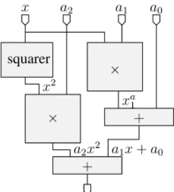
Say for instance that we need to parallelly evaluate the second-degree polynomial: a2x2 + a1x + a0 (Figure 2).
4statements are executed concurrently
squarer x × a1 × a2 a0 + + a2x2 xa1 x2 a1x+ a0
Fig. 2. Parallel evaluation of the polynomial a2x2+a1x + a0
When performing the addition a2x2+(a1x + a0) we need
to synchronize the two input signals. The pipeline depths of the two signals are d1 = dsquarer + dmultiplier and
d2= dmultiplier+ dadder. This yields three cases:
d1> d2 need to delay the FPAdder output with d1− d2
cycles
d2> d1 need to delay the FPMultiplier output withd2− d1
cycles
d1= d2 computation can be performed directly as the two
signals are already synchronized.
Formally, when needing to synchronize several signals the procedure consists in determining the maximum pipeline depth of all signals and delaying the rest for the corresponding clock cycles.
Figure 3 presents the FloPoCo parametric code for the floating-point version of this circuit. The instantiated FP primitives, FPSquarer, FPMultiplier and FPAdder are also parametrized function of target FPGA (the target parameter), exponent width (wE) and fraction width(wF ); The synchro-nization between the different threads is done using two functions:
syncCycleFromSignal(”s”) : advances the current cycle in describing the circuit to the declaration cycle of signal ”s” (production cycle)
setCycleFromSignal(”s”) : sets the current cycle to the declaration cycle of signal ”s”. This is useful when describing new threads for which the current cycle is less than our current active cycle (Figure 3, line setCycleFromSignal("a1");)
C. Sub-cycle accurate data-path design
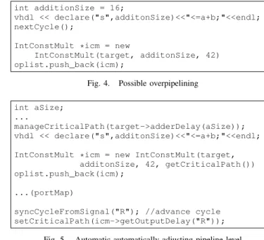
All basic FloPoCo operators have flexible pipelines, adapt-ing to the user specified frequency, target FPGA proper-ties and input/output precisions. By registering the inputs of these components we guarantee that the critical path remains smaller than 1/f . However, this is not optimal. Consider the following case depicted in Figure 4. For the cases when additionSize and f are small enough registering the addition in not needed which leads to an overpipelined circuit. In order to avoid overpipelining and therefore wasting resources IntConstMultiplier should be able to adapt its
int wE; int wF; addFPInput("X",wE,wF); addFPInput("a2",wE,wF); addFPInput("a1",wE,wF); addFPInput("a0",wE,wF);
FPSquarer *fps = new FPSquarer(target, wE, wF); oplist.push_back(fps);
inPortMap (fps, "X", "X"); outPortMap(fps, "R", "X2"); vhdl << instance(fps, "squarer");
syncCycleFromSignal("X2");// advance depth nextCycle();//register level
FPMultiplier *fpm = new FPMultiplier(target,wE,wF); oplist.push_back(fpm);
inPortMap (fpm, "X", "X2"); inPortMap (fpm, "Y", "a2"); outPortMap(fps, "R", "a2x2");
vhdl << instance(fpm, "fpMuliplier_a2x2"); describe the second thread
setCycleFromSignal("a1"); -- the current cycle = 0 inPortMap (fpm, "X", "X");
inPortMap (fpm, "Y", "a1"); outPortMap(fps, "R", "a1x");
vhdl << instance(fpm, "fpMuliplier_a1x"); syncCycleFromSignal("a1x");// advance depth nextCycle();//register level
FPAdder *fpa = new FPAdder(target, wE, wF); oplist.push_back(fpa);
inPortMap (fpm, "X", "a1x"); inPortMap (fpm, "Y", "a0"); outPortMap(fps, "R", "a1x_p_a0");
vhdl << instance(fpm, "fpAdder_a1x_p_a0"); join the threads
syncCycleFromSignal("a1x_p_a0");//advance syncCycleFromSignal("a2x2");//possibly advance nextCycle();//register level
inPortMap (fpm, "X", "a2x2"); inPortMap (fpm, "Y", "a1x_p_a0"); outPortMap(fps, "R", "a2x2_p_a1x_p_a0");
vhdl << instance(fpm, "fpAdder_a2x2_p_a1x_p_a0"); syncCycleFromSignal("a2x2_p_a1x_p_a0");
vhdl << "R <= a2x2_p_a1x_p_a0; " << endl;
Fig. 3. FloPoCo parametric floating-point description for the circuit in Figure 2
first pipeline stage for the case when there is no reg-ister level at its input. This is accomplished by feed-ing the delay of the previous computation (addition of size additonSize) to the constructor of IntConstMult (target->adderDelay(additionSize)). In turn, Int-ConstMultiplier reports the delay of the circuit at its outputs.
D. Transaction level pipelining
We have presented so far a series of operators and mecha-nisms for facilitating arithmetic operator design having flexible
int additionSize = 16;
vhdl << declare("s",additonSize)<<"<=a+b;"<<endl; nextCycle();
IntConstMult *icm = new
IntConstMult(target, additonSize, 42) oplist.push_back(icm);
Fig. 4. Possible overpipelining int aSize;
...
manageCriticalPath(target->adderDelay(aSize)); vhdl << declare("s",additonSize)<<"<=a+b;"<<endl; IntConstMult *icm = new IntConstMult(target,
additonSize, 42, getCriticalPath()) oplist.push_back(icm);
...(portMap)
syncCycleFromSignal("R"); //advance cycle setCriticalPath(icm->getOutputDelay("R"));
Fig. 5. Automatic automatically adjusting pipeline level
pipelines. In this section we present an automation of these techniques, having an inspiration from database transactions.
In databases, a transaction is unit of work (series of state-ments) that are treated atomically, that is, either they are all executed or the transaction is rolled-back. In our case, a transaction is composed of a number of arithmetic operations starting from a previous register level contributing to the critical path delay. A transaction is valid while the critical path of the operations declared within is≤ 1/f . The condition that makes a transaction invalid gives us the precise position where to insert the register level. In this case a new transaction is started having a delay equal to the delay of the operation which invalidated the transaction.
Figure 5 shows the generic optimal pipelining for the code in Figure 4. The manageCriticalPath() function verifies if the addition delay added to the current critical path exceeds 1/f . If this is true, a register level is inserted automatically and the new critical path becomes equal the adder delay. Otherwise, the critical path is updated with the adder delay.
The getCriticalPath() parameter fed to the
IntConstMultconstructor represents the delay information at the multiplier input. The multiplier has to cope with the new information and adjust the delay of its first pipeline level accordingly.
The last line of code updates the critical path delay at the output of the constant multiplier. If the multiplier architecture ends in a register level, this value will be 0, otherwise this will be the delay of the circuit starting from the last register level in IntConstMult.
E. Reality check: ex
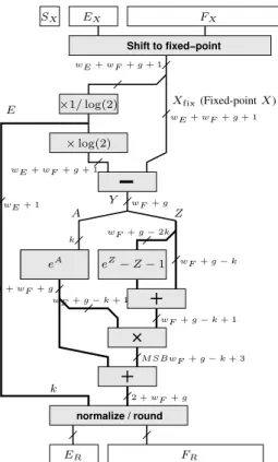
This methodology has been checked on a complex arith-metic operator ex having the architecture depicted in Figure
Shift to fixed−point normalize / round ×1/ log(2) ×log(2) eA eZ −Z − 1 SX EX FX wE + wF + g + 1 ER FR k wF + g − k wF + g − k + 1 M SBwF + g − k + 3 2 +wF + g wF + g k wE + wF + g + 1 Xfix(Fixed-pointX) Y A Z wF + g − k + 1 E 1 +wF + g wE + 1 wE + wF + g + 1 wF + g − 2k
Fig. 6. The generic architecture of ex
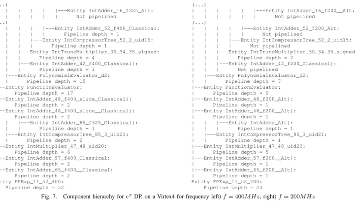
Figure 7 presents in parallel the component hierarchies for two instantiations of this architecture (target frequency of 400MHz on the left and of 200MHz on the right) on a Virtex4 FPGA. The difference in target frequency directly reflects in the pipeline depths of the subcomponents. Assembling compo-nents designed for the target frequency together with with transaction level pipelining, allows reducing the pipeline depth of the architecture for low frequencies, in our case from from 52 levels for 400MHz to to 23 for 200MHz.
Synthesis results are presented in Table I. The fine-grain arithmetic optimizations allowed by FloPoCo makes this operator yield better results for Altera FPGAs, where the proprietary MegaWizard Core Generator from Altera is highly optimized. A whole set of FPGAs are currently supported by FloPoCo including: VirtexII, Spartan3/3E, Virtex4/5/6, StratixII-IV. Once described using our framework, the archi-tecture is optimized for all these targets. Moreover, the circuit is flexible in precision. A large number of different exponential operator instances can be generated for precisions ranging from SP to DP and even up to the newly introduced quadruple precision (QP) in the IEEE754-2800 FP standard [9].
F. Testing
Testing the designed arithmetic circuits is an essential feature of FloPoCo.Arithmetic circuit design starts from its mathematical specification. The architecture is then optimized for FPGA deployment by adjusting intermediate computation size, using specialized operators etc. Once design is finished, our framework is capable of generating all the necessary for
void FPExp::emulate(TestCase * tc) {
/* Get I/O values */
mpz_class svX = tc->getInputValue("X"); /* Compute correct value */
FPNumber fpx(wE, wF); fpx = svX; mpfr_t x, ru,rd; mpfr_init2(x, 1+wF); mpfr_init2(ru, 1+wF); mpfr_init2(rd, 1+wF); fpx.getMPFR(x); mpfr_exp(rd, x, GMP_RNDD); mpfr_exp(ru, x, GMP_RNDU); FPNumber fprd(wE, wF, rd); FPNumber fpru(wE, wF, ru);
mpz_class svRD = fprd.getSignalValue(); mpz_class svRU = fpru.getSignalValue(); tc->addExpectedOutput("R", svRD); tc->addExpectedOutput("R", svRU); mpfr_clears(x, ru, rd, NULL); }
Fig. 8. The emulate() function for ex
testing the implementation results to a series of stimuli against the response of the mathematical model to that set of stimuli. In order to get testing support, each operator has to be annotated with an emulate() function. The purpose of this function is to emulate the behavior of the mathematical spec-ification of the circuit. Say for instance the circuit computes exin floating-point having the architecture presented in figure
6. The emulate() function does not mimic this complex architecture, increasing the probability of doing the same errors in software as in hardware, but mimics the specification: for a given floating-point numberx the output of the value is exfor the given precision. The code of the emulate function
for theex function is presented in Figure 8.
As it can be clearly seen in Figure 8, the specification relies on using multi-precision libraries: 1) MPFR [20] for floating-point operators (+,∗,/, and elementary functions); allows testing the exotic precisions of the operators, facilitating the use of the different rounding modes. 2) GMP [21] for most fixed-point basic operators and internal wrapping operations; facilitates the work with large integer values without concern of overflow.
Test-bench suites can then be generated for all operators im-plementing the emulate function. By default, FloPoCo uses a basic random-number generator to generate input values in the emulate function (tc->getInputValue("X")). The output value(s) (faithful rounding allows two possible results, mpfr_exp(rd, x, GMP_RNDD); mpfr_exp(ru, x, GMP_RNDU) ) for this input is then computed and packed into the the test-case ( tc->addExpectedOutput("R", svRD); tc->addExpectedOutput("R", svRU);).
A list of test-cases form a test-bench. Exhaustive testing, also called soak testing, creates a test-bench which tests all the possible combinations of the inputs. This gives the absolute guarantee that an operator is fully compliant to the
(...) | | | | | |---Entity IntAdder_16_f325_Alt: | | | | | | Not pipelined (...) | | | | |---Entity IntAdder_52_f400_Classical: | | | | | Pipeline depth = 1 | | | |---Entity IntCompressorTree_52_2_uid15: | | | | Pipeline depth = 1 | | |---Entity IntTruncMultiplier_30_34_35_signed: | | | Pipeline depth = 4 | | |---Entity IntAdder_42_f400_Classical}: | | | Pipeline depth = 1 | |---Entity PolynomialEvaluator_d2: | | Pipeline depth = 15 |---Entity FunctionEvaluator: | Pipeline depth = 17 |---Entity IntAdder_48_f400_slice_Classical}: | Pipeline depth = 2 |---Entity IntAdder_48_f400_slice__Classical}: | Pipeline depth = 2 | | |---Entity IntAdder_85_f325_Classical}: | | | Pipeline depth = 1 | |---Entity IntCompressorTree_85_3_uid21: | | Pipeline depth = 2 |---Entity IntMultiplier_47_48_uid20: | Pipeline depth = 6 |---Entity IntAdder_57_f400_Classical: | Pipeline depth = 2 |---Entity IntAdder_65_f400__Classical: | Pipeline depth = 2 Entity FPExp_11_52_400: Pipeline depth = 52 (...) | | | | | |---Entity IntAdder_16_f200__Alt: | | | | | | Not pipelined (...) | | | | |---Entity IntAdder_52_f200_Alt: | | | | | Not pipelined | | | |---Entity IntCompressorTree_52_2_uid15: | | | | Not pipelined | | |---Entity IntTruncMultiplier_30_34_35_signed: | | | Pipeline depth = 2 | | |---Entity IntAdder_42_f200_Classical}: | | | Not pipelined | |---Entity PolynomialEvaluator_d2: | | Pipeline depth = 7 |---Entity FunctionEvaluator: | Pipeline depth = 9 |---Entity IntAdder_48_f200_Alt}: | Pipeline depth = 1 |---Entity IntAdder_48_f200__Alt}: | Pipeline depth = 1 | | |---Entity IntAdder_Alt}: | | | Pipeline depth = 1 | |---Entity IntCompressorTree_85_3_uid21: | | Pipeline depth = 1 |---Entity IntMultiplier_47_48_uid20: | Pipeline depth = 5 |---Entity IntAdder_57_f200__Alt}: | Pipeline depth = 1 |---Entity IntAdder_65_f200__Alt}: | Pipeline depth = 1 Entity FPExp_11_52_200: Pipeline depth = 23
Fig. 7. Component hierarchy for ex
DP, on a Virtex4 for frequency left) f = 400M Hz, right) f = 200M Hz TABLE I
SYNTHESIS RESULTS OF THE VARIOUS INSTANCES OF THE FLOATING-POINT EXPONENTIAL OPERATOR. WE USEDQUARTUSIIV9.0FORSTRATIXIII EPSL50F484C2ANDISE 11.5FORVIRTEXIV XC4VFX100-12-FF1152ANDVIRTEX6 XC6VHX380T-3-FF1923
Precision FPGA Tool
Performance Resource Usage
f (MHz) Latency (A)LUTsLogic UsageReg. Slice DSPs Memory (8,23) StratixIII
Altera MegaWizard 274 17 527 900 - 19 18-bit elem. 0
ours 391 6 832 374 - 2 18-bit elem. 0
405 7 519 382 - 2 M9K
(10,40) Virtex4 ours* (k=5,d=2) 302 43 2498 2219 1500 12 DSP48 5 BRAM Virtex6 ours (k=5,d=2) 488 32 1469 1344 - 10 DSP48E1 3 BRAM
(11,52)
StratixIII
Altera MegaWizard 213 25 2941 1476 - 58 18-bit elem. 0
ours 327256 2915 13071437 37571984 -- 22 18-bit elem. 10 M9K VirtexIV ours* 292187 4529 24542263 23001624 15791283 14 DSP48 5 BRAM (15,112) Virtex6 ours (k=14, d=3) 395 69 8071 7725 - 71 DSP48E1 123 BRAM
specifications. Unfortunately, this type of testing is restricted to only a hand-full of precisions. Generally, it is feasible to test only a small fraction of the total number of tests. Therefore, the problem boils down to choosing the test-vectors which best test the given operator.
For some operators such as fixed-point +, ∗, floating-point ∗, the test-vectors can be generated using the classical random-number generators. The probability of testing all the data-paths of the circuit suffices. Other floating-point operations are more sensitive:
• +. The architecture usually consists of two main
data-paths, one for the case when the difference in exponents is ∈ {−1, 0, 1}. The probability of generating a test-vector which tests this data-path using an random-number generator with a uniform distribution is approximatively 1/85 for single-precision and 1/766 for double-precision.
• ex. The exponential returns zero for input numbers
smaller thanlog(2(2wF −1−1)), and should return + inf for
all inputs larger thanlog((2−2−wF)·22wE−1−(2wF −1−1)).
In single precision the set of input numbers on which a computation will take place is just [88.03, 88.72]. In addition, as for smallx we have ex≈ 1 + x + x2/2, the
exponential will return 1 for all the input x smaller that 2−wF−2. One consequence is that the testing of a floating-point exponential operator should focus on the this range of the input. More details can be found in [19].
FloPoCo offers the possibility of overriding the default be-havior of of filling the test-cases using random-numbers having a uniform distribution. The corresponding function for ex if
given in Figure 9. This new version of the random generator function generates 1/8 truly random inputs, and for the rest of7/8 the exponent is generated such that x ∈ [Xmin, Xmax],
TestCase* FPExp::buildRandomTestCase(int i){ TestCase *tc;
tc = new TestCase(this); mpz_class x;
mpz_class normalExn = mpz_class(1)<<(wE+wF+1); mpz_class bias = ((1<<(wE-1))-1);
/* Fill inputs */
if ((i & 7) == 0) { //fully random x = getLargeRandom(wE+wF+3); } else{ mpz_class e = (getLargeRandom(wE+wF) %(wE+wF+2))-wF-3; e = bias + e;
mpz_class sign = getLargeRandom(1); x = getLargeRandom(wF) + (e << wF) + (sign<<(wE+wF)) + normalExn; } tc->addInput("X", x); /* Get correct outputs */ emulate(tc);
return tc; }
Fig. 9. The function generating the specialized distribution of test-cases for ex
whereXmin= 2−E0 andXmax= (2 − 2−wF) · 22
wE−1−E0 . For the case of the floating-point addition one could decide that testing the two data-paths with the same probability suffices. Implementing this change is trivial, but might not be enough. Consider the extreme case X + (−X). This causes a massive cancellation of the mantissas and is therefore a difficult case to cover. Probabilistically, this has a 1/2wF chances of happening with a uniform distribution.
In order to capture all these corner-cases, FloPoCo allows manually defining a set of standard test-cases which make it possible specify the extreme cases.
G. Framework extensions
1) Managing feedback loops: Up to this point we have constrained our definition of arithmetic operator to functions. In fact, the current implementation of FloPoCo can also manage feedback loops. This is especially important as the accumulation5circuit which falls in this category is considered by many the 5thbasic operation. The subtlety in this case is using a signal which may be declared cycles later. Say for example that the accumulation circuit takes has 5 pipeline stages. The result signal of this accumulation is declared only at cycle 5 in the design, however, this input needs to be fed back to the first cycle, at the accumulator input. As using a signal cycles before it’s declared leads to errors in designs not having feedback loops, at circuit generation time our framework signals to the user, as a warning, the signals having this property. If indeed the signals are feedback signal this may be ignored. Otherwise, the described circuit may not be what the user planed for.
5[22] presents a detailed implementation specific to FPGAs
2) An extension tool for VLSI ALU design: The initial purpose of FloPoCo was to provide a flexible environment for describing purely arithmetic operators for FPGAs. Never-theless, FloPoCo may be extended so to be used in VLSI ALU design. The extension is in fact a simplification of all basic components for the VLSI target. The VHDL code generated for the basic operators will simply be ”+,-,*”.
FloPoCo will be used perform and initial pipelining of the ALU. The code generated will then be passed through VLSI specific tools which replace the ”+,-,*” operators by VLSI-specific instantiations and perform register retiming.
3) Backend for HLS: Our framework can also be used as a beck-end for high-level synthesis as it offers an important basis of arithmetic operators optimized for different types of contexts. The tool itself is open-source and extensible allowing an on-demand update of the available operator basis. This is as flexible as being able to add a new instruction to the instruction set of a microprocessor. Work is undergoing in experimenting in this research direction.
IV. CONCLUSION
With the features provided by the FloPoCo framework, flexible arithmetic datapath design for FPGAs is finally ready for prime-time. The important operator basis together with the novel methodology in pipelining allows developing state-of-the art arithmetic operators with a productivity never be-fore encountered. Arithmetically oriented test-bench genera-tion support allows a better validagenera-tion of designed circuits in a shorter time. Synthesis results confirm the flexibility and performance of the operators developed using using our framework. Preliminary efforts confirm the possible extensions for the framework for VLSI ALU design. Moreover, work is currently undergoing in linking FloPoCo as a back-end for HLS.
use section* for acknowledgement ACKNOWLEDGMENT
This work was partly supported by the XtremeData univer-sity programme, the ANR EVAFlo and TCHATER projects, and StoneRidge Technology.
REFERENCES
[1] M. Langhammer and T. VanCourt, “Fpga floating point datapath com-piler,” Field-Programmable Custom Computing Machines, Annual IEEE
Symposium on, vol. 0, pp. 259–262, 2009.
[2] R. Trausmuth, C. Dusek, and Y. Orlarey, “Using Faust for FPGA programming,” in Proc. of the Int. Conf. on Digital Audio Effects
(DAFx-06), Montreal, Quebec, Canada, Sept. 18–20, 2006, pp. 287–290, http://www.dafx.ca/proceedings/papers/p 287.pdf.
[3] “Mentor CatapultC high-level synthesis,” http://www.mentor.com/ products/esl/high level synthesis.
[4] AutoESL, “Autopilot datasheet,” 2009.
[5] “Impulse-C, accelerate software using FPGAs as coprocessors,” http://www.impulseaccelerated.com. [Online]. Available: http://www. impulseaccelerated.com
[6] F. de Dinechin, J. Detrey, O. Cret, and R. Tudoran, “When fpgas are bet-ter at floating-point than microprocessors,” in FPGA ’08: Proceedings of
the 16th international ACM/SIGDA symposium on Field programmable gate arrays. New York, NY, USA: ACM, 2008, pp. 260–260.
[7] F. de Dinechin, C. Klein, and B. Pasca, “Generating high-performance custom floating-point pipelines,” in Field Programmable Logic and
Applications. IEEE, Aug. 2009.
[8] “ISE 11.4 CORE Generator IP.” [Online]. Available: http://www.xilinx. com/ipcenter/coregen/updates\ 11\ 4.htm
[9] “IEEE Standard for Floating-Point Arithmetic,” IEEE Std 754-2008, pp. 1 –58, 29 2008.
[10] F. de Dinechin, H. D. Nguyen, and B. Pasca, “Pipelined FPGA adders,” in Field Programmable Logic and Applications. IEEE, Aug. 2010. [11] S. Banescu, F. de Dinechin, B. Pasca, and R. Tudoran, “Multipliers for
floating-point double precision and beyond on fpgas,” in International
Workshop on Higly-Efficient Accelerators and Reconfigurable Technolo-gies (HEART). ACM, Jun. 2010.
[12] F. de Dinechin and B. Pasca, “Large multipliers with fewer DSP blocks,” in Field Programmable Logic and Applications. IEEE, Aug. 2009. [13] K. E. Wires, M. J. Schulte, and D. McCarley, “FPGA Resource
Re-duction Through Truncated Multiplication,” in FPL ’01: Proceedings of
the 11th International Conference on Field-Programmable Logic and Applications. London, UK: Springer-Verlag, 2001, pp. 574–583. [14] F. de Dinechin, M. Joldes, and B. Pasca, “Automatic generation of
polynomial-based hardware architectures for function evaluation,” in
21st IEEE International Conference on Application-specific Systems, Architectures and Processors (ASAP), Rennes, Jul. 2010.
[15] J. Detrey and F. de Dinechin, “Floating-point trigonometric functions for FPGAs,” in 17th International Conference on Field Programmable Logic
and Applications (FPL’07), K. Bertels, W. Najjar, A. van Genderen, and S. Vassiliadis, Eds. Amsterdam, Netherlands: IEEE, Aug. 2007, pp. 29–34.
[16] J. Detrey, F. de Dinechin, and X. Pujol, “Return of the hardware floating-point elementary function,” in 18th IEEE Symposium on Computer
Arithmetic (ARITH 18), P. Kornerup and J.-M. Muller, Eds. Montpellier, France: IEEE Computer Society, Jun. 2007, pp. 161–168.
[17] N. Brisebarre, F. de Dinechin, and J.-M. Muller, “Integer and floating-point constant multipliers for fpgas,” Application-Specific Systems,
Ar-chitectures and Processors, IEEE International Conference on, vol. 0, pp. 239–244, 2008.
[18] N. Brisebarre and S. Chevillard, “Efficient polynomial L∞
-approximations,” in 18th IEEE SYMPOSIUM on Computer Arithmetic, P. Kornerup and J.-M. Muller, Eds. Los Alamitos, CA: IEEE Computer Society, June 2007, pp. 169–176.
[19] F. de Dinechin and B. Pasca, “Floating-point exponential functions for dsp-enabled fpgas,” in Field-Programmable Technologies. IEEE, 2010. [20] “MPFR,” http://www.mpfr.org/.
[21] “GMP, the GNU multi-precision library,” http://gmplib.org/.
[22] F. de Dinechin, B. Pasca, O. Cret¸, and R. Tudoran, “An FPGA-specific approach to floating-point accumulation and sum-of-products,” in