Coil Performance Evaluation Based on Electrodynamics: Tools for
Hardware Design and Validation in Magnetic Resonance Imaging
MASSACHUSETTS INS E OF TECHNOIGy
OCT 2
3
2008
LIBRARIES
by Riccardo Lattanzi Laurea, Electronic Engineering University of Bologna (Italy), 2000S.M., Electrical Engineering and Computer Science Massachusetts Institute of Technology, 2006
SUBMITTED TO THE HARVARD-MIT DIVISION OF HEALTH SCIENCES AND TECHNOLOGY IN PARTIAL FULFILLMENT OF THE REQUIREMENTS FOR
THE DEGREE OF
DOCTOR OF PHILOSOPHY IN ELECTRICAL AND MEDICAL ENGINEERING AT THE
MASSACHUSETTS INSTITUTE OF TECHNOLOGY SEPTEMBER 2008
@ 2008 Massachusetts Institute of Technology. All rights reserved
Signature of Author:
Harvard-MIT Division of Health Sciences and Technology July 18, 2008 Certified by:
Daniel K. Sodickson, M.D., Ph.D. Associate Professor of Radiology, Physiology & Neuroscience Director, Center for Biomedical Imaging New York University Medical Center Thesis Supervisor Accepted by:
S// Martha L. Gray, Ph.D. Edward Hood Taplin Professof of Med al and Electrical Engineering Director, Harvard-MIT Division of H alth Sciences and Technology
Coil Performance Evaluation Based on Electrodynamics: Tools for
Hardware Design and Validation in Magnetic Resonance Imaging
by
Riccardo Lattanzi
Submitted to the Harvard-MIT Division of Health Sciences and Technology on July 18, 2008 in Partial Fulfillment of the
Requirements for the Degree of
Doctor of Philosophy in Electrical and Medical Engineering
ABSTRACT
Parallel MRI techniques allow acceleration of MR imaging beyond traditional speed limits. In parallel MRI, radiofrequency (RF) detector coil arrays are used to perform some degree of spatial encoding which complements traditional encoding using magnetic field gradients. As the acceleration factor increases, coil design becomes critical to the overall image quality. The quality of a design is commonly judged on how it compares with other coil configurations. A procedure to evaluate the absolute performance of RF coil arrays is proposed. Electromagnetic calculations to compute the ultimate intrinsic signal-to-noise ratio (SNR) available for any physically realizable coil array are shown, and coil performance maps are generated based on the ratio of experimentally measured SNR to this ultimate intrinsic SNR.
Parallel excitation, which involves independent transmission with multiple RF coils distributed around the body, can be used to improve the homogeneity of RF excitations and minimize the RF energy deposited in tissues -both critical issues for MRI at high magnetic field strength. As its use is explored further, it will be important to investigate the intrinsic constraints of the technique. We studied the trade-off between transmit homogeneity and specific absorption rate (SAR) reduction with respect to main magnetic field strength, object size and acceleration. We introduced the concept of ultimate intrinsic SAR, the theoretical smallest RF energy deposition for a target flip angle distribution, and we calculated the corresponding ideal current patterns. Knowledge of these optimal current patterns will serve as an important guide for future high-field coil designs.
Thesis Supervisor: Daniel K. Sodickson, M.D., Ph.D.
Title: Associate Professor of Radiology, Physiology & Neuroscience, New York University Langone Medical Center
Thesis Committee: Elfar Adalsteinsson, Ph.D.
Title: Associate Professor, Department of Electrical Engineering and Computer Science, Harvard-MIT Division of Health Sciences and Technology, MIT
Thesis Committee: Aaron K. Grant, Ph.D.
Title: Instructor in Radiology, Harvard Medical School
Thesis Committee: Yudong Zhu, Ph.D.
Title: Senior Research Scientist, GE Global Research
Thesis Committee: Fa-Hsuan Lin, Ph.D.
Biographical Note
I was born on December 22"d, 1975 in Porto San Giorgio, Italy and I grew up in Porto Sant'Elpidio, a small town on the Italian Adriatic coast. After primary and secondary school in my hometown, I attended the scientific high school "Liceo Scientifico
Temistocle Calzecchi Onesti", in Fermo, Italy, from which I received the "maturitli" in
1994. I spent one academic year as an exchange student at Enid high school, in Oklahoma, from which I graduated as well in 1993.
From 1994 to 2000 I studied electronics engineering at the University of Bologna, specializing also in biomedical engineering. My "laurea" thesis was entitled "Evaluation of the effectiveness and the usability of a multimodal user-interface for a surgical simulator for orthopaedic surgery" and the research work was carried out at the Laboratory for Medical Technology (LTM) of the Rizzoli Orthopaedic Institutes (IOR), under the supervision of Prof. Angelo Cappello and Dr. Marco Viceconti. From 2001 to 2003 I worked as a research scientist at LTM, on a project aimed to develop an innovative software for preoperative planning of total hip replacement surgery. From September 2002 to March 2003 I was a visiting Fulbright scholar at the Medical Robotics and Computer Assisted Surgery (MRCAS) laboratory of Carnegie Mellon University, in the group of Dr. Branislav Jaramaz.
In 2003 I started a Ph.D. program, of which this thesis is the culmination, in medical engineering and medical physics at the Harvard-MIT Division of Health Sciences and Technology (HST). In January 2004 I began working as a research assistant in the
group of Dr. Daniel Sodickson in the Radiology Department of the Beth Israel Deaconess Medical Center (BIDMC) in Boston. In 2006 I obtained a Master of Science degree from the Department of Electrical Engineering and Computer Science (EECS) at MIT, with a thesis entitled "Radiofrequency detector coil performance maps for parallel MRI applications".
In the past years I was awarded a Spinner scholarship from the Emilia Romagna region, a Fulbright scholarship from the Italian Fulbright Commission and the first prize in the abstract competition at the 2"d conference on biotechnologies and bioengineering (BIONOVA 2001) in Padova, Italy. In 2008, at the 16th annual meeting of the International Society for Magnetic Resonance in Medicine (ISMRM) in Toronto, I was awarded the I. I. Rabi Young Investigator Award based on my work on "Electrodynamic constraints on homogeneity and RF power deposition in multiple coil excitations".
I am a member of the ISMRM and the Institute of Electrical and Electronics Engineers (IEEE). In 2006 I was elected member of the Sigma-Xi scientific research honor
society and since 2008 I am an Aspen Junior Fellow of the Aspen Institute Italia. I currently live in Cambridge, Massachusetts, with my wife and daughter.
Acknowledgements
Looking at this acknowledgements page, the last page of my thesis to be completed, brings back many memories about the past five years that I have spent in Cambridge. I remember arriving on a hot summer day and wandering around with a completely lost taxi driver, looking for the apartment that was waiting for Marta and me in Somerville. We were so excited for the beginning of this new adventure! It has been a wonderful journey, with its difficult days, but mostly full of great moments that I shared with extraordinary people. I wish to begin by expressing my greatest gratitude and love to my wife Marta, for her continuous support in these years. Almost all our life together is framed with the colors of New England, and Boston will always stay in our hearts after the birth of our daughter Beatrice here last year.
I am grateful to my parents, who taught me the values that have guided me throughout my life. My mom Marisa has raised me to be tolerant and open-minded - useful attributes that have helped me living in different places around the World. There is one episode about my dad Renato which I must recall here. He was showing me the encyclopedia of science and technology he had recently bought and he told me to work hard in school, so that one day I would go to MIT. I was about ten years old and he never mentioned MIT again, but it is incredible how those words stuck with me and probably steered my unconscious. I cannot forget to thank my brother Gianluca, who has been my best friend and has always been sincerely proud of what I was doing. I have missed him a lot in these years.
Special thanks go to my in-laws, Mario and Gabriella, who have lived in Cambridge in the past and have always understood what Marta and I were doing here. My brother-in-law Pierfrancesco's recommendations about fast food restaurants were particularly precious in the first year...then I took some medical courses and I learned about cholesterol!
I must spend a few words about Marco Viceconti, who had been my advisor for almost four years before I arrived in Cambridge, and who has been a good friend since the day we met. Thanks to him I fell in love with research, and if it were not for the work I did with him I would have never come to MIT.
I do not know what the likelihood is, but I have been blessed twice in a row in the choice of supervisors. I remember when Daniel Sodickson presented his research projects during an HST seminar and concluded by mentioning he was looking for students. I had been captivated by his talk and I sent him an email the same evening. A few days later I was in his office discussing my CV and I was lucky to become his student. I owe to him most of what I have learned about MRI, but he has been more than a supervisor for me. He has been a mentor whose curiosity and enthusiasm have sustained me when results were not coming and have given me the confidence to step into unknown territories. Thank you Dan!
At the Beth Israel Deaconess Medical Center I met fantastic researchers and good friends. First of all, Aaron Grant, who has been my co-supervisor and with whom I have shared many passions in these years. Having him next door to check the physics of my work was reassuring and I was always sure I could move on after his OK on a theoretical derivation. However, that is nothing compared to the comforting feeling of knowing he always had a cartridge for the Lavazza espresso machine! Michael Ohliger, who preceded me as a graduate student working on inherent limitations on the performance of RF coils, was fundamental in getting me started with the research work that became my thesis project. He and Ernie Yeh were also good friends, who shared with me their experience as HST graduate students and were helpful big brothers at my first ISMRM conference in Miami Beach. Charlie McKenzie, whom unfortunately now I meet only at conferences, has been a friend and was also a teacher during my
first months in the lab. Speaking of people who have moved to different places, I am thankful to Steve Suddarth, Connie Cheng, Shmuel Cohen and Thoralf Niendorf for all their help. This thesis would have been different if Neil Rofsky, Bob Lenkinski and Dave Alsop had not allowed me to continue working in my office after Dan had moved to New York. I must also thank them for their continuous support and friendship over the past years. It has been a privilege getting to know and spending enjoyable evenings with Elena, Alex, Philip, Fotini, Ananth, Niki, Joao and Melissa. It is hard to condense into few words how grateful I am to all the people I have met at the Beth Israel Deaconess Medical Center, so I will just say a heartfelt thank you to Lois, Linda, Ivan, Anand, Susan, Rob, Barbara, Donna, Claire, Xiaoen, Jesse, Yael, Aya, Weiying, Reza,
etc...
The members of my thesis Committee deserve a lot of my gratitude. Although they work in different institutions and live in different states, they have always been present for me and their advice has contributed to my success in the young investigator award competition. I also must thank Florian Wiesinger and Randy Giaquinto from General Electric, as well as a number of other people from the Martinos Center and from NYU Medical Center.
A special thanks goes to all HST friends and professors, with whom I share many memories: Martha Gray, who has been a friend before being my academic advisor, Blanca and Nate, Valerie and the 2007 ICM stars, Francisca, Lisa, Megan and many others. Finally I would like to thank Leonardo and all the other great Italians and Italian-Americans I met during my three years as President of MITaly.
Table of Contents
Biographical Note ... 5 Acknowledgements ... 7 Table of Contents ... 13 1 Introduction ... 15 1.1 Background ... 15 1.2 Problem Statement ... ... 22 1.3 Thesis Outline ... ... 232 A practical Method to Evaluate Coil Performance with Respect to the Ultimate Intrinsic SNR ... 25
3 Electrodynamic Constraints on Homogeneity and RF Power Deposition in Multiple Coil Excitations ... 47
4 Dyadic Green's Functions for Electrodynamic Calculations of Ideal Current Patterns yielding Optimal SNR and SAR in Magnetic Resonance Imaging. 97 5 General Conclusions and Future Work .... ... 143
5.1 Conclusions ... 143
5.2 Future Research Directions ... 144
Chapter 1
Introduction
1.1 Background
From its first steps in the 1970s (1-4), Magnetic Resonance Imaging (MRI) has come a long way to become today a fundamental diagnostic tool, whose applications range from imaging anatomical structures at high resolution (5-7), to visualizing in real time brain function or metabolism (8,9), with the promise of tracking stem cells injected into the body (10,11). Recent scientific and technological developments, for example in the area of hyperpolarization techniques (12,13), have the potential to cause a quantum leap and open the field of MRI to new clinical horizons. One significant and continuing advance in the fundamental capabilities of MRI began about a decade ago with the advent of phased arrays (14) and parallel imaging techniques (15-17), which have allowed intrinsic speed limits of MRI to be overcome.
Standard sequential MRI
In a magnetic resonance experiment, the signal, which relates to the physical and biochemical properties of the sample, is detected in the form of a radiofrequency (RF) voltage induced in a detector coil in response to the application of alternating magnetic fields to the object of interest. In order to reconstruct an image, the signal is spatially encoded by imposing magnetic field gradients during the acquisition.
The downside of such a method is that the gradients have to be re-applied many times to encode the entire field of view (FOV) and thus the acquisition time becomes longer as the resolution increases. Long acquisitions, besides being unpleasant for the patient and increasing the cost of the examination, can promote motion artifacts, which may limit the diagnostic value of some examinations. In recent years scientific advances in imaging hardware, as well as the development of fast imaging sequences (2,18-20), have contributed to substantial increases in the speed of MRI scans. However, the nature of the MR signal, together with physical and safety issues regarding the rate of application of radio frequency pulses and the switching rate of the magnetic field gradients used in the acquisition, imposes complex constraints on the maximum achievable speed.
Parallel MRI
The problem of lengthy acquisitions is intrinsic to standard Fourier encoding. The gradient fields manipulate directly the nuclear magnetization to be imaged and each encoding step produces a snapshot of a particular state of the magnetization. Clearly, only one state at a time can be portrayed, resulting in long scan durations for high-resolution images. Since it is not possible to acquire multiple gradient-encoded echoes simultaneously, methods which aim to accelerate data acquisition either must accelerate the process of gradient encoding (e.g. via improvements in gradient switching speed) or must acquire fewer gradient-encoded echoes and make up somehow for the missing information with supplementary encoding by other means. This latter approach is what is accomplished in parallel imaging. The first effort in this direction dates back to the late 1980 s, with the proposal of a hybrid method using dual receiving coils to reduce by '/2 the number of phase-encoded echoes (21). There were
other early proposals for parallel data acquisition with a higher number of receive coils (22-25), but, for reasons relating perhaps to the technological and intellectual readiness of the field, it was only in the late 1990 s that parallel magnetic resonance imaging was successfully applied to clinical scanning protocols (15,16). Parallel MRI is a revolutionary technique that uses arrays of RF coils to increase imaging speed, without increasing gradient switching rate or RF power deposition.
Coil arrays are commonly used in MRI because they provide images with a high signal-to-noise ratio (SNR) across a large FOV (14). The sensitivity of a detector coil to signal is high in the region directly below it and falls off with increasing distance from the coil center. Thus, in the case of a coil array, each detector captures a strong signal from a local region and the contribution, to both signal and noise, from the rest of the sample is negligible. This argument clearly shows the SNR advantage in using an array of coils to cover an extended region, rather than a large single coil with the same total area. Optimal SNR can be achieved using standard sequential MRI, by treating the complex-valued coil sensitivities as modulations of the magnetization, and by combining single-coil images into a composite reconstructed image via an appropriate matched filter (14).
Parallel MRI methods similarly take advantage of the local nature of the reception pattern of each array element, but exploit it to extract spatial information about the detected magnetization. Complementing such additional data with the spatial information obtained from the externally applied magnetic field gradients, images can be reconstructed from undersampled datasets. In this case, the complex-valued coil sensitivities are treated as a modulation of the gradient-derived encoding functions (26) and the omission of phase-encoding gradient steps enables scanning of the same FOV in less time.
It was in 1997 that parallel MRI was successfully applied in vivo with the simultaneous acquisition of spatial harmonics (SMASH) technique (15). SMASH emulates the effect of the omitted phase encoding gradients, shaping linear combinations of coil sensitivity functions into spatial harmonics. The method was made more robust and generally applicable in successive improved implementations (27,28). In 1999, the sensitivity encoding (SENSE) technique for parallel MRI was introduced and also employed to acquire accelerated in vivo images (16). SENSE is based on a different approach, which was first proposed in the early nineties (25), that involves using measured information about coil sensitivities to reconstruct an image from a set of aliased images, acquired with a reduced FOV.
Numerous other approaches have been proposed since the introduction of SMASH and SENSE (17,26,29-33) and parallel MRI is now a well-established technique in many areas of clinical medicine. Among those applications that strongly benefit from accelerated image acquisition are dynamic contrast enhanced angiography (34-37), real-time cardiac imaging (38), and abdominal imaging (39,40).
Despite the many advantages of parallel imaging, there are some disadvantages, including both practical issues (such as hardware compatibility and increasing system complexity) and intrinsic tradeoffs associated with fast scanning. For example, the penalty for using fewer k-space samples in the reconstruction is a reduced time averaging of noise, which leads to a loss in the SNR of the reconstructed image. Furthermore, parallel MRI reconstructions require non-orthogonal transformations, which lead to spatially dependent noise amplifications, commonly characterized in terms of the geometry factor (g) (16).
Despite these practical issues, substantial scan accelerations have been achieved in robust implementations, and efforts towards an ever greater number of receive channels have continued, raising the prospect of a complete replacement of gradient phase encoding by spatial encoding using many-element arrays. Unfortunately, in addition to practical considerations related to the complexity of many-channel MR systems, there are theoretical limitations. Inherent limits of parallel MRI performance were the subject of two articles, in which the ultimate intrinsic SNR was calculated for objects with uniform electrical properties, and its dependence on acceleration rate, main field strength and position in the sample was analyzed (41,42). Both investigations demonstrated that the largest achievable undersampling in parallel MRI is intrinsically limited by electrodynamics, as the ultimate SNR performance decays exponentially after a threshold reduction factor, which varies slightly depending on the main field strength, the electrical properties and the size of the sample. The good news is that this threshold is higher if the same degree of acceleration is achieved by undersampling in two dimensions, rather than one. In the past several years examples of 24-fold
acceleration with a 32-element array have been reported for volumetric imaging and multidimensional spatial encoding (43). Highly parallel MRI is possible with
volumetric imaging thanks to the presence of multiple phase-encoded direction suitable for acceleration, as well as to the gain in baseline SNR provided by the increased quantity of acquired data, which compensates in part for SNR losses associated with undersampling. The possibility of large volumetric acquisitions with reasonable imaging time is very appealing, as it would lead to a major simplification of scanning procedures, eliminating for example the complex planning of oblique slabs in cardiac imaging. With the advent of ultra-high-field (UHF, 7T and above) MR systems, further increases in baseline SNR and acceleration capability may be envisioned, once the challenges associated with ultra-high field strength are addressed.
High field MRI
The first UHF-MRI system was developed about eight years ago (44) and today the number of systems at or above 7T is estimated around 30. Although MR systems operating at 1.5 T remain the first choice for routine clinical imaging, the push toward higher fields continues, driven by the promise of higher spectral and spatial resolution and higher SNR, which is in some approximate limits proportional to magnetic field strength (45). The first whole body 4 T MR magnet was installed in the early 1990 s and, although the quality of the first images was poor due to inhomogeneities and low contrast (46-49), technological improvements in coil design (50) soon highlighted the potential advantages of high field MRI. More convincing still were implementations of functional MRI (fMRI) at 4 T using the Blood Oxygen Level-Dependent (BOLD) effect (51). In 1999 the first images at 8 T were reported (52) showing a spectacular spatial resolution. However, soon after that, 7 T MR systems, which allowed for larger bore sizes (900 mm instead of 800 mm) and less expensive installations, became the UHF choice for all major MR vendors. There are only a few research groups focusing on 9.4 T (53) or even 11.74 T (54) systems, and 7 T is currently the most promising candidate for bringing UHF-MRI into clinical practice.
As the budget for hospital equipment is shared among an increasing number of medical technologies, impressive practical applications of UHF-MRI will need to be demonstrated in order to justify the substantial costs of UHF systems. Parallel imaging will play a fundamental role in enabling such applications. UHF-MRI and parallel
imaging are in many ways synergistic. Parallel MRI allows for faster acquisitions, minimizing artifacts present at high magnetic field strengths and, in turn, UHF-MRI can improve parallel imaging performance due to increased baseline SNR and improved encoding capabilities of high-frequency coil sensitivity profiles. Theoretical studies have shown that ultimate intrinsic SNR and acceleration efficiency benefit greatly from use of RF fields at higher frequencies (41,42).
However, there are still significant challenges which must be addressed for in-vivo applications of UHF-MRI. Some of these challenges relate to inhomogeneities in the static magnetic field, and others are associated with the high-frequency behavior of RF fields. The operating wavelength of the RF fields decreases as field strength increase, becoming ever smaller as compared to the dimensions of the human body, and resulting in ever larger interactions between electromagnetic fields and dielectric tissues. These interactions lead to local focusing of the RF magnetic field B,, both in
excitation and in reception, resulting in spatially-dependent signal variations or dropouts, which compromise the underlying SNR. On the other hand, the focusing of the RF electric field in dielectric tissues may lead to the formation of dangerous local amplifications of the specific absorption rate (SAR) which measures RF energy deposition in tissue. In addition to that, the magnitude of these electric fields per unit flip angle of RF excitation grows with frequency, causing an overall increase in the dissipated heat in the body. In recent years, multiple coil excitations with transmit or transceiver arrays have been quite successful in addressing these issues.
Parallel Transmission
Traditionally, there have been two main approaches to multicoil excitations. In RF shimming (50,55-57), all coils share the same gradient waveform and there is usually a single driving current that is modulated in amplitude and phase at each transmit element. More recently, MR systems with multiple transmit channels have enabled time-varying control of the electromagnetic field, leading to the development of parallel transmit techniques (58,59). In parallel excitation, also known as parallel transmission or transmit SENSE, there is a common gradient waveform and each individual coil is driven with a distinct tailored current waveform. Similarly to parallel
MRI, these techniques can exploit the additional degrees of freedom, provided by the number of transmit elements, to accelerate complex excitation pulses. However, much recent interest in parallel transmission has been addressed at its potential for compensating B, inhomogeneities and managing SAR.
It has become clear nowadays that the synergies between parallelism and UHF-MRI may naturally include transmission as well as reception. For this reason, MR vendors have started delivering new prototype systems that combine high magnetic field strength with multiple transmit and multiple receive capabilities. In this scenario, coil arrays will play the important role of enabling technology, as the efficacy of parallel MR techniques depends strongly on the amount and quality of the information provided by a coil array.
The role of coil arrays
Highly parallel MRI for rapid volumetric acquisition will be possible only with a large number of receiver coils encircling the body. Design of such many-element arrays poses various challenges. To accommodate large numbers of coils in a fixed space, individual coil sizes will necessarily be small, and coil-derived noise (e.g. Johnson noise from coil conductors and other circuit elements) may become comparable to noise derived from the body. Furthermore, traditional coil decoupling strategies which rely upon geometric overlap may lose effectiveness as the number of non-adjacent neighbor elements increases. Preamplifier-based decoupling, in which preamplifiers with low input impedance are used to minimize circulation of induced currents in the coils, may continue to play an important role, but the use of large numbers of preamplifiers will be associated with other challenges of mechanical and electrical design. Indeed, the sheer number of electronic components and cables in many-element arrays represent a practical burden after a certain point.
Nevertheless, simulations have shown that with a sufficient number of coils it is possible to approach the theoretical SNR limit (60), driving efforts toward the design of ever larger arrays. For example, preliminary results with a 96-element head array and a 128-element cardiac array have recently been presented (61,62).
The development of independently addressable transmit arrays represents an even greater technological investment than is required for receive arrays. On the other hand, the benefits of transmit arrays for UHF systems are quite clear. Common excitation with a single large volume transmitter is not generally used for UHF MRI, due to prohibitive power requirements and also to the inability of such a coil to produce a uniform excitation over an extended region. Local transmit coils are the norm for UHF applications, and it is natural in this context to consider transmission with multiple elements in parallel. In parallel transmission each transmit element is separately controlled to achieve tailored excitations that improve homogeneity and minimize RF energy deposition. As in the receive case, optimal coil combination coefficients are calculated inverting a sensitivity matrix, and the numerical conditioning of this inversion is affected by the geometry of the array. In particular, SAR is expected to vary substantially depending on the dimensions, shape and arrangement of the transmit coils (63). An indicator of the performance of transmit arrays, similar to the g factor of parallel imaging, has recently been proposed for accelerated parallel excitations (64). From what has been discussed so far, it is evident that RF coils will continue to play a fundamental role in the future of MRI.
1.2 Problem statement
The quality of a coil array design is commonly judged on how it compares with other coil configurations. However, as the number of available receiver channels on modem MR systems increases, the cost and difficulties associated with building many-element array prototypes will make such empirical evaluations unrealistic. In this thesis we propose a method to assess the absolute performance of any coil array with respect to the theoretical highest SNR. Knowledge of coil efficiency as a percentage of the optimum will help in deciding when a design is good enough to cease iteration, and when a given number of coils is sufficient for particular imaging applications.
The field of parallel transmission is on the rise and there are many unsolved problems and unanswered questions. For instance, how much freedom is there to compensate for B1 inhomogeneities while simultaneously minimizing RF energy deposition? In order
to legitimate the large investments required for multiple transmit channel technology, it will be important to investigate the intrinsic constraints of parallel transmission techniques. In this thesis we investigate the trade-off between transmit homogeneity and SAR reduction, with respect to main magnetic field strength, sample size and acceleration. We introduced the concept of ultimate intrinsic SAR, the theoretical smallest RF energy deposition for a given flip angle distribution. Our work provides physical insight on the potential benefits of multiple coil excitations for ultra-high field MRI.
As the number of available transmit and receive channels increases, the design of many-element RF coil arrays will rely ever more on computer simulations. Numerical simulation techniques are lengthy and limited by computational power. In this thesis we derive a rigorous electrodynamic formulation for expressing the electromagnetic field inside homogeneous samples. Our method allows rapid computation of ultimate intrinsic SNR and SAR. It can be extended to simulate the case of particular coil geometries, allowing a direct comparison of coil performance with the theoretical limit. Ideal current patterns, corresponding to optimal performance, can be calculated, and they will serve as an important guide for improving existing coil designs and for developing innovative coils for high field applications.
Thesis outline
This thesis consists of this introduction, three main chapters and a final conclusion. The next chapter (Chapter 2) is an extended version of an abstract presented in 2006 at the fourteenth annual meeting of the International Society of Magnetic Resonance in Medicine in Seattle. It describes the method of coil performance mapping for evaluation of detector arrays. First, an expression for the ultimate intrinsic SNR is derived using electrodynamic theory, and then the scaling factors necessary to compare
the optimum with experimental SNR data are discussed. The method is demonstrated with a 32-element head array, and performance maps are reported for two different samples and various acceleration factors.
Chapter 3 is adapted from a manuscript in press at "Magnetic Resonance in Medicine" and it reports the results of a theoretical study of the fundamental limitations of multiple coil excitations. A pulse design strategy that enables excitation of a desired flip angle distribution with minimum SAR is described for the case of both RF shimming and parallel transmission. The strategy is then implemented using a complete set of basis functions that simulate the behavior of an infinite array in order to find ultimate intrinsic SAR. The dependency of SAR and transmit homogeneity on various practical factors is then investigated.
Chapter 4 describes in detail the electrodynamic formulation used to calculate optimal SAR and SNR. The derivation of electromagnetic fields from surface current distributions using dyadic Green's functions is shown for the case of spherical and cylindrical geometries. An expression for optimal SNR and SAR is derived in the ultimate case, as well in the case of finite coil arrays, with particular shapes and geometrical arrangements. Ideal current patterns are compared with optimized current distributions in finite coils, for different values of the main magnetic field strength. The last chapter summarizes the main points of the thesis and discusses possible future work.
Chapter 2
A practical Method to Evaluate Coil Performance with
Respect to the Ultimate Intrinsic SNR
Abstract
The quality of an RF detector coil design is commonly judged on how it compares with other coil configurations. The aim of this article is to develop a tool for evaluating the absolute performance of RF coil arrays. An algorithm to calculate the ultimate intrinsic signal-to-noise ratio (SNR) was implemented for a spherical geometry. The same imaging tasks modeled in the calculations were reproduced in reality using a 32-element head array. Coil performance maps were then generated based on the ratio of experimentally measured SNR to the ultimate intrinsic SNR, for different acceleration factors associated with different degrees of parallel imaging (for which similar assessments of absolute coil performance have not been reported previously). The relative performance in all cases was highest near the center of the samples (where the absolute SNR was lowest). The highest values were found in the unaccelerated case and a maximum of 94% was observed with a phantom whose electrical properties are consistent with values in the human brain. The performance remained almost constant for 2-fold acceleration, but deteriorated at higher acceleration factors. The method proposed here can serve as a tool for the evaluation of coil designs, as well as a tool to develop original designs which may begin to approach the optimal performance.
Introduction
Parallel MRI methods exploit the local nature of the reception pattern of the individual elements of coil arrays to extract spatial information about the detected magnetization (15-17). When this coil sensitivity information is combined with the spatial information obtained from externally applied magnetic field gradients, images can be reconstructed from undersampled datasets acquired in less time that would otherwise have been required with gradient encoding alone. Despite the many advantages of parallel imaging, one disadvantage is that parallel MR image reconstructions require the inversion of a non-unitary encoding matrix, which leads to spatially dependent amplifications of noise. This additional source of signal-to-noise ratio (SNR) loss has been used to assess the performance of coil arrays in parallel MRI applications and has been referred to as the geometry factor (g), since it depends on the shape of the coil sensitivity functions (16).
The dependency of g factor upon coil array geometry suggests that the SNR of the reconstructed image can be improved by optimizing the design of the receiver coil array. Nowadays it has in fact become common practice to include simulations of g in the design process (65,66). Although effective in improving existing array configurations, such a method does not necessarily aid in developing innovative designs and, furthermore, it gives no indication of how well a given design performs in comparison to the maximum achievable SNR.
Prior work has shown that there is in fact an inherent electrodynamic limit to the achievable SNR for any physically realizable receiver coil, and have modeled the behavior of ultimate intrinsic SNR (assuming sample-dominated noise) either in the absence (67) or in the presence (41,42) of parallel acceleration. The existence of an upper bound, independent of coil array design, on the performance of parallel MRI, may be very useful for coil optimization. The comparison of the ultimate SNR with the SNR of a coil array under development can indicate whether there is room for further improvement and can help to choose the best design for given field strengths and sample properties. Ocali et al. introduced a method to express the SNR
performance of a coil as a percentage of the best possible performance, in the case of standard gradient-encoded MRI (67). In the present work, following preliminary results presented at the 2006 meeting of the ISMRM in Seattle, Washington (68), we extend this method to include the effects of parallel imaging. Previous studies (41,42) of ultimate intrinsic SNR for parallel MRI have investigated the dependence of relative SNR on acceleration, without any absolute comparison to an actual coil array. Here we extend these previous studies to include just such absolute comparisons.
In order to achieve absolute comparisons, it was necessary to scale computed ultimate intrinsic SNR values by all known experimental factors influencing baseline SNR. We computed the ultimate intrinsic SNR, so scaled, at different points within an arbitrary section of two modeled phantoms, for a variety of acceleration factors. We then scanned the actual phantoms and measured the SNR at the corresponding pixel locations and for the same acceleration factors. In each case, the experimentally measured SNR values at each pixel were divided by the ultimate achievable values and displayed as two-dimensional maps. Coil performance maps were used to evaluate the effectiveness of a close-fitting 32-element head array design.
Methods
Review of the theoretical basis for an ultimate intrinsic SNR
The source of noise that inherently limits the SNR performance of MRI systems is electromagnetic fluctuations caused by thermal agitation of particles in the sample, as the contribution of other noise sources can in principle be diminished through technological improvements. For this reason, our derivation of the best possible SNR starts from the concept of intrinsic SNR, which is defined as the ratio of the NMR signal to the RMS noise voltage produced by the randomly fluctuating noise currents in the sample (41,42,67,69). The complex-valued signal voltage induced in a receiving coil by a nuclear magnetic moment M precessing at position ro with the Larmor frequency co about the z-axis, immediately after a 900 pulse, can be expressed, using
the principle of reciprocity (70), in terms of the RF magnetic field that would be transmitted at the same position by a unit current of frequency o flowing around the coil:
vs = coM41 (ro)" = coM o (B,x (ro)- iB,,y (ro)), (2.1)
where Mo is the equilibrium magnetization per unit volume and the net coil sensitivity is defined as the complex conjugate of i (ro), the left-hand circularly polarized component of the RF magnetic field. The RMS noise voltage per root unit receiver bandwidth is given by:
VN =8kTP = j4kT ip, o((r)E(r)I2 d'r, (2.2)
where kB is the Boltzmann's constant, T is the absolute temperature of the sample and
PL is the power loss within the load (or sample). Resorting once again to the principle
of reciprocity, PL can be calculated with a volume integral as the Ohmic loss due to the RF electric field ý, which would be generated within a sample with conductivity a by the coil if it were driven by a unit current (71).
An expression of the intrinsic SNR received by the coil, per unit sample volume and root unit receiver bandwidth, can be found by combining Eq. (2.1) and (2.2):
oH°m° (- ,x (ro ) - i4ly (ro )) (2.3)
SNR(ro)in
intr 4kT Lnpe(2.3)
c(r)
E(r)1
2d
3rThe ultimate value of intrinsic SNR at any particular position r is found by maximizing the ratio in Eq. (2.3). The net coil sensitivity is directly related to the electromagnetic (EM) fields responsible for both signal reception and Ohmic losses in the sample; therefore signal and noise are linked by Maxwell's equations and cannot be treated separately in the search for the optimum SNR. The EM field can be expanded in an infinite basis set:
B(r
0) =a,(r,)Ai(ro)
4(2.4)E(ro) =
Za,(ro)EY(ro)
and each EM mode can be associated to a hypothetical coil, so that it is possible to specify a complete basis of coil sensitivities and the total noise power associated with any linear combination of them. The best possible SNR would then be given by the weighting coefficients a, (ro) that result in the highest intrinsic SNR (41,42,67). In the present work we use the weak Cartesian SENSE algorithm (16), which is an SNR-optimal reconstruction algorithm for parallel imaging that yields unit net coil sensitivity at the reconstructed voxel position ro and zero at all aliasing positions rn. For this particular case, the search for maximum SNR is therefore equivalent to finding the reconstruction weights that minimize the total noise power in the denominator of Eq. (2.3), subject to the following constraint:
B1,x (in) - iA,y (r,) = Sno for n = 0...R- 1, (2.5) where 8 is the Kronecker delta and R is the reduction, or acceleration, factor. The solution was given by Pruessmann et al. (16) and an expression for the ultimate intrinsic SNR per unit volume and unit bandwidth at any pixel position ro was derived in Ref. (42):
_
coM
SNR(ro) ult intr = 4kBT o(2.6) -1 (2.6)
In this expression, where any scaling factor related to the particular pulse sequence has been removed, the superscript H indicates conjugate (Hermitian) transpose and S
denotes the [L x R] encoding matrix (16), containing the sensitivities of all chosen L basis elements (or a subset of the full basis that is sufficient for the convergence of the calculation) at the reconstructed voxel position ro and all aliased positions in case of undersampling:
Syn = B Y,('n)- i(2.7)r.)
I' is the [L x L] noise covariance matrix, which characterizes the noise received by each coil and the correlated noise between coils (72):
FrTr, = f cr(r)Er(r)-Er,(r)*d'r (2.8)
sample
The "0,0 subscript in the denominator of Eq. (2.6) indicates the diagonal element of the matrix in square brackets with an index associated with the target position r,. Ultimate intrinsic SNR depends on the modeled object geometry and is independent of the particular choice of the basis functions. However, previous studies have shown that the numerical complexity involved in calculating SNR from Eq. (2.6) is affected by the choice of basis functions, and have selected basis functions tailored to the object geometry (41,42). In the present study, the EM modes inside a spherical object were derived by performing a full-wave EM field expansion into vector spherical harmonics.
Ultimate intrinsic SNR calculation
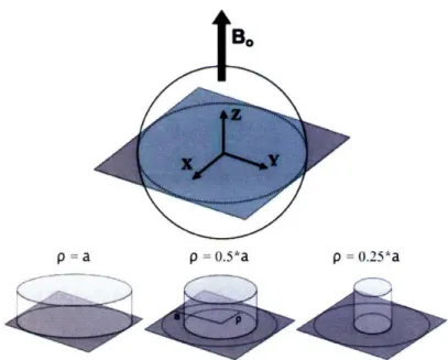
Ultimate intrinsic SNR was calculated inside a sphere with uniform electrical properties. The net EM field was derived by performing a mode expansion with dyadic Green's functions (DGF) (73), following a method recently described (74). We chose this approach over others relying on EM field-based sensitivity basis set (41,42), as the DGF formalism enables calculating the current patterns corresponding to the optimized SNR (74). Given any spatial current distribution J, the electric field can be calculated as:
E(r)=ico•uo G(r,r').J(r)d'r', (2.9)
sample
where po is the magnetic permeability in free-space and G(r, r ) is the branch of the DGF associated with the region indicated by r. We started by defining a complete basis set of surface current modes, distributed on a spherical surface at 5 mm distance from the surface of the modeled sphere. The generic surface current mode was expressed as:
K im =W(M, X,), (,p) W, X(E Xi, ,(9 ),
where 1, m are the expansion indices, Xi,m is a vector spherical harmonic and W,"M and Wf) are the series expansion coefficients representing divergence-free and curl-free surface current contributions, respectively. Dyadic Green's functions associated with a dielectric sphere were defined as double series of vector wave functions in spherical coordinates (74):
M1I, (r, k) = j, (kp)X,m (0, ()
(2.11)
Nim (r, k) = (1/k)V x j, (kp)Xl,m (9, (p)where k is the complex wave number, p is the radial coordinate and jl is a spherical Bessel function of order 1. Once the electric field is computed, the magnetic field can be derived as 0B(r) = (-1/ia)V x E(r).
We assumed that the hypothetical coils derived from the basis set were made of perfect conductors, to guarantee that only sample noise contributed to the ultimate intrinsic SNR. In this way, the denominator of Eq. (2.6) does not require any additional term and the encoding matrix and the noise covariance matrix in Eq. (2.7) and (2.8) can be constructed using Eq. [BS] and [B7] of Ref. (42), respectively. Eq. [B7] was
multiplied by the conductivity of the sample, to correct for a minor typographical error. The modeled sphere was chosen to match the geometry and the electrical properties of two existing spherical MR phantoms, henceforward referred to as "Phantom I and "Phantom 2 . Phantom I is a "Braino" phantom (GE Medical Systems, Milwaukee,
WI, USA) and Phantom 2 is a low-conductivity phantom (Siemens Healthcare, Erlangen, Germany). Both phantoms have diameter equal to 16.86 cm (Figure 2-1).
168
mm, 84 pixels
Figure 2-1. Schematic diagram of the image plane and the FOV used to calculate ultimate intrinsic SNR for the spherical phantom. The FOV is a square with a side of 16.8 cm, just large enough to contain the entire circular section. It is uniformly divided into an 84 x 84 grid of pixels.
Water solutions equivalent to the content of each phantom were mixed and their conductivity and permittivity at 123.22 MHz (the operating frequency of the MR scanner used in our experiments) were measured using an Agilent 85070E dielectric probe (Agilent Technologies, Palo Alto, CA, USA). Conductivity and relative permittivity were 0.97 Ohm- m-1 and 81.3 for Phantom 1, whereas for Phantom 2 they
were 0.084 Ohm- m-1
and 80. Magnetic permeability of free space was used in both cases. A transverse section through the center of the sphere was divided into an 84 by 84 grid of square pixels with 2 mm side (Figure 2-1) and ultimate intrinsic SNR was calculated at each position, assuming 2.89 T static magnetic field strength and room
temperature of 298 degrees Kelvin. Calculations were implemented in Matlab (MathWorks, Natick, MA, USA).
Experimental data acquisition
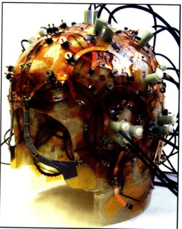
The spherical phantoms were scanned on a Siemens TIM Trio 3T scanner (Siemens Healthcare, Erlangen, Germany) using the same image planes modeled in the ultimate intrinsic SNR simulations (see Figure 2-1). The RF receive coil used in the SNR measurements was a receive-only head coil array (Figure 2-2) consisting of 32 overlapping circular surface coil elements arranged over the entire dome of the head (75), with the scanner body coil used for transmit. The coil was tuned and matched for a human head.
Figure 2-2. 32-element receiver coil array employed in the experimental study. The surface coils are packed on a thin helmet-shaped plastic frame that minimizes the distance from the sample.
A single proton density weighted two-dimensional gradient echo image was obtained with parameters TR = 2000 ms, TE = 3.8 ms, flip angle = 200, slice thickness = 3 mm, 128x128 matrix, FOV = 256 mm, pixel half-bandwidth = 25.6 kHz (line bandwidth = 200 Hz/pixel). A long TR was chosen to avoid any TI dependence in the image. To map the flip angle distribution over the phantom, eight additional images were acquired with identical pulse sequence parameter values but with increasing transmit voltages to achieve several nominal flip angles ranging from 600 to 1500 in 150 increments and receiving with the body coil, including a body coil noise reference acquired at 00 flip angle.
For each acquisition, raw k-space data were saved for offline analysis, and magnitude images reconstructed online were also saved for comparison. Each image acquisition was accompanied by a noise reference measurement obtained by recording complex-valued data with the array coil during the same pulse sequence used for the image acquisition but with no RF excitation; this ensured that the noise samples were bandwidth-matched with the image acquisition and that a sufficient number of noise samples were acquired to accurately estimate the noise.
Experimental SNR calculation
All image reconstruction and analysis was performed offline with custom software written in MATLAB (The Mathworks, Natick, MA). Image data were acquired with a Cartesian k-space sampling and two-dimensional Fourier imaging, thus a standard image reconstruction consisting of standard FFT operations for each individual coil channel was carried out. No apodization or filtering was applied at any stage of the
image reconstruction.
Due to the dielectric properties of the spherical phantoms, the flip angle of the RF excitation varied spatially over the phantom, with higher flip angles at the center of the phantom (76,77). Since the flip angle distribution affects image SNR, these transmit effects were identified and removed from the empirical SNR calculation. To compute the flip angle distribution, we fit a sinusoidal model of image intensity as a function of transmit voltage across the eight body coil reference images to each image pixel with
the MATLAB function "fminsearch". The fit produced two parameters at each pixel from which the achieved flip angle map @(x,y) was calculated. The flip angle correction map was then generated as sin ((x,y))/sin(89), where 60 is the desired flip angle (which in this case was 200, as specified above). This correction was applied to the individual coil images to normalize the effect of the intensity non-uniformity
caused by the flip angle distribution, giving rise to a compensatory intensity increase in the periphery of the phantom.
Because the phantoms contained no internal structure, the resulting image from a given coil element after flip angle normalization provided a good approximation to the element's sensitivity profile. Although noise contributes some degree of error to this approximation, no smoothing or interpolation was applied to the images to avoid introducing bias into the sensitivity approximation and subsequent SNR calculation. The noise covariance matrix IF was calculated from the statistics of the noise samples
scaled by dividing the sample covariance matrix I by the noise equivalent bandwidth b.o,, to account for noise correlations due to the filtering introduced by the data acquisition electronics and receiver, i.e. T = Y/boise, (78).
Images reconstructed for each coil channel from the fully sampled dataset were then combined with the optimal matched filter SNR combination method (14), which incorporates both the approximations of the coil sensitivity and the channel noise covariance matrices in the combination to boost the combined image SNR. Note that, because in the ultimate SNR simulations the signal is defined to be complex-valued, we adopt an observation model where the signal is assumed complex-valued and thus the image SNR calculated from the imaging data does not require an additional 4I
scaling (see, e.g., Ref. (78,79)). In order to eliminate any phase variation in the experimental data, the absolute magnitude of the final complex-valued combined SNR image was taken. A final correction was applied to the resulting thermal SNR images for the SNR bias introduced by the magnitude detection (78-80), which is the
generalization of the well-known Rician distribution correction (81) to multiple-channel coil arrays.
The optimal Roemer combination method yields the same SNR of a fully-sampled (i.e. unaccelerated) SENSE reconstruction (16). The resulting 128x128 SNR image was cropped around the object boundaries, resulting in an 84x84 image with each pixel corresponding to a position in the grid of computed ultimate intrinsic SNR values. SNR and g images for acceleration factors 2, 4, and 6 were obtained from the fully sampled dataset, using the SENSE reconstruction algorithm (16) with one-dimensional undersampling on the x-y plane. To maximize coil performance in the accelerated cases, the images were first cropped to produce a tight FOV around the phantom, resulting in a cropped image size of 84x84. Estimates of the coil sensitivity profiles were generated by low-pass filtering the resulting image intensities with a two-dimensional Hanning filter (normalized for unity noise gain) with a cutoff set to include only the central 25% of k-space. Noise covariance matrices were estimated as described above, and the geometry factor was calculated directly from the analytic expression (16).
Coil performance maps
The ultimate intrinsic SNR is calculated considering the effects of a net EM field acting at particular positions inside a sample, without associating them to actual MR image pixels. The values computed are therefore relative measures of the optimal SNR and, without losing generality in the discussion, they can be used to theoretically investigate the behavior of the optimum for various acceleration factors and at different field strength.
On the other hand, in order to compare the experimental SNR data with the simulated data, the ultimate intrinsic SNR values must be properly scaled to account for the
specific pulse sequence parameters and system characteristics:
V xe NacqNEX sin(0) SNR'(ro)ult intr = SNR(ro)ult intr vo xe F(2.12)
where Vvoxel is the volume of the voxel, Nacq is the number of the acquired k-space samples, which accounts for the signal summation resulting from Fourier transform, NEX is the number of signal averages, 0 is the nominal flip angle, F is the noise factor of the preamplifiers connected to the coils and Afis the receiver bandwidth. The noise figure (NF), which is the noise factor expressed in dB, was measured experimentally using the "hot-cold resistor" method (82) and the noise factor was then derived from
NF = 10 logl0 F . Table 1 summarizes the numerical values of the scaling factors, as
well as the values of the phantom's dielectric properties and of the other quantities used in the calculations. These quantities include the operating frequency o and the equilibrium magnetization Mo at the field strength of interest, here 2.89 T. Mo appears in Eq. (2.6) for ultimate intrinsic SNR, and must be accounted for correctly. The final value of Mo listed in Table 1 was computed using the expression:
Ny2hI (1 + 1) Bo
Mo = (2.13)
3kBT
with the gyromagnetic ratio y = 2.68x 10⁸ rad T- 1 s- 1, the temperature of the sample T
= 298 K, the main magnetic field Bo = 2.89 T, I = 1/2 for hydrogen and the number of nuclear spins per unit volume N= 6.691 x 10 28 m-3. kB is Boltzmann's constant and h is Planck's constant divided by 2)r. It is also important to notice that, although final matrix size is 128x 128, Nacq is equal to (256 x 128)/Racce ,, with Racce, being the
acceleration factor, because there were 256 k-space samples for each readout, due to an automatic 2-fold oversampling performed by the MR system.
An accurate scaling of ultimate intrinsic SNR is critical to the absolute significance of coil performance maps, which are defined as the ratio of the experimental SNR images to the corresponding scaled ultimate intrinsic SNR images:
SNR(ro)ay
CPM(r) = SNR() y (2.14)
Performance maps provide a measure of the efficiency of each coil array for the specific imaging task, as a function of position inside the sample of interest. Maps were generated for various acceleration factors.
Table 1
Dielectric properties, constants and scaling factors used in the calculations
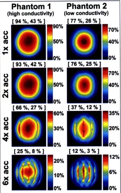
Coil performance maps for the 32-element head array are shown in Figure 2-3, for both phantoms and various degrees of acceleration. In all cases the performance, relative to the ultimate intrinsic SNR, was highest near the center of the object and approached zero near the surface, where the ultimate SNR assumes its largest values.
Larmor frequency co/2;r 123.22 MHz
Equilibrium magnetization Mo 9.03 x 10- A-m-1 Boltzmann constant kB 1.381 x 10⁻²³ J-Kl
Sample temperature T 298 K
0.97 Phantom 1 I
Conductivity c0.08 Phantom 2
81.3 Phantom 1
Relative permittivity e 81 Phantom I 80 Phantom 2
Vacuum permittivity so 8.85 x 10⁻¹² C2 -N1 m-2
Permeability 1P 1.2566 x 10⁻⁶ Wb-A-'-m'
Volume of the voxel Vvoxel 1.2 x 10⁻⁸ m3
Receiver bandwidth Af 51.2 kHz
Flip angle 0 0.3421 rad
Noise factor F 1.22
Signal averages NEX I
Acquired data points Nacq (256 x 128)/Raccel
Phantom
1
(high
conductivity)
f94
%. 43 %1
r 01 aoL A2 OL 1X
X
C4
X
X
ti(5
x
N
U
U
(5
x
U
U
$( r 25 oA. 8 % 1Phantom 2
(low conductivity)
r 77 oV_ 2A8 / 1 r-7Ro9 0 2oL 1 r 27 %. 12 %160%
30%
0%
20%
10%
0%
Figure 2-3. Coil performance maps for an axial slice at 2.89 T in the center of a uniform spherical phantom. The performance of the 32-element head array with respect to the ultimate SNR is shown for two different phantoms and various acceleration factors. Each pixel represents the experimental SNR divided by its corresponding ultimate SNR value. Above each map, the maximum and the mean performance are indicated in brackets and reported as a percentage of the optimum. The mean is computed including only the pixels inside the circular section of the object.
r RA oAh 27 o. 1I
35%
20%
0%
12%
6%
0%
[12%, 3% ]The peak performance was in the unaccelerated case and was 94% and 77% for Phantom I and Phantom 2, respectively. The maximum and mean performance (reported in square brackets above each map) both decreased as the acceleration factor was increased. For 2-fold acceleration the performance was almost equal to that in the fully-sampled reconstruction, whereas for 6-fold undersampling, noise amplifications substantially degraded image SNR and the maximum performance with Phantom I and 2 decreased to 25% and 12% of the ultimate SNR, respectively.
100"
(gultimate
/
garray)
[100 %, 98%]
[
89%,62%]
[66%,19%]
100%80%
60%
40% 20% 0%[100
%, 94 %]
[92
%, 52 %]
[76
%,16 %]
E0
oC
.= -, 80% 60%40%
20%
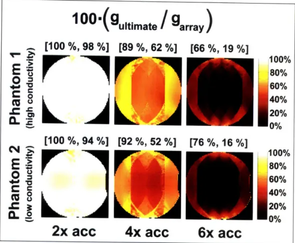
no/-Figure 2-4. Geometry factor performance for different parallel imaging accelerations at 2.89 T for an axial slice in the center of a uniform spherical phantom. The geometry factor of a
32-element head array with respect to the corresponding value in the ultimate intrinsic case is shown for two different phantoms and various acceleration factors.
2x acc
4x acc
6x acc
I
'T
'&lC
L
---100% .... V oFigure 2-4 shows the performance of the coil in terms of the geometry factor. Although these maps do not provide an absolute measure of the coil performance, they are useful in investigating the potentiality of the coil for parallel imaging tasks and they can be more easily calculated without worrying about the scaling factors in Eq. (2.12). We notice that the 32-element array is almost equivalent to a hypothetical infinite array for 2-fold acceleration, whereas its efficiency in accelerating by a factor of 6 is less than 20% compared to the ultimate case.
Phantom
1
Phantom 2
..
(high
conductivity)
(low conductivity)
0.8
00.6
'
0.4
S0.2
S2
4
acceleration factor
acceleration factor
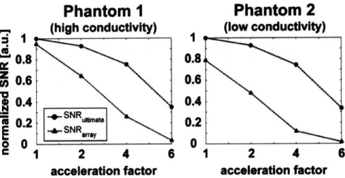
Figure 2-5. SNR as a function of acceleration factor for a voxel in the center of a spherical phantom. The SNR obtained with a 32-element head array is compared with the corresponding ultimate intrinsic SNR for two homogeneous phantoms, with equal dimensions and different electrical properties.
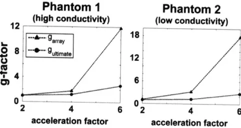
Comparisons with the ultimate intrinsic SNR and g in the center of the sample are shown as a function of acceleration factor in Figures 2-5 and 2-6, respectively. In Figure 2-5 we see that the performance of the coil is worse in the case of Phantom 2 and we also notice that, as we move to higher degrees of acceleration, the difference between the SNR of the coil and the ultimate intrinsic SNR increases more rapidly for Phantom 2. This is confirmed by the graphs in Figure 2-6, which show that for 2-fold acceleration ultimate intrinsic g and g of the array overlap for both phantoms, whereas for 6-fold acceleration g of the array becomes 12 for Phantom 1 and 18 for Phantom 2, though ultimate intrinsic g remains almost equal in both plots.
1