Publisher’s version / Version de l'éditeur:
Vous avez des questions? Nous pouvons vous aider. Pour communiquer directement avec un auteur, consultez la première page de la revue dans laquelle son article a été publié afin de trouver ses coordonnées. Si vous n’arrivez pas à les repérer, communiquez avec nous à [email protected].
Questions? Contact the NRC Publications Archive team at
[email protected]. If you wish to email the authors directly, please see the first page of the publication for their contact information.
https://publications-cnrc.canada.ca/fra/droits
L’accès à ce site Web et l’utilisation de son contenu sont assujettis aux conditions présentées dans le site LISEZ CES CONDITIONS ATTENTIVEMENT AVANT D’UTILISER CE SITE WEB.
Paper (National Research Council of Canada. Division of Building Research); no.
DBR-P-799, 1978-08
READ THESE TERMS AND CONDITIONS CAREFULLY BEFORE USING THIS WEBSITE. https://nrc-publications.canada.ca/eng/copyright
NRC Publications Archive Record / Notice des Archives des publications du CNRC : https://nrc-publications.canada.ca/eng/view/object/?id=a2196d23-fe5c-4dcd-8a03-0e4861be8e77 https://publications-cnrc.canada.ca/fra/voir/objet/?id=a2196d23-fe5c-4dcd-8a03-0e4861be8e77
NRC Publications Archive
Archives des publications du CNRC
This publication could be one of several versions: author’s original, accepted manuscript or the publisher’s version. / La version de cette publication peut être l’une des suivantes : la version prépublication de l’auteur, la version acceptée du manuscrit ou la version de l’éditeur.
For the publisher’s version, please access the DOI link below./ Pour consulter la version de l’éditeur, utilisez le lien DOI ci-dessous.
https://doi.org/10.4224/40001769
Access and use of this website and the material on it are subject to the Terms and Conditions set forth at
A method of achieving positive pressure in a fire resistance furnace
McGuire, J. H.
NATIONAL RESEARCH COUNCIL OF CANADA COUNSEIL NATIONAL DE RECHERCHES DU CANADA
A Method of Achieving
Positive Pressure in a
Fire Resistance
-,.
Furnace
b y J . H . McGuire
Reprinted from FIRE TECHNOLOGY
y
p
.
11. No. p. 195-205 3, August 1978DBR Paper No. 799 Division of Building Research
SOMMAIRE
On peut cre'er une pression positive
i
n'importe quel niveau dans une chaudikre en situant la sortie du conduit de fum6e au- dessous plut6t qu'au-dessus de ce niveau et en limitant le diam6tre de la sortie du conduit. I1 est souvedqsauhaitable .-
,
d'assurer un debit d'air continu aux brf leuq. ~ i v e r s facteurs
,
de s6curit6 jouent un r61e tres important. aFIRE TECHNOLOGY
A
Method of Achieving Positive
--Pressure in a Fire Resistance Furnace
J. H.
McGUIREFire Research Section, Division of Building Research National Research Council of Canada
Positive pressure may be developed at any level in a furnace by
locating the flue outlet below instead of above that level and by restricting the area of the flue outlet. Maintaining a constant air supply to the burners is often desirable. Various safety factors are of great importance.
D
URING the first half of this century the pressure differential be- tween the interior and exterior of a test furnace was not generally regarded as a critical factor governing the fire resistance of a test specimen. Other than the suggestion that furnace pressures should approximate ambient, pressure specifications were not included in fire resistance test standards, and if anything, i t was customary to design furnaces to op- erate a t negative pressures to avoid pollution of the laboratory by furnace gases.More recently in North America positive pressure has been shown to be of considerable significance in determining the fire resistance of par- titions penetrated by plastic drain, waste, and vent pipe.' With the interest currently being shown in the use of such pipe as a replacement for metal drain, waste, and vent pipe, a need arises for test furnaces ca- pable of positive operation.
Elsewhere in the world, the significance of positive pressure has received greater recognition, having developed in the context, for example, of test- ing wooden doors and floors. Certain IS0 and IMCO standards specify that tests shall be carried out a t positive pressures of the order of 10 Pa (0.04 in. WG), a minimal value that can be achieved without much so- phistication.
R E Q U I R E D T E S T P R E S S U R E D I F F E R E N T I A L C A P A B I L I T Y
The pressure differential capability required of a fire resistance test furnace is dependent principally on the levels of pressure differential 195
Copyright 01978, NATIONAL FIRE PROTECTION ASSOCIATION, 470 ATLANTIC AVE., BOSTON, MASS. 02210
~
196 Fire Technology Ilikely to be encountered during fires in buildings. A secondary factor is the expected nature of the dependence of fire performance on magnitude of pressure differential. For many classical constructions involving mini- mal leakage, there will be no such dependence. The work previously referred to,' however, shows that, for plastic pipe penetrations, influence increases as pressure rises to 12 Pa (0.05 in. WG) but does not show great further variation up to the limit investigated, 124 Pa (0.5 in. WG). The pressure differentials to be expected across a partition during the course of a fire are not primarily generated by the fire itself, although in a fairly tight enclosure the growth period can give rise to values of 25 Pa (0.1 in. WG). Other mechanisms, principally building heating stack action and wind, will generate the pressure head and the effect of the fire will be to destroy exterior windows. The pressure differential previ- ously appearing across the exterior walls will then develop across the interior walls, floor, and ceiling bounding the fire compartment. Ex- terior walls are usually about twice as tight as interior walls, hence the pressure difference across an exterior wall (with windows intact) is likely to be four times the value across adjacent interior partitions. .
A wind velocity of about 6 m s-I (13 mph) corresponds to a pressure head of 25 Pa (0.1 in. WG) and a velocity of 25 m s (56 mph) to a head of 400 Pa (1.6 in. WG). Although these values show that wind derived pressures can sometimes be of considerable significance, building heating stack effect constitutes the most troublesome source of adverse pressure differentials in Canadian buildings of any substantial height.
The total stack effect that can be generated by the heating of the interior atmosphere of a building is equal to the difference in weight of the lightweight column of gas within the building and the more dense column of colder gas (of the same height) outside the building. I t is thus given by
where h = building height,
g = acceleration due to gravity, p , = exterior air density,
p = interior air density,
T o
= absolute exterior temperature, andO = difference, interior and exterior temperatures.
For a 10-m (33-ft) high building, a total stack effect of about 25 Pa (0.1 in.
WG)
can be generated with a temperature difference of 50" C (90" F), and multiplying by ten, a high building (100 m; 330 ft) can thus generate 250 Pa (1 in. WG). In general, the leakage in a building will be fairly symmetrical, and air will flow into the lower half of the building and out the upper half. The maximum pressure differential that could appear across a partition (following window breakage) will, therefore, usually be less than half these values.Positive Pressure 197
I t follows that furnace pressure differential capability should definitely
exceed 12 Pa (0.05 in.
WG)
and might well attain 124 Pa (0.5 in. WG),although restricting furnace leakage sufficiently to achieve such a value might prove difficult.
T H E O R E T I C A L M E A N S O F A C H I E V I N G P O S I T I V E P R E S S U R E
In designing a furnace to operate a t a positive pressure, it is con-
venient to take advantage of two mechanisms - stack action and the
customary pressure drop across an opening as gases flow through it. Stack effect has been discussed in the previous section in the context of building heating, and the following expression for the total available head was derived:
6p = hg p e 0/To
This form of the expression was convenient because the conditions con- sidered involved a constant value of p,, the interior temperature being maintained constant (by building heating) and the exterior temperature T o being the variable. In the context of furnace design, it is the density of the exterior atmosphere (the laboratory) that is constant, the density of the interior atmosphere being highly variable. The expression can then be written as
6p = hgpo 0/To
where h = height of heated column under consideration,
g = acceleration due to gravity,
p
,
= laboratory air density,T = absolute interior gas temperature, and
0 = difference, interior and laboratory temperatures.
The values of g and p , in this expression being constant, the only in-
dependent variables are
h
and 0/T @ or 0, because T o is a unique functionof 0. Figure 1 shows the pressure head generated per unit height as a
function of temperature difference 0. In the absence of a temperature
difference, no stack effect exists; then initially (as 13
<<
To) it increases substantially linearly. At higher temperatures, it rounds off, tending toa limiting value as %/To tends to unity.
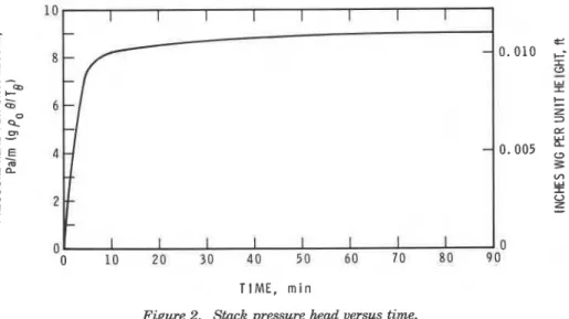
Figure 2 shows the pressure head that is generated by stack action
in a furnace following the standard time-temperature curve. After 10 min, it shows remarkably little variation. The failure to develop substan- tial positive pressure in the first few minutes of test is not of much im- portance, for during that period the furnace gases have not attained temperatures that will make their flow through cracks and fissures of great significance.
Figure 3 illustrates an idealized floor test furnace in which the flue outlet is a t a lower level than the location a t which positive pressure is desired. The value of the differential attained will be proportional
198 Fire Technology
T E M P E R A T U R E D I F F E R E N C E , " C
Figure 1 . Pressure head per unit height of flue.
to the dimension "h" in the figure. Where the specimen itself has a sig- nificant height, when a wall is being tested, for example, the pressure differential across the wall will vary with height. Over a 3-m (9.84-ft)
height, the variation might be 25 Pa (0.1 in. WG), an amount probably
of the same order as the design value of differential to be established a t the chosen height.
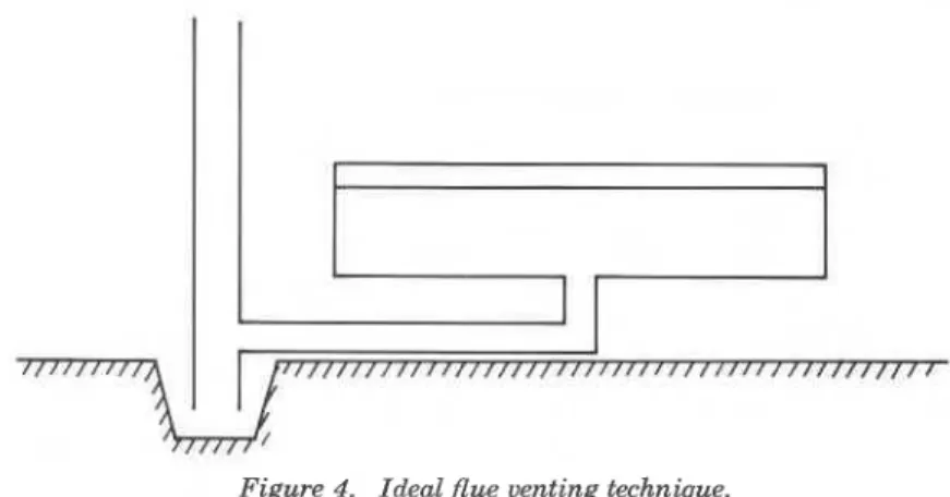
Exception might be taken to terminating the flue a t a low level as il- lustrated in Figure 3. Should a chimney be demanded, it must be vented a t the bottom to ensure that the flue outlet is a t atmospheric pressure and not the negative pressure that would be induced by the chimney. Figure 4 illustrates an arrangement that will ensure that miscellaneous effects, such as wind induced pressures, will not cause outflow from the vent. Under adverse conditions, a body of hot gases would build down the chim- ney beneath the level of the (furnace) flue outlet, thus generating positive pressure a t the outlet and ensuring an upward flow.
The second technique of developing a positive pressure differential in
a furnace is to ensure that gases (air) are injected into the furnace a t an
appropriate rate and to install a restriction in the flue outlet. A pressure
differential then appears across the restriction following Bernoulli's classic ,
law:
6p = p u 2 / 2
i
where u is the velocity of the gases, and p is the density.
Positive Pressure 199
10 I I I 1 I 1 I I
1
TIME, m i n
Figure 2. Stack pressure head versus time.
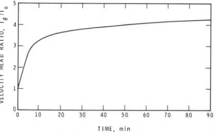
reduced by a factor (the orifice factor) probably having a value of 0.6. Both the density and the velocity of the gases will be functions of tem- perature, and thus the above pressure differential (or velocity head) will increase during the course of the test. Figure 5 illustrates the tempera- ture dependency, which is linear, and Figure 6 illustrates the resulting time dependency in a furnace following the standard fire resistance curve. In the various furnaces having positive pressure capability that have been built a t the National Research Council of Canada (NRCC), the two mechanisms (stack action and orifice pressure differential) have been about equally significant in achieving the objective of positive pressure. The (flue outlet) orifice-generated pressure differential can conveniently serve as a means of controlling furnace pressure by installing a damper in the flue system. The rate of gas and air injection into the furnace must then always be suflicient to permit control. I t is also desirable that total gas and air flow be substantially constant to minimize necessary modula- tion of the flue damper.
These requirements were satisfied in the NRCC furnaces by modulating the gas supply only, with variation of heat input requirement, and by supplying air through the burner ports at all times at a constant rate ap-
,TEST S P E C I M E N
F U R N A C E F L U E O U T L E T
I { / / ! / / / / I / / # / / ~ ~ ~ I / / I / / { / / I C I C I C I C ~ ~ ~ / / ~ / ~ ~ ~ ~ / / / / / ~
200 Fire Technology
t
I
Figure 4. Ideal flue venting technique.
propriate to the maximum heat requirement. Flows have proved ade- quate to permit control of the pressure differential according to these principles. Fuel gas flows remain modulated and hence vary the total gaseous flow into the furnace, but because the absolute maximum fuel (propane) flow is only 1/25 the air flow, modulation does not result in substantial pressure variation. The effect of variable heat input, hence variable gas temperatures and densities, has a greater influence on ori- fice-generated pressure diffbrential than does this mass flow variation.
In three of the NRCC furnaces designed for positive pressure opera- tion, the flue dampers are controlled manually, and in one a reversible, low-speed electric motor is used.
S A F E T Y A N D M I S C E L L A N E O U S D E S I G N C O N S I D E R A T I O N S
Having chosen to maintain a constant air supply to the burners, we are able to make an appreciable capital saving by eliminating venturi mixers. The approach adopted in the NRCC furnaces has been to re- gard the air supply system virtually as a plenum and to reduce pipe diameters slightly a t each burner port to constitute a restriction pro- ducing the appropriate pressure difference. Provided all the final branches are similar, the resulting distribution of air to the burners is uniform. In the main supply lines, a flow velocity of about 20 m s-I (66 fps) is adopted, giving a velocity head of 240 Pa (1 in. WG). In each final branch, the velocity head is about doubled by raising the velocity almost 50 percent (achieved by a 15 to 20 percent reduction in pipe diameter). The only ,
airflow control valve for the main burners is the inlet vane damper pre- ceding the main blower.
Gas is injected into the air line supplying each burner some distance (" 300 mm, 1 ft) before the burner to permit adequate mixing. A control cock is available at every burner - a facility that is not offered for air
Positive Pressure 201
T E M P E R A T U R E R I S E , " C Figure 5 . Velocity head versus temperature.
vision of individual control valves for all supplies to each burner is not wise. The illusory advantage of flexibility is more than offset by oper- ator problems in setting up the burners.
Following that principle, the 4 MW (14 million Btu h-l) NRCC floor furnace has on1 y one air line valve and one gas line valve to control fifteen
pilot burners. A meter is located after each of these valves, bearing state-
ments of the acceptable ranges of readings. The main gas supply to each burner is thus the only variable for which operator judgment is re- quired.
With this particular design of furnace the most untoward possible event
is probably an air supply failure. A first essential is, therefore, to ensure
that the power supply for all gas solenoids is derived from the power supply for the blower motor. Having thus guarded against blower failure
from loss of power supply, the much less likely event of some other form
of blower failure must be taken into account. In two of the NRCC posi-
tive pressure furnaces, protection is ~rovided by a simple airflow switch
based on a counterweighted vane. In a third furnace, a proprietary air pressure switch has been used and duplicated to ensure reliability.
202 Fire Technology
TIME, m i n
Figure 6. Velocity head ratio versus time.
When a safety feature is not automatically in the fail-safe category, it is important that appropriate (and suitably labelled) indicator lights should exist. Thus, in the case of the air pressure switches referred to, the furnace operators have become familiar with a particular sequence of events. On switching on the blower, a red "airflow failure" lamp is illu- minakd for about 2s until the blower has attained some speed when the
green ' ' a ~ o w OK" light appears. I t is to be hoped that any change in
this sequence would be noticed and reported.
Flame-failure sensing is not invoked when the pilot gas solenoid and ignition circuits are switched on, because failure to ignite is not regarded as presenting undue hazard. Airflow to the main burners will have been established, and thus the pilot gas, even if not ignited, will not be able
to create a furnace atmosphere approaching the flammability limits.
I t is after pilot circuits have been established (and preferably a visual check of the pilot flames made) that the flame-failure circuits are powered. If these register the presence of adequate pilots, gas may then be sup- plied to the main burners.
When a furnace test has been completed, it has been ruled that the main gas supply line should be bled to substantially atmospheric pres- sure (from a gauge pressure of about 200 kPa; 29 psi). The flame-failure unit will not permit the completion of this process, and a push-button flame-failure overriding circuit has been included. One contact of the relay involved is utilized to electrically latch it. When any furnace circuit is switched off (as will immediately follow the bleeding of the gas line), the overriding circuit drops out and does not reenergize. Such a circuit calls for prominent and adequately labelled indicator lights.
A
gas explosion constitutes such an extreme hazard that, even afterPositive Pressure 203
to include explosion reliefs. The necessity for this measure is discussed in a later section. In the design, rather than considering sophisticated theory, it is convenient to use the simple rule of thumb3 of incorporating
1 ft2 of relief for every 30 ft3 of volume (1 m2 for every 9 m3).
F L A M M A B I L I T Y L I M I T P R O B L E M
The technique of modulating only the gas supply to the main burners, and not the air, has given rise to a side effect that occurs when the large floor furnace is used for stress relieving certain metal components. This procedure involves a slow rise in furnace temperature up to a value of about 600" C, and the effect is produced during the later stages of the operation. A blue flame progresses across the furnace, taking about 2s,
and the cycle is repeated a t intervals of about 1 min. The phenomenon
generates a gauge pressure of approximately 1 Pa (0.004 in.
WG).
I t has been inferred that the mechanism responsible for the phe- nomenon is the dependence of flammability limits on gas temperature. When the gas supply rate to the main burners gives a gas/air mixture below the flammability limits, it does not ignite despite the presence of
a vigorous pilot flame. After a brief residence time in the furnace and a
consequent rise in temperature, the mixture comes within the now ex-
panded flammability limits, and a flame is briefly sustained.
A
purgingperiod then ensues, during which the products of the limited combustion that has taken place are discharged to the flue and a new flammable mixture builds up.
From the dimensions of the furnace and the fan characteristics, the time constant for the delivery of one volume of air proves to be approxi- mately a minute, which is consistent with the cycle time of the event.
During normal use of the furnace, the event cannot occur because the incoming mixture never falls below the "cool" value of the lower flam- mability limit during the period in which the furnace is passing through the critical temperature range. At higher temperatures, combustion beyond the burners would be a continuous and not a cyclic process and would not be sensed (without highly sophisticated equipment).
If desired, the phenomenon could be effectively avoided by modifying the gas flow modulating technique. One approach might be to cut off the gas supply entirely to two-thirds of the burners upon reduction of the flow rate to a very low level. A gas concentration below the lower flammability limit a t ambient temperature would then be diluted by a further factor of three on entering the furnace. The cycling phenomenon might in fact still persist, but its magnitude would be so reduced as to make it virtually undetectable.
C O M B U S T I B L E S P E C I M E N S
It
is often taken as a rule of thumb by combustion engineers that204 Fire Technology
vided the optimum amount of fuel is added to an air supply, the heat
output of a burner is virtually independent of the nature of the fuel. With the design of furnace here described, it therefore follows that com- bustion of the pyrolysis products from a combustible specimen could gen- erate heat a t the maximum rate for which the furnace was designed. This feature is also found in several other North American fire resistance furnaces where combustion is effected by diffusion flames and control of the air sup- ply is generally associated with stack action or a stack fan not being de- pendent on the rate of fuel supply. When testing wooden doors, for example, laboratories have found that such furnaces give higher tempera-
tures than those specified in the test standard during the early stages of
a test. Since the furnaces have been modified a t NRCC, there has been no call for such large-scale tests. Tests involving combustibles in the small furnaces have necessitated substantial reductions in fuel supply but have not given rise to temperature overshoot.
The testing of combustible specimens should also be considered in the context of the need for explosion reliefs, mentioned previously. Almost regardless of the furnace heating principles adopted, a fertile imagination can conceive of products of pyrolysis coming within the flammable limits while temperatures are below ignition values. I t is conceivable that a substantial proportion of the furnace volume might develop an explosive atmosphere. Provision of explosion relief is therefore desirable. Provision of one or two premixed pilot flames a t strategic locations near the speci- men might also be helpful.
C O N C L U S I O N
The principle of controlling furnace pressure by the use of a flue damper and minimizing the necessary consequent adjustment by not modulating the airflow to the burners has been adopted in the design of four NRCC
furnaces - the two small-scale and the large-scale wall and floor furnaces.
The only undesirable feature that has been encountered has been the cyclic deflagration phenomenon, but this has not proved to be of suf- ficient importance to warrant the corrective measure outlined.
Specimens with a substantial exposed combustible content have been tested in the small-scale furnaces and have not given rise to temperature overshoot. The experience of other laboratories operating with constant air supply (but a t negative pressures) suggests, however, that this may occur during the operation of the larger furnaces.
Temperature control during normal operation of the furnaces has proved superior to that prevailing with previous burner arrangements, because the cooling rate with the burners shut off is more nearly com- parable to the heating rate with the burners operating a t maximum ca- pacity.
I t will be apparent that the technique is not economical in the use of fuel. Flue gas losses normally constitute a t least a third of the total
Positive Pressure 205
heat losses, and the adoption of a constant air flow will raise this pro- portion, the inefficiency arising when the heat input requirement and consequently the fuel supply are reduced. However, the fuel cost of a typi- cal test is less than $100, which is a small fraction of the total cost.
R E F E R E N C E S
McGuire, J. H., "Penetration of Fire Partitions by Plastic DWV Pipe," Fire
Technology, Vol. 9, No. 1 (February 1973), pp. 5-14.
Tamura, G. T., "Computer Analysis of Smoke Movement in Tall Buildings,"
ASHRAE Transactions, Vol. 75, Part 2 (1969). pp. 81-92.
Fire Protection Handbook (13th edition, - ~ a t i o n a l Fire Protection Association,
Boston. 1969). ,, w.
-
17-61.North American Combustion Handbook, (North American Manufacturing Co.,
Ohio, 1952), p. 16.
NOTE: This paper is a contribution from the Division of Building Research, Na- tional Research Council of Canada, and is published with the approval of the Di- rector of the Division.