Publisher’s version / Version de l'éditeur:
Vous avez des questions? Nous pouvons vous aider. Pour communiquer directement avec un auteur, consultez la
première page de la revue dans laquelle son article a été publié afin de trouver ses coordonnées. Si vous n’arrivez pas à les repérer, communiquez avec nous à PublicationsArchive-ArchivesPublications@nrc-cnrc.gc.ca.
Questions? Contact the NRC Publications Archive team at
PublicationsArchive-ArchivesPublications@nrc-cnrc.gc.ca. If you wish to email the authors directly, please see the first page of the publication for their contact information.
https://publications-cnrc.canada.ca/fra/droits
L’accès à ce site Web et l’utilisation de son contenu sont assujettis aux conditions présentées dans le site LISEZ CES CONDITIONS ATTENTIVEMENT AVANT D’UTILISER CE SITE WEB.
Research Paper (National Research Council of Canada. Division of Building
Research); no. DBR-RP-153, 1962-04
READ THESE TERMS AND CONDITIONS CAREFULLY BEFORE USING THIS WEBSITE. https://nrc-publications.canada.ca/eng/copyright
NRC Publications Archive Record / Notice des Archives des publications du CNRC :
https://nrc-publications.canada.ca/eng/view/object/?id=856c2048-6eac-4e24-80b1-9a6a798c5008
https://publications-cnrc.canada.ca/fra/voir/objet/?id=856c2048-6eac-4e24-80b1-9a6a798c5008
NRC Publications Archive
Archives des publications du CNRC
This publication could be one of several versions: author’s original, accepted manuscript or the publisher’s version. / La version de cette publication peut être l’une des suivantes : la version prépublication de l’auteur, la version acceptée du manuscrit ou la version de l’éditeur.
For the publisher’s version, please access the DOI link below./ Pour consulter la version de l’éditeur, utilisez le lien DOI ci-dessous.
https://doi.org/10.4224/40001465
Access and use of this website and the material on it are subject to the Terms and Conditions set forth at
A treatise on theoretical fire endurance rating
Ser
TH1
N21r
2
no.
153
c.2
ANALYZED
NATIONAL
RESEARCH
COUNCILC A N A D A
DIVISION OF BUILDING RESEARCH
A TREATISE ON THEORETICAL FIRE ENDURANCE RATING
BY
T. Z. HARMATHY
REPRINTED FROM
AMERICAN SOCIETY FOR T E S T I N G MATERIALS. SPECIAL T E C H N I C A L PUBLICATION N O . 301. 1961. P. 10
-
4 0RESEARCH PAPER NO. 153
O F THE
DIVISION OF BUILDING RESEARCH
OTTAWA APRIL 1962
T h i s publication i s being d i s t r i b u t e d by the D i v i s i o n of Building R e s e a r c h of the National R e s e a r c h Council. It should not b e r e p r o d u c e d in whole o r in p a r t , without p e r m i s - s i o n of t h e o r i g i n a l p u b l i s h e r . T h e D i v i s i o n would be g l a d to be of a s s i s t a n c e i n obtaining s u c h p e r m i s s i o n .
P u b l i c a t i o n s of the Division of Building R e s e a r c h m a y be obtained by m a i l i n g the a p p r o p r i a t e r e m i t t a n c e , ( a B a n k , E x p r e s s , o r P o s t Office M a n e y O r d e r o r a cheque m a d e p a y - able a t p a r in Ottawa, to the R e c e i v e r G e n e r a l of C a n a d a , c r e d i t National R e s e a r c h Council) t o t h e National R e s e a r c h Council, Ottawa. S t a m 2 s a r e not a c c e p t a b l e .
A coupon s y s t e m h a s been i n t r o d u c e d to m a k e p a y - m e n t s f o r publications r e l a t i v e l y s i m p l e . C ~ u p o n s a r e a v a i l - able i n d e n o m i n a t i o n s of 5 , 2 5 and 50 c e n t s , and m a y b e ob- tained by m a k i n g a r e m i t t a n c e a s i n d i c a t e d above. T h e s e coupons m a y b e used f o r the p u r c h a s e of a l l National R e s e a r c h Council pltblications including s p e c i f i c a t i o n s of the Canadian G o v e r n m e n t S p e c i f i c a t i o n s B o a r d .
Autl~orized Rcprint from tllc Copyriglitcd Symposium on Pirc Test Lletliods
S p e c i a l T e c l r ~ s i c a l P~rblicaliorc :Yo. 301
Published by the
:I>~EI<ICAS SOCIETY FOR TESTIXG BI.\TERI~\LS
A N . ~ L Y Z E D
1961A T R E A T I S E O K T H E O R E T I C A L F I R E E N D U R A N C E R A T I N G BY T. Z. H.-IRM.&THY~
For most building materials, the enthalpy-temperature relationship is not linear but contains steep sections a t places where latent heat is absorbed as a result of desorption of moisture, dehydration, dissociation, or transformation. Partly associated with these physicochemical changes, and partly independent of them, the thermal conductivity also undergoes considerable variation. These are the main reasons why the usual assumptions are not valid when the heat flow through building elements during fire exposure is to be calculated.
A numerical method is described which can be used successfully for solving one-dimensional transient heat flow problems of any complexity. The applica- tion of this method to the calculation of temperature history of building elements during fire exposure is illustrated through some examples. I n cases where the building element is not subject to thermal disintegration or collapse the numerical heat flow analysis will yield the fire endurance of the building element. I n other cases the heat flow analysis must be coupled with a numer- ical stress-deformation analysis.
T h e theoretical side of fire endurance rating has long attracted considerable interest. During the past two decades a number of interesting contributions have been published but, unfortunately, the "prediction" of fire test results was the only concern of speculation. D u e to the lack of adequate knowledge on the be- havior of building materials a t high temperatures, many important aspects of the real heat transfer mechanism were disregarded.
T h e problem of predicting fire test re- sults has been approached in three dif- ferent ways. T h e first approach was t h e empirical one. I n 1942 the National Bureau of Staildards recommeilded a
formula whose general form was as follows (1) :2
The formulas3 developed recently b y Clarke (2) a n d Keisel (3) a r e also of this type. T h e uilsoundness of a n y formula of the above form will be pointed out later in this paper.
A different approach was taken b y those who attempted to derive methods of prediction by solving the Fourier equation of heat conduction. Some work on this line was done by t h e Brandveil- igheidsinstituut in Holland (4). A method of calculating the fire endurance of
1 iVationa1 Itesearch Council, Fire Section, Division of Building Research, Ottawa. Ontario, Canada.
The boldface i~nml>crs in parelltheses refer to the list of rcfcl.cl~ccs al>pentlccl t o this ~)apcr. See list of synlbols al,l)ended +.o the gagcr.
10
!lomogeneous walls or floors under cer- tain idealized conditions has been pre- pared b y the author (5).
The third approach, the adaptation of the electrical analog method for the prediction of fire endurance, was first de- scribed b y Lawson and McGuire (6). T h e method was originally developed b y Beuken (7) and was later improved b) Robertson and Gross (8). Further gen- eral improvements were suggested b y F a t t (9). \ , With these methods certain
problems connected with heat flow through composite slabs can also be solved.
Whether the method of reference (5)
is used for the prediction of fire test re- sults, or any of the above analog meth- ods, the calculations cannot be accom- plished without a radical simplification of the problem. While assumptions such as the constancy of thermal conductivity and certain heat transfer coefficients and the linear relation between the enthalpy and temperature are sometimes allowable for certain materials (generally metallic or ceramic) and within moderate tem- perature ranges, they are not allowable for the large majority of building ina- terials and under conditions prevailing during a fire exposure.
PROPERTIES OF BUILDING MATERIALS AT HIGH TEMPERATURES
When dealing with heat flow through materials that are liable to undergo cer- tain physicochemical changes as a result of heating, it is very convenient t o in- troduce a new material property defined b y the following equation:
which may be called "volumetric enthalpy."
Although rigorously a set of calo- rimetric, thermogravimetric and dilato- metric measurements are necessary for determining the
H
versus T relationship,it can often be estimated with fair ac- curacy from thermodynamic data re- ported in the literature, for example Chemical Engineers' Handbook (lo), and the results of differeiltial thermal- and thermo-gravimetric analyses, as will be discussed in a subsequent publication (11).
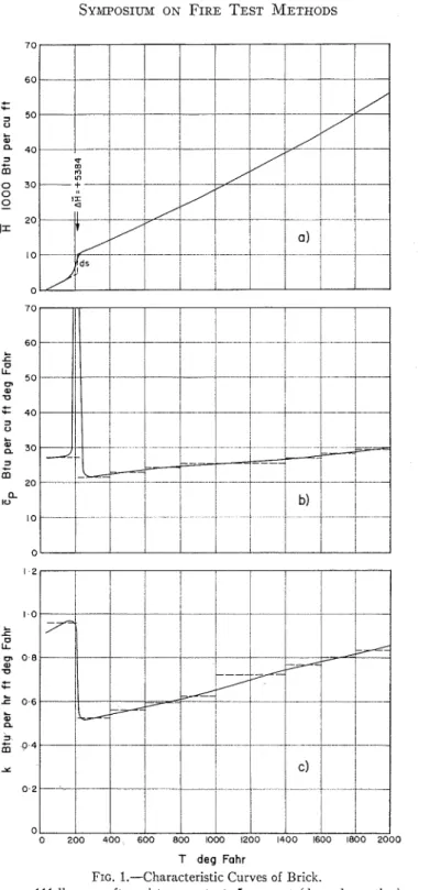
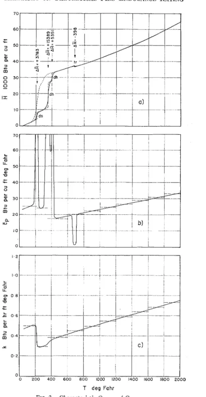
Figures l(a) and 2(a) show the
R
versus T relation for two building ma- terials. T h e first may be called "brick," the second "gypsum." Although it is convenient t o attribute the whole course of these curves to some single material, rigorously this is almost always incor- rect. I n the case of gypsum, for example, the material in the 32 to 150 F interval is C a S 0 4 . 2 H 2 0 which contains 5 per cent moisture adsorbed to t h e surface of the pores. Around 212 F, first the mois- ture leaves the pores (desorption), then, a t somewhat higher temperatures the CaS04.2H20 itself becomes unstable, and, in two steps, the H 2 0 molecules separate from the crystal lattice (de- hydration). At about 680 I.' the soluble anhydrous CaSOd transforms into a n in- soluble modification which is stable u p to 2240 F where a small amount of CaS04 dissociates into C a O and SOJ
.
Finally, a t 2520 F the melting of the C a G C a S 0 4 eutectic mixture takes place (12,13). Since physicocliemicalchanges like these are always accom- panied b y absorption or evolution of latent heats, the temperature intervals in which t h e changes take place can easily be recognized from t h e inflections (or breaks) of the versus T curve.
The
H
versus T curves shown in Figs. l(a) and 2(a) are those obtainable during the heating of materials. It should be emphasized that they are not "equi- librium curves," since the enthalpy a t certain temperatures does n o t necessarily belong to the compound or modification which is the most stable a t t h a t tempera- ture. (The experimental determinationT deg Fahr
FIG. 1.-Characteristic Curves of Brick.
T deg Fohr
FIG. 2.-Characteristic Curves of Gypsum.
p = 78 lb per cu ft, moisture content: five per cent (ds = desorption, dh = dehydration, tr =
of the "equilibrium curve" is not always possible.) The non-equilibrium nature of the
B
versus T curves is reflected in that their shape may depend very strongly on the rate of heating. I n the case of gypsum, for example, at low rates of heating (say, a t 10 F per min) the de- hydration begins at much lower tem- peratures and theH
versus T curve drawn in dotted line results.The full-line curve of Fig. 2(a) has been based on information available from the literature (12,13,14). Excepting its high-temperature portion, the curve is probably fairly accurate, although there is some doubt about the actual tempera- tures of dehydration under conditions generally met during fire exposure. The curve of "brick" (Fig. l(a)) has been estimated from data reported for fire clay bricks (15). The accuracy of the plot is not known, but it is certainly good enough to serve to illustrate the fire en- durance rating procedure and to yield at least approximately correct conclusions. I n order to fit to the nature of the numerical procedure, the
a
versus T curves must be "idealized." The "ideal- ization" is based on the following two principles: (a) the curves are composed of straight-line portions, (b) sensible and latent heats are not absorbed simul- taneously. This latter principle implies that all physicochemical changes occur a t definite temperatures so that during the changes the enthalpy varies along verti- cal lines, as shown in dashed lines in Figs. l(a) and 2(a). The length of these vertical sections (the volumetric latent heat of the changes) are also given in the figures.The gradient to the
H
versus T curves can be recognized as being the heat capacity :By substituting the expression of
H
fromECI 1 and considering that (dp/dT)p is geilerally a small quantity, one obtains
I n Figs. l(b) and 2(b) the
cp
versus Tcurves of "brick" and "gypsum," re- spectively, are also plotted. I t is seen that E p may assume very high values over temperature intervals in which physicocl~emical changes take place. These values are obviously due to the absorption of latent heats associated with the changes and clisappear if one employs the second principle of "ideal- ization" according to which sensible and latent heats are not absorbed simul- taneously. Thus the "idealized" Zp versus
T curves do not contain outstanding singular points. Owing to the lirst prin- ciple of "idealization," however, the "idealized" Cp versus T curves are not continuous but are composed of a num- ber of Zp = constant sections (see the dashed line plots of Figs. l(b) and 2(b)). At the places of discontinuity, Ep should be taken as the mean of the values in tlle previous and subsequent intervals.
Knowledge of the thermal conduc- tivity of the materials is, of course, also needed for any heat flow analysis. The k versus T relation for the above two materials is plotted in Figs. l(c) and 2(c). Although these curves have been based on rather meager informatioil (10,15), their accuracy is probably satisfactory.
The figures show that these materials, like porous materials in general, exhibit fairly high thermal conductivities in the range 32 to 212 F , due to the presence of adsorbed moisture. Although the way in which moisture can influence the heat transmission is very complicated and still not fully understood, there are available data such as those from the work of Cammerer (16) which express the effect in terms of thermal conductivities for various levels of moisture content. The result of his observations has been
utilized when plotting the low-tempera- where: ture portion of k versus T curves.
~h~ "idealized" k versus T correla- A
*
= 0.1 1 for two vertical surfaces, and tions are shown in dashed lines in the A* = 0.16 for two horizontal surfaces, figures. They consist of a number of k = the hotter surface facing upwards.constant sections. At the places of dis-
continuity one can take again the mean In both cases
of the values in the previous and subse- T I
+
TII quent intervals. T , = ---2 " ' ' . (6)
HEAT TRANSFER BY CONVECTION The above values of -~l* are somewhat AND RADIATIOX lower than the ex~erimental values At the surfaces of the solid consti-
tuents of building elements the heat is transferred by a combined natural con- vection radiation mechanism. The laws of these mechanisms are fairly well es- tablished. The generalized form of the equation concerning the heat transfer by natural convection between a flat solid surface and the air is as follows (10,17) :
where:
A = 0.27 for a vertical surface, and
A = 0.38 for a hot horizontal surface facing upwards (and probably also for a cold horizontal surface facing downwards).
The fact that if T,
>>
T, 11, is propor-tional to the
5
rather than the4
power of (T, - T,) (18) will be disregarded here, because a t larger values of (T, -T,) the heat transfer by natural convec- tion is only of secondary importance.
By means of E q 4, the coefficient of convective heat transfer between two surfaces through an air layer can also be determined. If the heat absorbed by this layer is neglected on the basis of heat balance calculations, equations can b e developed whose general form is:
found by Griffiths anh Davis (17).
The coefficients of radiant heat trans- fer can be derived from the Stefan-Boltz- mann law. I n the case of radiant heat transfer from a surface to non-reflecting surroundings,
If heat is transferred between two par- allel surfaces (whose distance is small compared with their size) through an air layer which is again assumed to be a
non-absorbing medium,
In the temperature interval concerned, E(= EI = €11) = 0.91 can be taken as a
good average for the most common non- metallic surfaces.
The coefficient of heat transfer by a combined convection radiation mech- anism is the sum of the coefficients for the two individual mechanisms,
I1 = I!,
+
h,. . . . ( 9 )or,
II* = 11:
+
IL: . . . (10)the coefficients of heat transfer for all cases commonly met in lire endurance rating can be calculated. In Fig. 3, lz, and hh are plotted (in full line) against T, for T, = 74 F (the yearly average
temperature of the furnace laboratory of the National Research Council) and for E = 0.91. By taking
75
F for the origin plots of the lz, versus T and lz,, versusF ,
functions are obtained which are rela- tively insensitive to the value of T,
,
therefore they can be used without re- striction for calculating the heat loss from the unexposed surface of wall or floor4 and 5 are graphical representatiolls of the lz: = I Z ~ ( T ~
,
TI,), and lz: = IL;(T,,
TI,) functions, respectively, for E , =EII = 0.91. These charts can conveniently be used for computing the heat flow be- tween two parallel non-metallic surfaces within a wall or floor during fireesposure. I t is interesting to note that Iz,* and h z appear to be iildependeilt of the distance between the surfaces. The experiments of Griffiths and Davis (17), and Schmidt (19)
showed that this is true, supposing the sep- aration of the surfaces is larger than about
4 in. (For smaller separations the convec-
constructions, respectively, during fire exposure.
I t was originally thought that in the furnace laboratory of the National Re- search Council the heat loss from wall constructions might be somewhat re- duced by the presence of some reflecting surfaces; therefore all fire endurance calculatioils have been carried out with an apparent value of 0.85 for E in Eq 7.
This value now seems to be a bit on the low side, but such small variations in the value of E have hardly any effect on the
result. The R, versus T curve for E =
0.85 and its ('idealized" form as well, are also shown in Fig. 3.
The families of curves shown in Figs.
tive heat transfer decreases considerably with decrease in the thickness of the air layer.) Thisisinsharp contrast to Clarke's belief that the fire endurance of a building element increases with the increase of the width of a n ellclosed continuous air gap (2).
The method to be discussed here is essentially the same as that described b y Dusinberre (20,21), but propounded in a more general form to make it suitable for solving the rather complex problems of fire endurance rating.
The first step is, as is common in nu- merical analyses, to select a finite num-
ber of points of the solid a t which the variation of temperature will be ex- amined. The distance between these points must be sufficiently small to justify the conception that the conditions (temperature and material properties) a t each point are regarded as representative not only of the point itself, but of a cer- tain region which includes the point. If
the heat flow is one-dimensional, this region is obviously a slab perpendicular to
the direction of heat flow.
In the case of a homogeneous solid the logical choice is to locate the reference points at equal Ax distances; thus inside the solid they are in the midplane of ele- mentary slabs of Ax thickness, as shown in the sketches of Table I.
For the ith point inside the solid the following heat balance can be written
heat entering the heat leaving the
=
(eley;arry)
- (e1e;e2;;y)sensible heat latent heat
=
(
absorbed b y)
+(
absorbed by)
the elementary the elementary slab in At time slab in At time
where:
k(i-I)
+
kik+l)i =
-
etc.. . . . .(I21 2I n E q 11, the heat absorbed by the ith elementary slab during the jAt
<
t<
( j+
1)At period is calculated on the basis of conditions (temperatures, thermal con- ductivities and heat capacities) prevailing in the (i - l)th, ith and (i+
1)th slabs at the beginning of the period. Conse- quently At must besmall enough to justify this procedure.By rearranging Eq 11 one finds that:
T;i+l) + (i+l)X. ~ i i - 1 ) ;
1
-
T{L1)ci
where :
At
K(i-l)i = k(i-l)i - etc.. . . . . . ( l 4 )
Ax and by virtue of Eq 12: K(i-1,
+
Ki K(i-11i = 2 etc.. . . . .(IS) where: At Ki = ki - etc. Ax Further: Ci = (Gp)i A x . . . (17) andEq 13 yields the temperature a t the ith reference point a t t = ( j
+
1) At time, T$'+'), in terms of T:;-,), Tz , and Tti+'),
the temperatures at the (i - l)th, ith, and(i
+
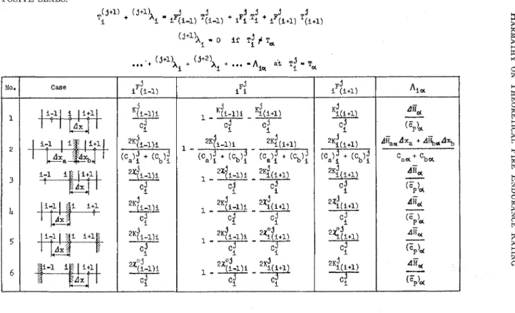
1)th points a t t = jAt, and can be applied to any point inside a homogeneous solid. At the boundaries of homogeneous regions the surface or inter- face temperatures are generally of inter- est; therefore the reference points should be located on the surface or interface, as shown in some of the sketches of TableI. In addition. a t the interface of two homogeneous solids it is usually neces- sary to change the distance between t h e reference points. For all the various cases that one may meet while dealing with
TABLE I.-l~ORI\IULAS F O R CALCULATING T I I E T R A N S I E N T T E M P E R A T U R E S I N S I M P L E O R COhI- POSITE SLABS.
(3+1) + (j+l)X , j j j j j .I
Ti i iF(i-1) T(i-l) + iFi Ti + iF(i+l) T(i+l)
(j+l)A
-
0 if T!+
,T . . : + (j+l)x i + (j+2!, +...
=Aier
at :T = T N r NO. case i-11
i1
i+11-
( F F ) ~ dk,dxa + A%*A% C a ~ + 'ba - *Ha-
( FP)& diid-
GPb,
A&-
( : p ) d A&-
(Fp)H 1 T - - ( - I c : j 2 (ca)! + icb): (c.): + (cb): 3 5 11-1I
a i i+lEE
c,? "1, dad iF(i-1) j-
Ki(i+l)
cJ j 2Ki(i+1) ( ' a ) : + (cb); 24i+l) C : '$3 2'4(i+1)4
iFi ~ji-l)i ~?(i+l) i ~j (i+l) jone-dimensional heat flow problems, absorbed). Thus instead of T?+" the equations have been developed (by writ- temperature equivalent of the absorbed ing the heat balance for an ith point) latent heat, (jf1)X; should be calculated: which all have the following general (i+l)h. - .F' T'
form : % - % (i-1) (i-1)
The iF{
,
and i ~ { ~ + ~ , "tempera- ture coefficients," corresponding to the various cases, are listed in Table I. I n all casesThe equations defining X{;-l);,
x;(ifl) ,
xT:-l)
,
andxT;i+l)
are as follows:x(i-l)i = l~(i-~);At etc.. . . (21) X;i-l), = /~r,-~),at etc.. . . . (22) where:
h( ,-1)
,
etc. = II,, or hl,,
and*
*
hTi-l)i
,
etc. = lz,, or lz,,and can be calculated by means of Eqs
4 to 10 or can be determined by the use of the graphs in Figs. 3, 4, or 5.
According to the "idealized" enthalpy- temperature correlations, the heat ab- sorbed by an ith elementary slab is either sensible heat or latent heat. The two kinds of heat, under "idealized" condi- tions, cannot be absorbed simultaneously (though may be absorbed within the same A1 time interval, one after the other). Equation 19 is therefore a com- bination of two equations. I n such tem- perature intervals where only sensible heat is absorbed, (i+l)X, = 0, and E q
19 reduces to:
On the other hand a t T i = T, also
T','+" = T, (since sensible heat is not
The various steps involved in a numeri- cal heat flow analysis are as follows:
1. Locate the reference points, that is, choose the value of Ax (or in the case of composite slabs choose the values of Axn AX,, ' .').
2. By means of Table I find the ap- propriate formulas for T;j+", T;'+",
.
- .
~ ' j + l '
.
(Points 1 a n d n are located in the surrounding medium, and the variation ofT!'+"
and T?+') is prescribed among the boundary conditions of the problem.)3. Choose a convenient value for At. (This choice is not entirely free; a cer- tain "stability criterion" should be satis- fied, as will be discussed later.)
4. Calculate A,, As,
. . .
(A,,,
h a p ,' ' ' Abp
,
Abs,
' ' ' n a b ,,
n a b S I ' ' ' Aubp,
Aeu,.
-
.) from the known values of AH,, A H , ,. . .
(AIL,,AH^, , . .
.
&bp, ~ 1 2 ~ ~
,
.
.
.) by means of the for- mulas given in Table I.5 . Prepare graphs of the "idealized" K versus T(& versus T, Kb versus T,
.
.), C versus T (C, versus T, Cb versus T,. .
-), and, supposing the temperature of the surroundings is constant, of the "idealized"x
versus T functions over the appropriate intervals. These graphs are based on the available k versus T (k, versus T, kb versus T,. .
.), c p versus T ( E ~ , versus T, E P ~ versus T, a ) ,and h, or h,, versus T correlations, and on Eqs 16, 17 and 21.
6. Starting from the initial Ty
,
Ti,
. .
.
T$,-1),
TyL values (prescribed for1 = 0) the values
xis ,
K &,
K$,,
. .
* o
i - i -
,
x i -
i j Kg(i+l),
. .
GT,-2)(n-l) 9 x?,r-l)n
,
ci
,
Ci,
'.
C?n-l)are first to be found, then by means of the above established (9% -
$
equationsTABLE 11.-EXALIPLE 1 : CALCULATION OF F I R E ENDURANCE O F A BRICIC WALL OF 39.4 IN. TI-IICI<NESS CONT.4INING 5 P E R C E N T blOISTURE ( R E F E R R E D T O OVEN DRY WEIGHT). p = 110 L B P E R CU P T , c p = 0.216 BTU P E R LB D E G F A H R , k = 0.55
T:
,
T i ,. .
~ t , - ~ )
,
that is, the tempera- ture distribution in the slab a t t = At,are to be calculated. Since Ti and
TX
are known from the boundary conditions, a complete set of the T1 to T, temperatures is again available, on the basis of whichd-2
,
K:3, ~ ~.
. .
4 ~:,,--2)(~-i) ,,
x?,,-I),,,
C?' , Ci
, .
Ctn-l),
and subsequently T5 , T:,
. .
T:,,-~) (the temperature dis- tribution at t = 2At) are to be computed.7.
Carry on the computation using Eq 19a until Ti1+" first exceeds T, (a temperature a t which heat is absorbed). Take T?+"-
T, = (j+"Xi and use Eq19b for calculating subsequent values of Xi ((i+?)Xi
, (j+3)Xi
,
. . .
) UntilThen take
and continue computing T(j+"+'), T('+~+",
.
+ + by means of Eq 19a.If a t T, heat is evolved, upon reaching T, add Ai, to Ti'+') and continue cal- culating T(jf",
. . .
by means of Eq 19a.If the temperature of the surroundings is not constant or if air gaps are included in the slab, Iz or h* (respectively) depend on two variable temperatures (T, and T,
,
or TI and TII); thus the values ofx
or x* cannot be pre-plotted. This makes the calculations somewhat more labori- ous.If the properties of a homogeneous solid are independent of the temperature, that is, if for any value of j K(i-l)i =
Ki(i+l) =
. .
-
= K, and Ci = C(i+s =.
. .
= C, it is convenient to choose Ax and At in such a way as to make R/C =8.
In this case for points inside the solidequivalent of absorbed latent heat) of the ith point a t t = ( j
+
1) At is obtained as the average of the temperatures of the(i
-
l)th, ith and (i+
1)th points a t t = jAt.A detailed description of the technique to be used in cases when the properties of the materials are not functions of the temperature (with the possible exception of k) is found in Dusinberre's publica- tions (20,21).
I n order to eliminate any major error from the calculations a so-called "sta- bility criterion" must be satisfied. The "stability" of an equation means that errors existing in the solutions at t = jAt will not increase but will be "smoothed out" during subsequent calculations. I t can be shown (22) that the criterion of stability is that
or, in words, i ~must be a positive value. i Before starting the calculations one must ascertain that with the selected values of Ax and At inequality 23 will be fulfilled, even at the point where the most adverse conditions are expected to be met. I n cases, however, when some heat transfer coefficient varies rapidly with the temperature, it may not be prac- tical to choose At so as to satisfy the in- equality 23 throughout the whole period of interest. I n order to reduce the labor it is wise to adjust At, from time to time, as the heat transfer coefficient varies.
The accuracy of this numerical pro- cedure is demonstrated in the following example. At t = 0 moment the tempera-
ture of one face of an 8-in. thick wall is suddenly increased from 74 F to 1810 F. The other surface continues to be in con- tact with air at 74 F. The physical prop- erties of the wall are as follows: p = 110
TI,-,,
+
Td+
T;i+l) lb per cu ft, c p = 0.216 Btu per lb deg Tki+" + (i+l'X. -I -
3 Fahr, k = 0.55 Btu per hr f t deg Fahr
(one may call this material "brick"). +hat is, the temperature (or temperature The heat transfer coefficient at the hot
surface hl -+ m, a t the cool surface
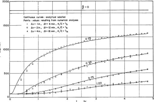
h = 2.82 Btu per hr sq ft deg Fahr. The analytical solution of this problem is available (5) and is shown in solid lines in Fig. 6. The points represent values re- sulting from numerical analyses. I t is seen that even with very rough length and time steps (Ax = 4 in., At = 18 min) the points are located reasonably close to the theoretical curves.
marks the end of the period of "thermal" fire endurance. I t would be most unwise, however, to adopt indiscriminately all the rules of the experimental test procedure, inother words, to think that the purpose of the theory is merely to "predict" the result of fire endurance tests. The requirement that the temperature under asbestos pads must be regarded as the unexposed sur- face temperature is definitely one of those
FIG. 6.-Comparison of Analytical ancl Numerical Solutions.
CALCULATION OF FIRE ENDURANCE The practical measure of the fire en- during quality of a construction is the "fire resistance," the time for which the construction functions as a fire barrier in a specified sense, when subjected to a standard fire endurance test. I t is wise to define the theoretical measure of that quality in an analogous way, for example, to adopt the definition of the "standard fire exposure" in the same way as it is given in ASTM Method E 119 (23) or to
agree on the principle that a certain rise of temperature a t the unexposed surface
which can be ignored without conflicting with the logic.
The calculatioil of temperature history of the construction must always be the first step of any theoretical fire endurance rating procedure, even if certain rise of temperature at the unexposed surface does not constitute a criterion for failure. In cases where the construction is not subject to thermal disintegration or col- lapse, the temperature history of the un- exposed surface only is of interest, so that the heat flow analysis is equivalent to the calculation of fire endurance. In
other cases the heat flolir analysis must be coupled with a numerical stress-de- formation analysis the technique of which is described elsewhere (24).
Since the coefficient of heat transfer a t the surface exposed to fire is extremely high, observance of the "stability cri- terion" would result in very inconvenient values for Ax and At. Calculations show however, that no serious error is intro- duced by taking the temperature of the surface exposed to fire to be that defined as the "furnace temperature" in ASTM Method E 119 (23).
The desorption of moisture and the accompanying phenomena are always very important parts of the heat flow mechanism during fire exposure. As Figs. 1 and 2 show, the desorption generally takes place a t temperatures in the vicinity of the boiling point of water. What exactly happens to the desorbed vapors afterwards is not fully under- stood. If they leave toward the hot sur- face, they will absorb sensible heat and hinder the heat flow through the con- struction. If, on the other hand, they move in the direction of the cool sur- face, a inajor part of the vapors will con- dense in a neighboring layer and gradu- ally fill up the pores with free water. Under the effect of high pressure gradi- ents, the free water sclueezes toward the unexposed surface, especially along some cracks, where the resistance to liquid flow is the lowest. This combined vapor- liquid flo~v mechanism obviously aids the heat flow through the construction.
I t is possible that the effect of migra- tion of water toward the cold surface is already taken into account to some ex- tent by the use of the higher thermal con- ductivity values in the 32 to 212 I; in- terval. Any attempt to treat the problem of migration of moisture in both licluicl and vapor forills in a rigorous manner would lead to serious complications. Fortunately, observations during fire
endurance tests performed in an electric furnace indicated that there is significant vapor movement both toward and away from the hot surface; therefore it is not entirely unreasonable to assume that no serious error is coillmitted if the migra- tion of desorbed vapors is disregarded. Since this assumption is obviously one of some importance to the results, an ex- tensive future investigation would be justified.
Similar problems may be met in con- nection with dehydrations occurring a t relatively low temperatures (for exam- ple, the dehyclration of gypsum). In the case of dehydrations taking place a t higher temperatures (for example, some dehydrations of set portland cement) the released vapor quantity is generally small and conde~lsation
is^
seldom ~ossible: therefore the heat transferred by the vapor flow is rarely significant.Although the u
a
versus T curve of brick is probably not so smooth as that shown in Fig. l ( a ) , differential thermal analyses revealed that in the 250 to 2000 F range no significant physicochenlical changes can be expected. I t seems, there- fore, that in the case of brick construc- tions the assumption of the constancy of the thermal diffusivity, k / c p,
may be permissible provided it is not the fire endurance itself which is sought but the effec~ of some variables (other than k andCp) on the fire endurance.
The following three problems have been studiecl on this assumption:
1. The variation of the fire endurance of brick walls with moisture content,
2. The effectiveness of air gaps as heat flow barriers,
3. The dependence of the fire endur- ance of asymmetrical constructioils on the direction of heat flow.
I11 all of these analyses, p = 110 lb per cu ft, c p = 0.216 Btu per lb deg Fahr, and k = 0.55 Btu per 11r ft cleg Fahr have
been chosen as values representative of red clay brick. The heat transfer coeffi- cient a t the unexposed surface is left as variable and its values are to be taken from the "idealized" h, (for E = 0.85) versus T , plot shown in Fig. 3.
From the above three groups, two analyses will be reproduced in this paper, as examples for the application of the numerical procedure.
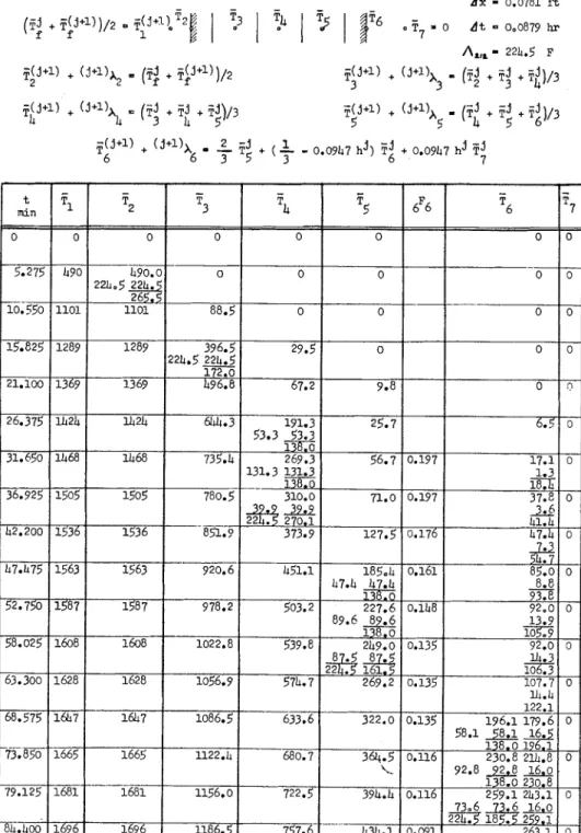
In the first example the fire endurance of a 3:-in. thick brick wall of 5 per cent
where the numerical procedure is illus- trated. I t has been thought that the con- dition of "standard fire exposure" is better approsimated by using (T;
+
Tjj+l')/2 instead ofTjJ+"
for the nomi- nal temperature of the combustion prod- ucts.If the heat of clesorption (per unit weight of moisture) is considered ap- proximately equal to the heat of vapori- zation of water (AH = 970 Btu per lb), the temperature equivalent of the latent
moisture content (referred to oven clry heat of desorption of 5 per cent moisture weight) is calculated. The locatioll of the is obtained as
reference points is shown in Table 11.
The value of At that makes li/C =
5
A = 0.05 X 970 = 224.5 Fcan be coinputed by means of the equa- 0.216
tion
1 c
(az)?
At = - E ! L L
3 k
which has been obtained by combining Eqs 3, 16, and 17. With An: = 0.07813 ft one gets At = 0.0879 hr (5.275 mill).
The equations to be used in the anal- ysis have been deteriniiled by nleans of Table I. They are listed in Table 11,
by virtue of the expression for in Ta- ble I, and Ecls 1 and 3. Under "icle- alized" collclitions the desorption is as- suined to take place a t 212 F, that is, at = 138.
The stability of the calculatioils is satisfied if 0.333 - 0.0947 l ~ j (= ,F:) is a positive value for
T,
5
250I:
(up to the point of thermal failure). The masi- mum value of tl in the concerned intervalHARMATHY ON THEORETICAL FIRE ENDURAXCE R A T I N G 5 m m d
d.8823
0; N h 2 4 2 2 g N N v, z g m g g.
.
.g
"-
W C...
N Nm mm md
d
L
d
3
d G w g Z 0 u\ m m m m m...
. .
...,
...?
r( d I2
N w2
d I N r l ma
22JZ8qSZ
3::42
s
w m m mz
s.d~~~
2
C N 0...:
3
e
"2 ;f F-$
K m F- ON<
~
3
4
.
.
.
P
E
:
:
r
;
~
.
.
;
?
f w o m w m o r- < ~ Q w . < ~ ( ~ ~ ? N . ~ - ~ ~ N ~ ~ w F - ~ ~ ~ - ~ ~ o c ~ o ~ . + o N w , - I N o N ' O d m "d
t N - * - X $ X ~- . . . d i 8 . . . i d . . . $ g $ $ .
2s2
P E m m m ogi,%$zF-m
r&d@gs~
- d ~ 0 0 0 0 0 < 9 9 3 d m 1 u\ m m N~ ~ $ & $ ~ . . . ~
m,: ": u\ 0.2
m m m * : : 4 9 9 ? ? 5 Y S 0 - ? " ' O J N rl d-.;
3
-3 494g ~ g 5 w g 2 ~ $ p ~ 2
w 4 4 m 5 4 ' 0 4 9 w ? ? ~ m2
.
...g N.
No mI? w a < < d d d d i m9
d d o ' d3
X a X 0$
d m w w t -da
* *...
d2
M
2 Q rl m N0
0
Ns
N;
2"
21
3 ,of
T,
is 2.825 Btu per hr sq ft deg Fahr Table 111. The numerical procedure is (see Fig. 3); thus ,F;2
$0.066. also shown there. When computing When determining the temperature a tT'i'"
andT';'",
the routine calculations point 2 it must be remembered that this must be interrupted in order to find point actually represents a layer of 0.469 ha by means of Fig. 4.in. thickness. Although this layer is as- Table I11 shows that a t points 6 and
7
sumed to absorb sensible heat at an in- the stability criterion cannot be satisfied finite rate, when latent heat is absorbed with the above given values of Ax and its temperature is lagging behind the At longer than 1 hr 40.225 min. At this temperature a t point 1. point a smaller K/C must be chosen. The calculations indicate that the Since K/C is proportional to Al/(Ax)?, "thermal" fire endurance of the wall is 1 the most effective way of reducing K/C hr 23 min. A number of similar calcula- is by doubling Ax (whenever this choice tions have been performed for various is possible). In this way K/C =
A,
values of the moisture content and the and the equations listed on the right- wall thickness. The result of these calcu- hand side of Table I11 will result. I t is lations is summarized in Fig. 7. The seen that with K/C = the stability knowledge of the relation between mois-
-
criterion is satisfied throughout the rest-
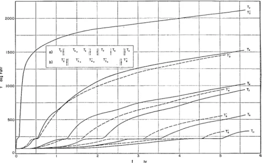
ture content and increase in fire en- of the calculations.durance will enable the testing authorities The variation of the temperature a t to correct the fire test resilts in such cases different ~ o i n t s of the wall is shown in where specimens of relatively high mois- Fig. 8. For comparison, the curves relat- ture content have to be tested. ing to the first case (when the two layers In the second group of analyses the fire of brick are in good contact) are also endurance obtainable by the use of two shown (4). One can observe that the gain brick layers of 3;-in. thickness and 5 per in the fire endurance resulting from the cent moisture content has been investi- insertion of an air gap is only 12.5 per gated. Two calculations have been Der- cent. Since the coefficient of heat trans-
-
formed, one for the 'case when the two fer through an air layer is practically layers are in good contact and the second independent of the thickness of the layer, for the case when they are separated b y this gain cannot be increased by increas- an air gap of 1 in. thickness. The analysis ing the distance between the two brick of the second case is partially reproduced layers.
in this paper. In the third group of analyses, two Figure 4 shows that at the beginning
of fire exposure the coefficient of heat transfer through a vertical air gap is about 1 Btu per hr sq ft deg Fahr. Since it is impossible to foresee how high h,* will rise during the esposure, the best way to start the calculations is to choose again Ax = 0.07813 ft and At = 0.0879 hr with which l i / C = and the stability
criterion is satisfied at any point, a t
calculations have been performed in order to point out the effect of the sequence of various layers on the fire endurance. The formula introduced by the National Bureau of Standards (1) and rediscovered by Clarke (2) and Neisel (3) indicates that there is a widespread misconception about this point. Their formula (repro- duced in the introduction) suggests that the fire endurailce of a construction is least for some time after the beginning -
of the fire exposure. The equations, which " Some uncxl)cct,ccl inflections of t,l~e curves are similar to those of the ex- are clue to certain a s s u n i l ~ t i o ~ ~ s 011 1~11ich this nu~ncrical nlc?thocl is hasccl. "Smoothing" thc. ample, are listed on the left-hand side of curves is tl~crcfore justifictl.
independent of the arrangement of the various layers. To prove the falseness of this concept, two analyses have been carried out. The fire endurance of a 4-in. wall composed of two layers of two dif- ferent kinds of brick has been calculated in both directions. The properties of "brick a" were considered the same as those used in the previous examples, while "brick b" was supposed to be of the
chemical stability are better utilized on that side of the wall on ~ v l ~ i c h fire is more likely to happen.
I n the case of chemically unstable ma- terials this rule may not be valid, as will be seen from the result of the following analyses in which the effect of gypsum plaster on the fire endurance of brick walls has been investigated. Since the properties of gypsum are strongly de-
t hr
FIG. 8.-Temperature History of Brick Walls of Five Per Cent Moisture Content.
( a ) Wall with air gap, and (b) Wall without air gap.
same density and specific heat, but of twice as high thermal conductivity. T h e moisture content was assumed to vary between 3 per cent (at the surfaces) and 5 per cent (in the midplane).
The first analysis related to the case when the layer of "brick b" was on the side exposed to fire and yielded a fire endurance of 58.5 min. The second anal- ysis showed, on the other hand, that the same wall was of 18 per cent higher fire endurance when the opposite side was subjected to fire. I t follows that layers of low thermal conductivity and high
pendent on the temperature, in these calculations no simplifying assumptions could be used. The properties of "brick" and "gypsum" were considered to vary according to the "idealized"
cp
versus Tand k versus T curves shown in Figs. 1
and 2.
The following three cases have been analyzed: (a) 3%-in. brick wall with no plaster on either side; (b) 3%-in. brick mall wit11 %-in. gypsum plaster on the side to be exposed to fire; and ( 6 ) 3%-in. brick wall with %-in. gypsum plaster on the side opposite to the fire.
T.\BI,E IT'.-EX.\lIPLE 3: CALCULATIOS O F ICIRE ENDURAKCE OF 3% IN. CLAY BRICK W.iLL, COVERED II'ITH 35 I N T H I C K GYP- SUM PLASTISR ON T l I E S I D E E:Xl'OSF>D TO 1211<E. PEIYSIC'.\L PKOPERTIICS OP AI.4TEltI.4LS ARE GIVEN I N FIGS 1 AND 2.
Calculations concerning the fire en- durance in case (b) are partially repro- duced in Table IV. As usual, first the ref- erence points are located and the equa- tions for calculating the temperature a t these points are established. The third step is to choose A( in such a way as to satisfy the stability criterion. (Because of the small value of Ax, the largest allow- able value of At is determined by the 3173
2
0 requirement.) Then the tempera- ture equivalents of the latent heats a t the various reference points are com- puted, and finally the "idealized" plots of I<, versus 7 ,-
C, versus p , I < b versus p , Cb versus T, andx
versus p are prepared, as described in the previous section (these plots are shown in Fig. 9).The analysis proper starts a t this point. The calculation of
p?
,
p 3 , and is shown in detail in Table IV. I t may be useful to pick a temperature from the table, saypi
= 156.6, and describe how it has been obtained. The equation writ- ten for point 3 shows that for calculatingpi
one must know the value of (I<, a tTz
= 785.9), I<:, (K, a tpi
=108.2), Kg3 (I(1, a t
F:
= 108.2), I<:.$ (Kba t
pi
= 16.1), (Cn a t pi = 108.2), and Ci3 (Cb a tpi
= 108.2). By means ofFig. 9(a) one will find that K:? = 0.660!
K::, = 0.668, thus (according to Eq 15)
I<:,, = (0.660
+
0.668)/2 = 0.664.Sinlilarly, by means of Fig. 9(c), Ki:, =
K i l = 0.683; therefore Ki34 = 0.683, as
~vell. Finally, from Fig. 9(b) C& = 1.053, and from Fig. 9(d) Cia = 2.134. By sub- stituting these values into the equation of point 3, one gets
+
"A:, = 351.3. At = 138, however, latent heat is ab-sorbed \vllose equivalent temperature is
A, = 194.7 (calculated according to the formula given in Table I for the inter- face of two solids). Since 351.3
-
194.7 =156.6
>
138 (the temperature a t which the desorption talres place), all latent heat is absorbed in one step, that is 4 ~ 3 = l i 3.
The fire endurance of the wall has been found to be 1 hr 36 min. The analysis of case (c), on the other hand, yielded 1 hr 45 min. This result is contrary to the es- pectation, because the material of lower thermal conductivity (gypsum) proved less effective on the side exposed to fire. I t seems, therefore, that the thermal con- ductivity is not the only factor which determines the best location of a layer in a construction.
The fire endurance in case (a) (un- plastered brick wall of 3% in. in thick- ness) is 1 hr 10 min. This would increase to 1 hr 29 min by the addition of a %-in. brick layer. These results prove the ef- fectiveness of gypsum plaster as a heat flow barrier on either side of a wall. This is principally due to its high heat absorp- tion during the dehydration process.
Recently an attempt has been made to apply the above described numerical technique to combustible constructions, namely, plank walls. With the assump- tion that the elementary slabs disappear as soon as the temperature a t their cooler side reaches 525 F (the lower limit of the beginning of exothermic reaction), plausi- ble fire endurance values have been ob- tained.
In the case of steel supported con- structions the temperature history of the steel parts is of primary interest. On the basis of this information the progress of deflection and the point of collapse can be calculated. Once the heat flow analysis is completed, the temperature history a t any point of the construction, thus a t points in the steel parts, is, of course, available.
I n the Fire Research Laboratory of the Division 01 Building Research about 30 numerical analyses have so far been per- formed with the aim of obtaining infor- mation on the fire endurance of construc- tions of various materials (brick, gyp- sum, concrete, wood). I t was found that simpler problems, like Example 1 (Ta-
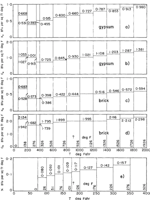
1.0 0 u C & u 3 . 5 a a 3 + m G o : T deg Fahr U. 0 a 0 2.0 C +
::
L " a - 0 3 .- m T deg FahrFIG. 9.-Auxiliary "Idealized" Graphs for Example 4.
ble 11) can be solved in a few hours. T h e ties for performing accumulative multi- solution of more complicated problems, plication is recommended. Programmiilg like the one shown in Example 3 (Table the fire endurance problems for digital
IV), may require several days. The use of computers does not seem very practical some electric desk calculator with facili- at this time.
0683,
0528 0 200 400 600 800 1000 1200 1400 1600 1800 2000 0.422 2.134 1.942 ; o O " N " "rb.373
(1.682 0-444 , O D w w w 1 1.899 w (U t- 1.795 1.739 t - N N 0.398 0.386 0.516brick
- T w N m 0.546 0.572c)
0'594_ 1.995 deg F w 'U - 2.116I
brick
2.212d )
Nr-
w (U !!2 2.298 w N E w C\1 LOThis ~lulnerical procedure can easily be ACKKO~LEDGMENT
extended to the analysis of two dimen-
sional heat flow problems. X discussion The author wishes to thank J. L. Bis-
on this subject is beyond the scope of son who performed a major part of the this work. calculations.
a = constant of various dimensions
A,A" = constants, Btu per hr sq ft F5'"
6 = constant of various diniensions c = specific heat, B t u per Ib deg Fahr
E = heat capacity, Btu per cu ft deg Fahr
C = "capacity number", Btu per sq f t deg Fahr
IZ = "temperature coellicient", dimension- less
11 = coeficient of heat transfer, Btu per h r sq ft deg Fahr
II = enthalpy, Btu per lb
B
= volumetric enthalpy, Btu per cu ft AB = volumetric latent heat, Btu per cu ft j = 1 , 2 , 3 ,...
k = thermal conductivity, Btu per h r ft deg Fahr
K = "conductivity number", Btu per sq ft deg Fahr
1 = thickness of a homogeneous slab, thick- ness of a layer in a con~posite slab, ft
L = latent heat absorbed or evolved by a unit volume of the solid, Btu per cu ft
tt = number of reference points, dimen- sionless
s = number of layers of solids in a com- posite slab, dimensionless
t = time, h r At = time step, hr
T = temperature, deg Fahr
= T
-
T , , temperature above the level of ambient air (in this paper T , = 74 F ) , deg FahrT, , To
,
. . . T ,,
T c,
. .
. temperatures a t which latent heat is absorbed or evolved, deg Fahrr = distance from the fire exposed surface, f t
Ax = distance between reference points, ft Greek Letters:
7 = constant, dimensionless
e = emissivity of surface, dimensionless
h = temperature equivalent of the latent heat absorbed or evolved by unit vol- ume of the solid, deg Fahr
A = temperature equivalent of latent heat,
deg Fahr
p = density, Ib per cu ft
a = Stefan-Boltzmann constant, 0.173 X
loF8 Btu per hr sq ft R4
T = time of fire endurance, h r
x = "transfer number", B t u per sq ft deg Fahr
Subscripts:
a = of the air
a , b,
...
= relating Lo material "a", material "b", etc.ah = relating to the interface of materials "a" and "b"
c = by natural convection
f = of the "furnace" (according to ASTM
E 119)
h = for horizontal surface or surfaces p = 1 , 2 , 3 , ... s
P = a t constant pressure r = by radiation
s = of the surface
v = for vertical surface or surfaces
I = of the hotter surface
I1 = of t h e cooler surface
a, 0,
. .
, p, a,. . .
a t temperatures T., T o , ..
-
T ,
,
T ,,
..
.,
respectively1, 2, .
..
(i - l ) , i, (i+
I),. .
. ( t t - I ) , n if placed after the symbol: at the lst, 2nd, ,. .
(i - l ) t h , ith, (i+
l)th,. . .
(n - l)th, nth reference point, re- spectively; if placed before the symbol: in the expression written for the lst, 2nd,.
..
(i - l)th, i t h , (i+
l)th,.
. .
(n - l)th, 91th reference point, respectively.Sz~perscripts
* referred to a temperature difference be- tween two parallel surfaces
0, 1 , 2 , . . . j , ( j + I), ... ( j i k), ( j + k +I),
. .
. if placed after t h e symbol: a t t = 0, At, 2At,.
..
jAt, ( j+
l)At,.
-
( j
+
k) At, ( j+
k+
1) At, ..., re- spectively;1, 2,
. . .
j, ( j+
11, .. .
( j+
k ) , ( j+
k+
I),.
.
if placed before the symbol: during the 0< t
I
At, At< t
_< 24t,...
( j - 1) At<
t < j A t , j A t<
t 2( j + 1)At, -.. ( j + k - 1)At
< t
5 ( j+
k) At, ( j+
k) At<
t I ( j+
k+
l)At,.
. . interval, respectively.REFERENCES
(1) Building Materials and Structures, Fire- 11y Differential Thermal Analysis," J O I ~ T - Resistance Classifications of Building Con- izal, Am. Ceramic Soc., Vol. 43, p. 227 structions, U.S. Department of Commerce, (1960).
National Bureau of Standards, Report (13) R . R. West, and W. J. Sutton, "Thermog- BMS 92 (1942). raphy of Gypsum," J o ~ c r f ~ a l , Am. Ceramic (2) J. H . Clarke, "The Estimation of the Ap- SOC., Vol. 37, p. 221 (1954).
proximate Fire Endurances of Structural (14) K . K. Kelley, J. C. Southard, and C. T. Elements by Means of a Special Slide Anderson, "Thermodynamic Properties of Rule," Commonwealth Experimental Gypsum and its Dehydration Products," Building Station, Technical Record File U.S. Department of Interior, Bureau of No. BS 44/153/1/230(L) (1959). Mines, Tecl~izical Papcr 625 (1 941). (3) R. H . Neisel, "Prediction of Temperature (15) C. L. Mantell, "Engineering Materials
ltise in Fire Testing of Walls and Parti- Handbook," First Edition, McGram-Hill tions," ASTM BULLETIN, NO. 239, July, Book Co., Inc., New York, N.Y., Sect. 25, 1959, p. 66 ( T P 146). pp. 70, 72 (1958).
(4) Fire Resistance of Walls and the Heat Ab- (16) J. S. Cammerer, "Dcr Einfluss der Feuch- sorbed during Firc, Brandveiligheidsin- tigkeit auf den Wiirmeschutz von Bau- und stituut T.N.O., Rijswijk, Holland, NO. Diimmstoffen nach clem internationalen 35/N/1 (1958). Schrifttum," Wariize- ?!ild I<ii~lelec/zitik, (5) T. 2. Harmathy, "Temperature Distribu- No. 9, Sept., 1939, p. 126.
tion in Homogeneous Slabs during Fire (17) E. Griffiths and A. H. Davis, "The Trans- Tcst" (In process). mission of Heat by Radiatio~l and Convec- (6) D. I . Lawson, and J. H . IvlcGuire, "The tion," Department of Scientific and I~~clus-
Solution of Transient Heat Floxv Problems trial Research, Food Investigation Board, by Analogous Electrical Networks," Pro- Special Report No. 9 (1922), Revised edi-
ceedings, Inst. hlechanical Engrs., Vol. A, tion 193 1.
167, p. 275 (1953). (18) M a s Jakob, "Heat Transfer," John Wiley (7) L. Beuken, "Uitvocring van een electri- and Sons Inc., Ne\v York, N.Y., p. 526
sche ~uodel apparatuur ter analyse van (1958).
niet-stationnaire n.armtestroomingen," (19) E. Schmidt, "Versucl~e iiber den War-
Econoiiriscl~ T e c l ~ ~ r i s c l ~ T i j d s c l r r ~ t , Vol. 19, nleiihergang in ruhender Luft," Zeilsclrrijl No. 3, p. 43 (1939). jiir die gesasrlc Iiiille-Iird,~rstrie, Vol. 35, p. (8) A. F . Robertson, and Daniel Gross, ".in 2i3 (1928).
Electrical-Analog Method for Transient (20) G. 31. Dusinberre, "N~~nlerical Methods Heat-Flow Analysis," J o ~ ~ r n n l o j Research, for Transient Heat Flo\v," Trairsactioirs, Nat. Bureau Standards, Vol. 61, 11. 105 Am. Soc. Mechanical Engrs., Vol. 67, - D.
(1958). 703 (1945).
(9) Irving Fatt, ''A Xew Electric Analogue (21) G. M. Dusinberre, "Numerical Analysis of Model for Nonsteady State Flow Pro11- Heat Flow," First Edition, iLlcGraw-HiU lems," Am. Inst. Chemical Engrs., Jozcri~al,
Vol. 4, 11. 49 (1958).
(10) J. H . Perry, "Chemical Engineers' Hand- book," Third Edition, pp. 150, 219, 236, 457, 474 (1950).
(11) T . 2. Harmathy, "Properties of Inorganic Non-Metallic Materials at Elevated Tem- peratures" (to be submitted for publica- tion).
(12) Pontius Ljunggren, "Determination of Mineralogical Transformations of Gypsum
Book Co., Inc., New York, N.Y., p. 114 (1949).
(22) T . 2. I-Iarmathy, "Stability of Numerical Heat Flow Calculations" ( I n process). (23) ASTM Standard Methods of Fire Tests of
Building Construction ant1 Materials (E
119 - 58), 1958 Book of ASTN Stand- ards, P a r t 5, p. 969.
(24) B. 11. Boley and J. H. Weiner "Theory of Thermal Stresses," John Wiley & Sons, Inc., New York, N. Y. (1960).
DISCUSSION MR. A. J. STEINER' (by leuer).-The
Treatise on Theoretical Fire Endurance Rating by Mr. Harmathy is very inter- esting and instructive and should serve as an aid in one-dimensional transient heat flow problems through materials used in building construction.
I am somewhat concerned about the use of the term "Fire Endurance Rating1' in the title and the term "fire endurance" in connection with the time when limit- ing temperatures are reached, because they may be confused with the Fire En- durance Test which develops ratings by test methods. ASTM E 119. In this test. the time classification relates to a num- ber of other properties in addition to the one-dimensional transient heat flow.
Because building assemblies generally are made up of components assembled in various ways, consideration needs to be given to the mechanical action of the structure resulting from stresses devel- oped under fire exposure conditiox~s. Past fire tests of structures definitely confirm the fact that the mechanical stress and distortions within st.ructures often de- velop limiting conditions not directly rc- lated to the heat flow and are major criteria in the time classification devel- oped by the Fire Endurance Test.
Experience shows that information of the kind developed is misused when re- lating such information to fire protection problems. To avoid its misuse, emphasis is needed to acquaint the reader that one-dimensional heat flow methods should not be used in evaluation of the
fire rating of building structures as pre- scribed by ASTM E 119; however, they may be of value in studies of behavior of building assemblies in which the refer- ence materials are used.
This test method is another example where test information on one property of a material is related to the perform- ance of that material when installed as a building product. This is causing much concern to the fire protection personnel because such property can be signifi- cantly altered by other component parts of an assembly or by methods of installa- tion. In the case in question, transient heat flow through concrete can be signifi- cantly altered by cracking and spalling caused by fire exposure, which can be attributed to steel reinforcements, mois- ture conditions, and restraint to move- ment as well as excessive deflection of an assembly, all related to the fire rating of a building structure.
MR. J. V. R Y X N ~ (by lelter) .-The work presented by the author is a worthwhile contribution in the general field of fire research. For developing information on the probable behavior of building con- structions under exposure to fire, i t offers potential economies of time, mate- rials, and money compared with actual fire tests. However, since the paper is being presented through ASTM, many of those who will read it, including many who have responsibility for assigning fire endurance ratings, have relied exclusively on actual test data in the past. There- fore, it should be of interest to supple-
1 Fire Protection Engineer, Underwriter Lab- oratories, Chicago, Ill.
Physicist, National Bureau of Standards, Washington, D. C.