HAL Id: hal-01740990
https://hal.archives-ouvertes.fr/hal-01740990
Submitted on 22 Jan 2019
HAL is a multi-disciplinary open access
archive for the deposit and dissemination of
sci-entific research documents, whether they are
pub-lished or not. The documents may come from
teaching and research institutions in France or
abroad, or from public or private research centers.
L’archive ouverte pluridisciplinaire HAL, est
destinée au dépôt et à la diffusion de documents
scientifiques de niveau recherche, publiés ou non,
émanant des établissements d’enseignement et de
recherche français ou étrangers, des laboratoires
publics ou privés.
Isothermal decomposition of carbon and
nitrogen-enriched austenite in 23MnCrMo5 low-alloy
steel
H.P. van Landeghem, S. Catteau, J. Teixeira, J. Dulcy, M. Dehmas, M.
Courteaux, A. Redjaïmia, S. Denis
To cite this version:
H.P. van Landeghem, S. Catteau, J. Teixeira, J. Dulcy, M. Dehmas, et al.. Isothermal decomposition
of carbon and nitrogen-enriched austenite in 23MnCrMo5 low-alloy steel. Acta Materialia, Elsevier,
2018, 148, pp.363-373. �10.1016/j.actamat.2018.02.008�. �hal-01740990�
OATAO is an open access repository that collects the work of Toulouse
researchers and makes it freely available over the web where possible
Any correspondence concerning this service should be sent
to the repository administrator: tech-oatao@listes-diff.inp-toulouse.fr
This is an author’s version published in:
http://oatao.univ-toulouse.fr/21408
To cite this version:
Van Landeghem, Hugo P. and Catteau, Simon D. and Teixeira Da costa, Julien
and Dulcy, Jacky and Dehmas, Moukrane
and Courteaux, Marc and
Redjaïmia, Abdelkrim and Denis, Sabine R.D. Isothermal decomposition of
carbon and nitrogen-enriched austenite in 23MnCrMo5 low-alloy steel. (2018)
Acta Materialia, 148. 363-373. ISSN 1359-6454
Isothermal decomposition of carbon and nitrogen-enriched austenite
in 23MnCrMo5 low-alloy steel
H.P.
Van Landeghem
a, b, c, *,S.D. Catteau
a, b, d, 1,J.
Teixeira
a, b,J.
Oulcy
b,M. Dehmas
a, b, e,M. Courteaux
d, A.Redjaïmia
a, b,S. Denis
a, b• Université de Lorraine, LabEx DAMAS, Laboratoire d'Excellence "DAMAS": 'Design des Alliages Métalliques pour Allègement des Structures', Ile du Saulcy, F-57045 Metz Cedex 01, France
b Institut Jean Lamour, UMR 7198, CNRS, Université de Lorraine, Campus ARTEM 2, Allée André Guinier BP 50840, 54011, Nancy Cedex, France
c S/MaP, UMR 5266, Grenoble /NP -CNRS -UGA, 1130 rue de la piscine, BP 75, F-38402 St Martin d'Hères, France
d PSA Peugeot-Citroën, Centre Technique de Belchamp, F-25420, Voujeaucourt, France
• CJRJMAT. Université de Toulouse, CNRS, JNPT. UPS, 4 allée E. Manso, BP 44362, F-31030 Toulouse Cedex 04, France
ARTICLE INFO ABSTRACT
Keywords:
Carbonitriding Phase transformations Microstructure Low-alloy steel
Isothermal austenite-ferrite transformation
1. Introduction
Gear applications typically require materials that combine high resistance to both wear and fatigue. This combination of properties is obtained by carburizing or carbonitriding low alloy steel grades, such as 23MnCrMo5. These thermochemical treatments lead to a high surface hardness and subsurface residual compressive stress, which allow the treated parts to better resist wear and fatigue respectively, resulting in a longer service life. White the micro structural changes occurring in the alloy upon carbon addition in the austenite at high temperatures are rather well documented [ 1 ), it is not the case for nitrogen addition.
• Corresponding author. SIMaP, UMR 5266, Grenoble INP - CNRS - UGA, 1130 rue de la piscine, BP 75, F-38402 St Martin d'Hères, France.
E-mail address: hugo.vanlandeghem@simap.grenoble-inp.fr (H.P. Van Landeghem).
1 Dr. S.D. Catteau is now with ASCOMETAL, avenue de France, F-57300 Hagon dange, France.
https://doi.org/10.1016/j.actamat.2018.02.008
The industrial importance of carbonitriding is owed to the exceptional wear and fatigue resistance it imparts to treated steel parts. This resistance is related to microstructural changes occurring during the enrichment treatment and upon cooling. Here, the effects of interstitial contents, in particular nitrogen, and transformation temperature were investigated in 23MnCrMo5 steel. Samples were homogeneously enriched in the austenitic phase and the isothermal transformation of the enriched austenite between 750 °C and 600 °C was studied. CrN was found to precipitate during the enrichment treatment. During subsequent isothermal holding, CrN precipitate as fine platelets in nitrogen containing samples. At equal carbon content, ferrite formed faster and in liner grains in presence of nitrogen. Preexisting CrN facilitate ferrite nucleation resulting in more numerous ferrite grains. The intense nitride precipitation is the main origin for enhanced hardness in nitrogen-enriched alloys. The exact mechanism leading to the observed microstructures could not be determined and remains under investigation. In particular, the high ni
trogen supersaturation of ferrite required to produce the observed fraction of CrN has to be explained.
Most studies of austenite (y) decomposition in nitrogen con taining alloys are limited to the binary Fe-N system. Isothermal decomposition of nitrogen austenite with eutectoid composition between 570 °c and 400 °c yields a microstructure consisting in altemating lamellae of ferrite and iron nitride y'-Fe4N called braunite, equivalent to pearlite in the Fe-C system (2,3). The structure becomes finer as the transformation temperature de creases with a discontinuous change around 400 °C after which it can no longer be resolved by light microscopy. Below 400 °c, it was found that austenite decomposes into a mixture of ferrite (Il) and y' -Fe4N, yielding a microstructure analogous to bainite that can be as hard as 900 HV (3-7).
In the temary Fe-C-N system, Gôhring et al. reported that austenite obtained during nitrocarburizing at 600 °c decomposes into ferrite, 0-Fe3C and y'-Fe4N upon furnace cooling (8). The resulting microstructure was interpreted as a mixture of lamellar pearlite and granular braunite.
To our knowledge, the work of Simon et al. (9,10) is the only one in which the decomposition of austenite was considered in a
carbonitrided low-alloy steel. They developed a specific method ology to fabricate specimens with homogeneous enrichment in both carbon and nitrogen to study the decomposition kinetics at a known chemical composition using dilatometry. They observed a lower hardenability and faster decomposition rate in 30MnCrMo4 steel when nitrogen was added at 900 °c and below. This acceler ation of the decomposition was attributed to a decrease of the chromium in solid solution in austenite caused by the precipitation of chromium carbonitrides during carbonitriding. This seems to be confirmed by the normal hardenability observed after re austenitizing at 1000 °C, at which chromium is entirely dissolved in the austenite.
Initial results regarding the transformation kinetics below the bainite start temperature (Bs) in a carbonitrided 23MnCrMo5 have already been reported [ 11 ]. Faster transformation rates were observed in the presence of nitrogen for a given carbon concen tration. lt was also noted that precipitation of chromium nitrides takes place during the interstitial enrichment treatment at 900 °C. This precipitation could explain the enhanced decomposition rate, like in the case of Simon et al. (9,10). This precipitation appears to influence the morphology and the size of the bainitic product ob tained below Bs by acting as preferential nucleation sites.
The purpose of the present paper is to expand the investigation of the effect of nitrogen to the isothermal transformation (IT) of austenite at temperatures above Bs. The study was conducted on model materials i.e on samples that were homogeneously enriched in carbon and/or nitrogen at contents representative of those existing in carbonitrided layers and quenched. The isothermal transformation kinetics and the resulting microstructures were studied after reaustenitization using dilatometry, post mortem high-energy X-ray diffraction (HEXRD) and transmission electron microscopy (TEM). Hardness measurements were performed too. The effect of nitrogen on the phase transformations occurring during the decomposition of austenite is discussed in light of these results.
2. Experimental procedure
Samples 30 mm in length, lamellar ( 4 mm in width and 0.5 mm in thickness) or tubular (3 and 4 mm inner and outer diameters) of a 0.246C-1.21 Mn-1.31 Cr-0.23Si-0.184Ni (wt.%) steel were enriched homogeneously in y field in C and/or N by cracking respectively methane and ammonia molecules at their surface, using an in house thermobalance with in situ monitoring of mass increase and in situ gas chromatography. The enrichment treatments were performed at 900 °C, followed by a homogenization step at the same temperature, and by a quench into oil. The total duration of stay at 900 °C ranged between 5 and 6 h. The method of enrichment is detailed in Ref. (12).
Homogeneity of carbon and nitrogen concentrations in solid solution in the samples was checked by EPMA Ueol-JXA-8530F electron probe micro analyzer). Electron beam was accelerated at 7 kV and the intensity was 100 nA and 200 nA respectively for C and N. Kix line of C and N was analyzed. Sample contamination was prevented by using metallic mounting with low melting point altoy (Bi-Sn-Cd). Before introduction in the chamber, the samples were cleaned with a plasma cleaner (Gatan Solarus 950) during 4 min with an 02/H2 plasma. ln the chamber, a Cu plate cooled with liquid N2 served as a "cold finger" trap for the hydrocarbons. The quantification presents some difficulties in the case of light ele ments like carbon and nitrogen (13). Welt-established calibration method was used for carbon concentration measurements (14,15). The calibration was done with reference steel samples with known carbon concentration. As for nitrogen, we used a reference Fe4N
sample whose stoichiometry was checked by glow discharge mass
spectrometry. The precision of the concentration measurements is estimated to ±0.04 wt% and ±0.07 wt% for carbon and nitrogen respectively. More details regarding EPMA can be found in Ref. [ 16). Table 1 shows the C and N concentrations in solid solution in the investigated steels. The N steels underwent some decarburizing. First, this decarburization is due to hydrogen atoms adsorbed at the surface of the sample. These hydrogen atoms altow the carbon to transfer into the gas phase, inside hydrocarbon molecules. Second, carbon may be rejected from the sample when nitrogen is intro duced, due to repulsive C-N interactions in the austenite (17). After each enrichment treatment, the obtained concentration in carbon and nitrogen were never exactly the same in N and C + N samples. This is why ranges of concentration are indicated. The compositions of each sample are detailed in Appendix 1. Conversely, the carbu rized samples came from a single enrichment treatment.
The average equivalent diameter of the austenite grains after the enrichment treatments was found to be 12 µm.
The thermal cycles were performed with an in-house dilatom eter. Controlted heating (under vacuum -5.10-4 mbar) was ensured
by a radiation furnace and controlled cooling by gas jets. Generalty, the samples are cylindrical or tubular but for the purpose of that study, a special specimen holder has been designed for performing measurements on lamellar samples too. In such case, smalt per turbations could appear in some dilatometry curves due to the fact that the samples were not perfectly immobile. The thermal treat ments started with a heating at 10 °C.ç 1 and solution treatment in the austenitic field at 900 °c for 30 min for I and C steels or 10 min for N and C + N steel foltowed by cooling at rates ranging from 40 to 60 °(.ç 1 and an 1T at temperatures ranging between 500 and 700 °c to study the austenite decomposition. The !Ts were inter rupted at the stabilization of the dilatometric signal.
HEXRD experiments were carried out at the European Syn chrotron Radiation Facility (ESRF) in Grenoble, France, on the ID15B beamline using a monochromatic X-Ray beam with a 0.142451 A wavelength. The beam aperture was limited by two slits to a section of 400 x 400 mm2• The X-ray beam crossed the sample along its width ( 4 mm and 1 mm for lameltar and tubular samples ). A Pixium 2D image plate detector of size 2480x1910 pixels, with a pixel size of 154 x 154 µm2, located at a distance of -1.1 m, acquired a com plete set of Debye-Scherrer diffraction rings, which were converted into classical 20 scans by circular integration, with the FIT2D soft ware. Patterns were analyzed by multiphase Rietveld refinement in the 20 range from 1.20° to 7.20° with a step size of 0.007829° using the FultProf 2K software developed by Carvajal et al. (18). Pseudo Voigt function was found to give the best fit of the peak shape. For each pattern, the foltowing parameters were refined: scale factors, peak breadth and lattice parameters. For ait considered spectra, the confidence factor x.2 was inferior to 1.5. In particular, it was not necessary to take into account any texture in the material. TEM lamellae were prepared by focused ion beam (FIB) milling in an FEI Helios 600 dual beam microscope. Prior to the observa tions, the lameltae were cleaned in a Gatan Solarus 950 plasma cleaning system in a Ar/02 mix for 8 min. They were observed in a cold FEG JEOL ARM200F operated at 200 kV, and equipped with a CEOS probe-Cs corrector, aJEOL DRY SD 30 GV energy dispersive X ray spectroscopy (EDS) detector and a Gatan Quantum energy filter.
Table 1
Carbon and nitrogen concentration in solid solution in the investigated steels.
Steel Enrichment wt.%C wt.%N
Initial steel 0.23
C Carburized 0.57
N Nitrided 0.07-0.13 0.27-0.39
When necessary, the local thickness was deduced from inelastic scattering, taking the inelastic mean free path of 200 keV electrons in ferrite as ÀFe = 102 nm [19]. Additional observations were also
carried out in a Philips CM200 operated at 200 kV.
Hardness measurements were carried out with a Matsuzawa™ MXT50 microhardness tester with a Joad of 100 g and a pyramidal, square based and micro-sized indenter. The Vickers hardness was obtained by averaging the diagonal length, obtained by optical microscopy. Global hardness was obtained by averaging the results from five hardness marks spaced out by at Ieast two diagonals, being about 100 µm.
Thermodynamics calculations were performed with S version of Thermo-Calc® software and TCFE7 database, in order to interpret the results regarding the nature and amount of phases, as a func tion of steel composition and 1T temperature.
3. Results
3.1. X-ray diffraction
HEXRD allowed the identification of the main phases in the treated alloys. Fig. la shows typical diffraction patterns obtained from both N and C + N samples, right after being oil-quenched from the enrichment temperature to room temperature or after being re austenitized and isothermally transformed at 600, 650 and 700 °c. Fig. 1 b shows one example of Rietveld refinement. Particular care was taken in estimating the mass fraction of the low-amount phases (CrN and cementite). As quenched, both N and C + N steels contain CrN nitrides, which precipitated during the enrich ment treatment. These nitrides are expected from thermodynamics and their features were investigated previously [ 11 ]. A first
Î
::i C+N 600°C � 1-.,c"""+""N-q-ue_n__,ch-et-',,,
� 1-,N_1=0=0�°C,--- ---'/--.2 1-,N_6=s=o=0 c...,._.,,-1·�-N 600°C N quenched 2.5 3 3.5a
b
2.5 3 3.5 4 4 4.5 5 28(°) 4.5 5 28(') 5.5 5.5 6 6.5 7 6 6.5 7Fig. t. a) HEXRD patterns for N and C + N samples, as quenched or isothermally held at 600,650 and 700 "C after re-austenitization. Non-labelled peaks are from cementite. b) Example of Rietveld refinement, C + N 600 'C. The peak at 20 -3.1' is due to the presence of oxides.
population of micron-scale CrN nitrides precipitated heteroge neously at austenite grain boundaries or, in some cases, MnS in clusions. A second population nucleated intragranularly, either homogeneously or in some cases heterogeneously at AIN nitrides. Their size spans a large range, from 30 nm to 1 µm. The Iarger CrN nitrides tend to be more facetted than the smaller ones. The pres ence of the smallest nitrides is unexpected in view of the temper ature and duration of the enrichment treatment, as discussed in Ref. [16].
The matrix of the as-quenched C + N steel consists of martensite and 22 wt% of retained austenite (Table 3 ). ln the XRD pattern, the splitting of the {200}a; and {211 }a; peaks puts into evidence the bct cell of martensite. The c/a ratio is 1.032. This order of magnitude is in accordance with a previous study, which correlated the c/a ratio with the amount of C or N in solid solution, but only in Fe-C or Fe-N martensites [20]. A quench experiment on a similar sample per formed in dilatometer followed by microstructure observations confirmed that austenite decomposed only into martensite. Ms and Mf temperatures are equal to 205 and -105 °C respectively. Ac cording to dilatometry, progression of the martensitic trans formation reached 85% at room temperature. This is in good agreement with the amount of retained austenite determined by XRD, in view of the precision of both techniques, especially dila tometry, for which the absolute uncertainty is of several percents. The matrix of as-quenched N steel consists mostly of bainite with some martensite and 6.2 wt% of retained austenite. The prepon derance of bainite was verified by microstructural observation. Cooling rate was too Iow to prevent the formation of bainite. Due to the Iow amount of martensite and to the Iow amount of interstitials, the ferrite diffraction peaks do not exhibit any splitting.
After re-austenitization and isothermal holding of both N and C + N steels, the products of the austenite decomposition are ferrite, cementite and CrN. The CrN mass fraction increased during 1T at 600 °C by 0.34-0.35 wt% in both N and C + N steels (Table 3). This increase was higher at 650 and 700 °C in N steel: 0.54 and 0.65 wt%, respectively. After 1T at 650 and 700 °C, the N steels contain some untransformed austenite. After 1T at 600 °C, no austenite was detected in both N and C + N steels. The cementite mass fraction (0.17 wt%) in the N sample is very Iow, compared to the C + N sample (8.96 wt%), due to the difference of carbon con centration. The comparison with equilibrium will be analyzed further in Section 4.3.
3.2. Dilatometry - global phase transfonnation kinetics
Fig. 2 shows the isothermal phase transformation kinetics at 600 °C in I, C, N and C + N steels obtained from dilatometry. Prior nitriding strongly accelerated the decomposition in N and C + N steels, compared to I steel. Incubation time is reduced to 0.5 s (transformation started during cooling) and 8.3 s in N and C + N respectively instead of 19 s and 85 s in I and C steels. 90% of austenite is decomposed after 34 s in the N alloy and 50 s in the C + N alloy, while it takes 2400 s and 450 s in I and C steels. The N steel exhibits two-stage kinetics: a rapid first stage, until ca. 90% y
decomposition, followed by slower second stage, which suggests that different mechanisms occur, or other phases are formed. Conversely, isothermal kinetics in C + N steel exhibits one single stage and phase transformation completion is reached sooner than in N steel. However, the transformation rate is slower in C + N steel in terms of incubation and regarding the first stage duration in N steel. The I steel displays a two-stages kinetics, which is due to a ferrite-pearlite transformation [12]. In the C sample, only pearlite transformation occurred, which is consistent with the Hultgren temperature of this steel, between 620 and 650 °C [12].
2 ·c 0.8
*
::, "O.,
0.6 "' 0 Q. 0.,
0.4 "O ô C � � .r 1 _/"/
,/ C: 0n
0.2I
0 0 500 1000 1500 2000 2500 3000 3500a
time(s) 2 ·c 2 0.8 ::, "O.,
0.6 "' 0 Q. 8.,
0.4 "O ô C: 0n
0.2b
time(s) 600 800 1000Fig. 2. Phase transfonnation kinetics at 600 °C measured by dilatometry for a) I and C steels; b) 1, C, N and C + N steels. (Zoom on first stages in the insert).
0.09 wt%C, 0.38 wt%N is illustrated in Fig. 3, which shows the isothermal kinetics at 500, 600 and 700 °c. Whatever the temper ature, the two stages (fast then slow) occurred. (The "bumps" during the second stage are due to the experimental device, as explained in Section 2). The 1T temperature influences the kinetics of both stages. The first stage is faster at 600 °c than at 500 and 700 °C. The faster the transformation rate, the larger austenite
·c 0.8
*
0.6 "' 0 Q. 8 0.4 0 0 0.2 50 0 0 500 1000 1500 2000 2500 3000 time(s)Fig. 3. Phase transformation kinetics at 500, 600 and 700 °c measured by dilatometry in the same N sample (0.09 wt%C, 0.38 wt%N). Zoom on first stages in the insert.
amount decomposed at the end of first stage. For C + N steels, another 1T was performed at 550 °c. There was one single fast stage, like at 600 °C, and the transformation rate was slower.
3.3. Electron microscopy (SEM and TEM)
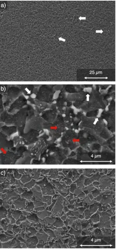
In this section, micrographs from electron microscopy are selected in order to present the main features of the microstruc tures resulting from the decomposition of the austenite in steels enriched with nitrogen, N and C + N. The microstructure of an N sample after 650 °C 1T for 3 h is shown in Fig. 4a and b. It mostly consists of equiaxed ferrite grains with a diameter of ca. 4 µm. Sorne regions that exhibit locally intense precipitation, which are revealed by the light grey contrast, are pointed by arrows in Fig. 4a. Such zones are examined more closely in Fig. 4b. EDS analysis in SEM allowed identifying the coarsest, micro-sized precipitates as carbides, which precipitated either separately or inside pearlite colonies. The ferrite grains contain fine precipitates indicated by red arrows in Fig. 4b. As will be seen below, these precipitates are CrN nitrides formed during the nitriding process. The microstruc ture in a C + N sample (0.59 wt%C-0.41 wt%N) also consists mostly of ferrite grains with similar size as in N sampi es as shown in Fig. 4c. The differences with N samples are the larger number of pearlite colonies, which are distributed more homogeneously, and the absence of isolated cementite precipitates. The higher number of pearlite colonies is due to the higher carbon concentration.
TEM micrographs of a representative pearlite colony and the surrounding ferrite grains in an N sample are shown in Fig. 5. High angle annular dark field (HAADF) STEM imaging suggests the presence of nitride precipitates which yield a darker contrast due to their lower overall atomic number compared to that of ferrite matrix. EDS maps reveal that these nitrides are chromium rich. They produce electron diffraction patterns consistent with the rock sait structure and lattice parameter of CrN. These precipitates exhibit three distinct morphologies: faceted, globular and as platelet. The largest ones ( =300 nm long, "" 100 nm wide) are faceted and located at a grain boundary between ferrite grains. Baker-Nütting orientation relationship between these large and facetted CrN and ferrite was observed in multiple occurrences, one example being shown in Fig. 6. Smaller globular CrN precipitates are located inside the ferrite grains, including the ferrite lamellae in pearlite. They correspond to the ones indicated by arrows in the SEM micrographs in Fig. 4b. Finally, CrN platelets a few nanometers thick can be found in ferrite grains adjacent to the pearlite colony, as can be seen in Fig. 7. However, high magnification micrographs of the pearlitic area revealed the ferrite lamellae are free of these nanometric CrN platelets as shown in Fig. 8. The thin platelets of CrN systematically show a Baker-Nütting OR.
High-resolution STEM image shown in Fig. 9 shows that the platelets maintain a high coherency with the matrix even at this temperature, leading to a high distortion of the ferritic lattice. Counting the precipitates on a large field-of-view micrograph {500 x 500 nm2) with known local thickness provided a rough estimation of the precipitate number density to the order of 1022 m-3 after nitriding and subsequent 1T at 600 °C for 2 h .
Both EDS and EELS chemical mappings, found in Figs. 6 and 8, indicate a degree of partitioning of chromium and manganese into cementite, respectively. lt should be noted here that the TEM lamella was taken from a sample held for 3 h at 650 °c during which partitioning could have occurred behind the austenite/ pearlite transformation interface [21.22].
The microstructure of a nitrided steel sample (N-quenched in Table 2) was observed after an 1T at 650 °C interrupted after 30 s, until the end of first stage, when 87% of austenite had decomposed and is shown in Fig. 10. ln addition to the three morphologies of CrN
Fig. 4. Secondary Electrons SEM micrographs of a,b) N sample (0.12 wt%C, 0.27 wt%N) isothermally held at 650 °C for 3 h. The white and red arrows show respectively the zones of cementite precipitation and the CrN precipitates inside ferrite grains. c) C + N sample (0.59 wt%C-0.41 wt%N) isothermally held at 600 °c for 20 min. (For inter pretation of the references to colour in this figure legend, the reader is referred to the Web version of this article.)
described above, a fourth morphology was found as shown in Fig. 10a and b. lt consists of lameltar CrN up to several hundreds of nanometers long and about 10 nm thick, originating from ferrite grain boundaries. These nitrides are generalty grouped into sets of nearly paraltel lameltae. The grains in which lameltae are found contain very few to no platelets, whereas in adjacent grains where
they are absent, the platelets are numerous as can be seen in Fig. 10c. The lameltae are in Baker-Nütting OR with ferrite and in side a given set of paraltel nitrides, there is one single variant as shown in Fig. 11, with interfaces paraltel to (100)a.-Fe//(100krN, One ferrite grain can contain several such groups.
3.4. Hardness measurements
Hardness measurements give a first overview of strengthening afforded by nitriding and carbonitriding treatments. Fig. 12 shows the Vickers hardness, which was measured (at room temperature) for ait steels after 1T bath above and below Bs. Hardness of N and C + N steels is significantly high. For instance, hardness of N-500 °C steel (IT above Bs) is about 500 HV, which is close to that of as quenched martensite in I steel (Table 3). Below Bs, hardness of C + N steel can reach about 700 HV, much higher than the hardness of C steel (500 HV). For any given 1T temperature, increased hard ness is obtained for 1, C, N and C + N steels. lt is noteworthy that the N steel presents similar or higher hardness than the C steel, although the C steel contains a larger fraction of interstitial: this highlights the strengthening effect of nitrogen. Considering sepa rately the steels with and without nitrogen, one observes the usual trend that higher amounts of interstitials increase the hardness. C steel is harder than I steel by about 100 HV, and C + N steel is harder than N steel. For ait the altoys, as expected the hardness increases when decreasing the 1T temperature.
4. Discussion
4.1. Microstructure
Similarly to the decomposition below Bs [11 ], a finer micro structure is obtained in the alloys containing nitrogen. The refine ment of the ferritic microstructure is likely due to the chromium nitrides that have precipitated in austenite during the enrichment at 900 °C, which probably acted as nucleation sites for ferrite. This is supported by the Baker-Nütting OR and the (100)a.-Fe//(100krN in terfaces observed between ferrite and faceted CrN as shown in Fig. 6. This is an indication that ferrite nucleated on these CrN as the orientation relationship and the trace of the interface gives a Tumbult-Vonnegut disregistry [23] of about 2% in the 650 °C-700 °C range, which should make CrN a patent nucleating agent for ferrite according to Bramfitt [24]. The presence of these CrN ni trides, located bath at prior y grain boundaries and inside the y grains [11 ], results in a higher total number of nucleation sites, which in tum leads to finer grains.
In total, four different morphologies of CrN chromium nitride were observed in nitrided samples: faceted, globular, platelet shaped and lameltar. The two first morphologies are thought to corne from the nitriding/carbonitriding enrichment process as they were observed in the quenched state following nitriding/carbon itriding [11]. They are often found in aggregates with AIN, VN and MnSiN2 [ 11 ]. Taking the three first types of precipitates into ac count, they have a broad size distribution: the faceted precipitates can exceed 1 µm in size white the platelets are no more than a few nanometers thick. No specific OR was found between the globular CrN and the ferritic matrix, possibly implying that their nucleation occurred in prior austenite and that they were subsequently sur rounded by ferrite during the transformation of the neighboring austenite. The morphology and OR of the platelets match exactly with the CrN precipitation occurring during ferritic-phase nitriding of Fe-Cr altoys [25,26] indicating that these precipitates nucleated inside the ferrite grains, after their formation. Precipitation of the CrN nitrides on the moving a/y interface is unlikely, because this would have led to some spatial organization of the nitrides and to
,
variant selection (see e.g. Ref. [271). A rough estimate of the nanosized CrN precipitates mass fraction based on a radius r of 5 nm, a thickness t of 3 nm and a number density N of 2 x 10²² m-3 gives a volume fraction fv = N1rr2t of 0.5%, for the N sample isothermally held at 600 °c for 2 h (Section 3.1 ). The mass fraction fm ,=,J..f;!""'0.4% is comparable to the McrN values reported in
Table 2. Hence, the majority of the CrN mass fraction increase calculated from HEXRD can be attributed to the precipitation of the CrN platelets. Growth of the CrN previously precipitated during the enrichment is likely to occur simultaneously, but the precipitation of the platelets must quickly consume the nitrogen remaining in solid solution.
The last morphology, lamellar chromium nitride, was exclu sively observed in an N alloy isothermally transformed for a very short time (30 s) after nitriding. lt also displays the Baker-Nütting orientation relationship and its interfaces are close to (100)/J.-Fe// (100)crN, which are thought to be low energy interfaces as explained above. Miyamoto et al. reported a comparable morphology and OR after plasma nitriding of Fe - 18 Cr for 5 h at 570 °c [28]. Here, the sample in which this morphology was observed was transformed for a short time (30 s). However, it turned that this sample also had a far superior nitrogen content than the other sample. Thus, it cannot be concluded whether this morphology results from the short holding time or from the high nitrogen content.
Regarding the influence of the 1T temperature on the micro structure, no clear trend could be established from our observa tions, conversely to the hardness measurements and the austenite decomposition kinetics. Qualitative analysis did not reveal any marked effect of the 1T temperature on the main features of the microstructure, namely the equiaxed ferrite grain size, or the pro portion, size and distribution of the nitrides. Quantitative analysis of the microstructure would likely reveal subtler changes but it is outside the scope of this study.
4.2. Thennodynamic analysis
At 600 and 650 °C, in both N and C + N steels, the austenite was fully decomposed after IT, in accordance with thermodynamic calculation (Table 1 ). Measured cementite mass fraction almost exactly matches the equilibrium value in C + N steel. There are more discrepancies for the N steel, because of the low amounts of cementite, which are close to the detection limit of XRD.
The measured CrN mass fractions never reached the equilib rium. As discussed above, the increase of fcrN during the ITs mostly cornes from the precipitation of CrN in ferrite. Although the coherent precipitation in ferrite of the nano-scaled nitrides may significantly affect the solubility limit (see e.g. Ref. (291), the dif ference with equilibrium is significant. lt is due to the sluggish diffusion of chromium and to the fact that the CrN nitrides cannot form without partition, contrary to the case of ferrite and cementite. Indeed, the amount of Cr substitution by Fe is smalt in CrN. This amount was not measured in platelet-shaped nitrides but it is inferior to 10% in the globular nitrides, which formed during the enrichment treatment [ 11 ]. Hence, the precipitation of CrN in ferrite was still ongoing at the end of the ITs. One can stress that during thermochemical treatments, the CrN amount in ferrite will significantly depend on the temperature evolutions, whereas Fig. 5. a) BF and b) HAADF STEM micrographs of nitrided sample isothermally transformed for 3 h at 650 °C with the c) EDS maps of N. Mn. Cr and C. They show a
pearlite colony, surrounding ferrite grains and CrN nitrides with three different mor phologies: large and faceted, smaller and globular as well as nanometric platelets. The nearly vertical streaks visible on a) and b) are artefacts related to lamella thickness variations stemming from the FIB preparation.
•
•
Vf9J«,�:::·. \( DOk,N•
•
•
. ( ,J Ü)u.Fc (lll)c, .•
·
·
·
.
�
·
··
•·
·
·
·
·
·
\•
•
•
•
Fig. 6. a) TEM micrograph of a coarse CrN precipitate and the adjacent ferrite grain in a nitrided sample isotherrnally transforrned for 30 s at 650 °C with b) the selected area diffraction (SAED) pattern of the interface along the (001 lo-Fe//(OÎl lcrN zone axis.
Fig. 7. HAADF STEM micrograph of the nitrided sample isotherrnally transformed for 3 h at 650 °C. It shows intragranular CrN nanoplatelets in a ferrite grain directly adjacent to a pearlite island visible in the upper right corner.
ferrite and cementite amounts will undergo less variations. At 700 °c in the N steel, the thermodynamic calculation predicts no cementite and significant amount of austenite (18.7 wt%). Indeed, 700 °C is above the Ae1 temperature, 683 °c (taken as the limit above which only a, y and CrN phases are stable). In contra diction with this calculation, cementite was detected and the austenite amount was 0.8 wt% (see Table 2), as if the "experimental" Ael temperature was superior to 700 °C. There is no interpretation of this discrepancy between calculated and actual Ael temperature. It was tried to take account of the austenite depletion in Cr and N by the CrN precipitates in the thermodynamic calculations, but this did not change the calculated Ael temperature significantly.
The mass fraction of platelet-shaped CrN nitrides that precipi tated inside the equiaxed ferrite grains after their formation is larger than expected from thermodynamic calculations, as
discussed in section 4.1. It is thought that the ferrite grains got temporarily supersaturated in nitrogen. Indeed, if one assumes that the growth of ferrite grains is controlled by diffusion and that local equilibrium holds at the a/y interface, the growing ferrite grains should reject most part of the nitrogen into the austenite. Ther modynamic equilibrium calculations predict that the concentration of nitrogen, which is kept inside the ferrite grains is around ten times lower than the concentration necessary to form the mass fraction of platelet-shaped CrN nitrides determined experimen tally. Assuming local paraequilibrium at the interface leads to the same order of magnitude.
For instance, let us consider the C + N steel and the 1T at 600 °c. The amount of platelet-shaped CrN according to HEXRD is equal to 0.3 wt% (McrN, Table 2, see also Section 4.1 ). To form such amount,
the nitrogen mass concentration that has to be kept inside the ferrite grains is equal to 7.4 10-4_ (Zero nitrogen solubility in ferrite is assumed with respect to CrN precipitation). If ferrite grows into austenite with local equilibrium at a/y interface,2 the nitrogen concentration in ferrite should be equal to 6.5 10-5• This amount is
about ten times too low. Similar orders of magnitude were obtained in the case of N steel. Hence so far there is no straightforward interpretation for the precipitation of the platelet-shaped CrN ni trides inside the equiaxed ferrite grains.
On the other hand, during the pearlite formation, it seems that nitrogen is rejected from the ferrite, as no platelet-shaped nitrides were found inside the ferrite of pearlite colonies. Further investi gation is required, in particular with interrupted treatments, to examine how the nitrogen distribution evolves inside the microstructure.
4.3. Phase transformation kinetics; sequence of austenite decomposition
Austenite decomposition in nitrogen-containing alloys was faster than in their nitrogen-free counterparts at comparable
2 This estimation was done by calculating a metastable equilibrium between a.
and y at 600 °C and by excluding CrN and cementite phases. The depletion in Cr and N by the CrN precipitates formed during the enrichment process was accounted for. In order to estimate possible evolution of the tie-Iine, DICTRA simulation of ferrite growth into austenite was carried out (in an Fe-C-N system). The operative tie-Iine evolved with time, but the nitrogen amount in ferrite kept the same order of magnitude. Assuming ferrite growth under paraequilibrium conditions leads to the same order of magnitude of nitrogen concentration in ferrite.
Fig. 8. a) ADF STEM micrograph of the pearlite colony in Fig. 5 with b) the EELS maps of the highlighted area in a). Small globular chromium nitrides are visible in the ferrite lamellae. The EELS maps also indicate some degree of Mn and Cr partitioning into the cementite lamellae.
Fig. 9. HAADF STEM high-resolution micrograph showing a CrN platelet in ferrite
along the (OOl)a-Fe//[OÎllcrN zone axis, in an N sample isotherrnally held at 600°C for 2 h. The platelet is highly coherent with the matrix and the mismatch between the two lattices induces distortions in both.
Table2
carbon content, in spite of a larger total content in y-stabilizing interstitials, as illustrated by Fig. 2. This faster transformation rate is thought to be related to the precipitation of CrN nitrides in two separate ways. First, the precipitates provide nucleation sites as explained in Section 4.1, which will enhance the nucleation rate of ferrite. Precipitation-induced dislocations could also facilitate the nucleation of ferrite. Additionally, the precipitation of CrN depletes the chromium in solid solution in austenite leading as well to a faster transformation rate (9,10). Finally, literature results show that chromium causes substantial solute drag during the partitionless transformation of austenite into ferrite (30-32), which slows down the transformation. The chromium mobilized in precipitates no longer causes solute drag, which might contribute to the acceler ation of ferrite formation.
Besides the accelerating effect of the CrN nitrides, the expected slowdown of the ferrite formation with increasing amount of in terstitials was observed: a slower rate was observed in C + N steel than in N steel during the first stage. In N steel, the faster trans formation rate at 600 °c than at 500 and 700 °c reflects the inverse temperature dependence of the driving force and the diffusion associated with nucleation and growth process. The absence of variation of the ferrite grain size with 1T temperature suggests that the number of CrN nitrides enhancing ferrite nucleation did not vary significantly with temperature.
Fig. 13 schematizes the proposed sequence of austenite decomposition in nitrogen-enriched steels. a) During the enrich ment, CrN nitrides precipitate at prior austenite grain boundaries and inside the grains. b) Ferrite grains nucleate on the CrN nitrides.
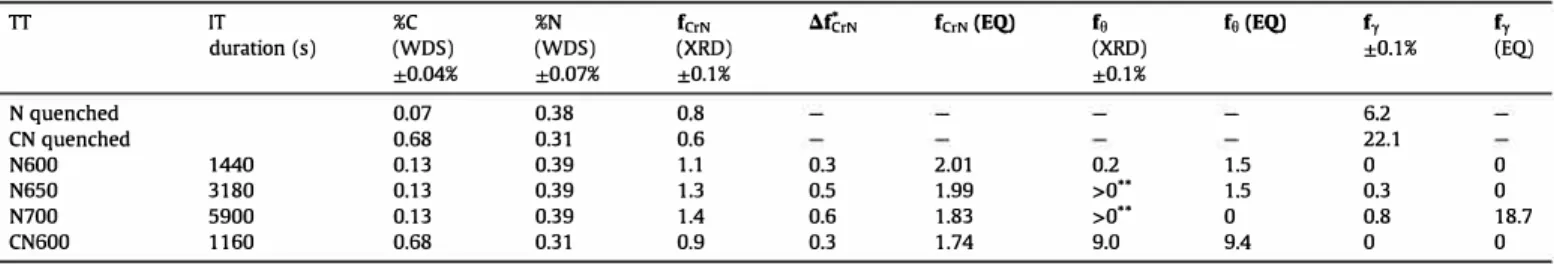
Concentration of nitrogen and carbon in solid solution in the matrix before IT, CrN mass fraction (fc,Nl and increase during IT (t:.fc,N), mass fraction of cementite (fa) and austenite ( fy ). TT IT %C %N fcrN duration (s) (WDS) (WDS) (XRD) ±0.04% ±0.07% ±0.1% N quenched 0.07 0.38 0.8 CN quenched 0.68 0.31 0.6 N600 1440 0.13 0.39 1.1 N650 3180 0.13 0.39 1.3 N700 5900 0.13 0.39 1.4 CN600 1160 0.68 0.31 0.9
• t:.fc,N = fc,N ( end of IT) - fc,N(N or CN quenched ) .
.. Cementite peaks could be discemed but the amount could not be quantified. EQ: equilibrium value.
àfêrN fc,N {EQ) fo fa {EQ) fy fy (XRD) ±0.1% (EQ) ±0.1% 6.2 22.1 0.3 2.01 0.2 1.5 0 0 0.5 1.99 >0 .. 1.5 0.3 0 0.6 1.83 >0 .. 0 0.8 18.7 0.3 1.74 9.0 9.4 0 0
Fig. 10. a) Bright field STEM micrograph of a nitrided sample after 1T at 650 °C for 30 s b) EDX map of Cr for the region containing CrN lamellae, highlighted in blue in a). c) HAADF STEM micrograph of the region containing CrN platelets, highlighted in red in a). (For interpretation of the references to colour in this figure legend, the reader is referred to the Web version of this article.)
b
•
•
-·-···a-Fè C,N•
•
•
•
Fig. 11. a) Bright field TEM micrograph of the lamellar CrN morphology. b) SAD pattern of the area in a) showing the Baker-Nütting OR between ferrite and CrN. c) Dark field TEM micrograph of the same area as in a) recorded using the diffracted beam circled in b).
800 700 600 êi 500 0 0 400 ::::. 300 200 100 0 1
•
C•
1, N•
0 C+N•
0 1. 1• 0 1. 0'
0 • 0'
0•
..
'
•
1•'
0-
•
1• 300 350 400 450 500 550 600 650 700 T (°C)-Fig. 12. Vickers hardness measurements (load 100 g) after 1T vs. 1T temperature, for I,
C, N and C + N steels. ITs with incomplete transformations (T > Ael range or bainitic range close to Bs) are not represented.
(Possible nucleation on the intragranular CrN nitrides has to be established). The growing ferrite grains reject carbon into the austenite, leading in la ter stages ( c) to the precipitation of carbides outside the ferrite grains, only in N steel, and to the formation of pearlite colonies in both N and C + N steels. On the other hand, the ferrite grains keep a significant part of the nitrogen and hence get temporarily supersaturated. Nano-scale CrN precipitation takes place inside the ferrite grains in a short time, e.g. within 30 s at 650 °C in an N steel (Fig. 10).
The carbides and the pearlite probably form only once the austenite is sufficiently enriched in carbon. This is the case in the I
Table3
Ms, Mf temperatures and hardness of martensite in I, C and C + N steels after quench experiments in dilatometer ( quench with liquid nitrogen for C and C + N steels ). N steel transforrned too fast to avoid bainitic transformation.
Steel C C+N Ms (°C) 390 260 205 Mf(°C) 240 -30 -105 Hv 530 880 900
a
b
Fig. 13. Schematic of the proposed austenite decomposition sequence in nitrogen-enriched steels. a) During the enrichment, precipitation of CrN nitrides located both at prior austenite grain boundaries and inside the austenite grains; b) Heterogeneous nucleation of ferrite grains at the CrN nitrides; growth of ferrite grains into austenite with rejection of carbon; precipitation of CrN inside ferrite; c) precipitation of carbides in the austenite enriched in carbon (only in N steel); formation of pearlite colonies.
steel whose kinetics exhibits the usual two stages (Fig. 2) associated with the successive formation of ferrite and pearlite. Nevertheless, in nitrogen-enriched steels, no clear change of global kinetics could be ascribed to the formation of the carbides and the pearlite. lndeed, the C + N steel exhibits one single-stage kinetics. As for the N steel, which exhibits two-stage kinetics, microstructure obser vations at the end of first stage (IT at 650 °C for 30 s, Fig. 10) proved insufficient to establish the origin of the slow-down of the trans formation rate. Further observations are necessary to establish at which stage the carbides and the pearlite are formed.
4.4. Hardness/microstructure relationship
lt is thought that the higher hardness in nitrogen-containing steels compared to nitrogen-free steels cornes in large part from the nanoscale CrN nitrides. For instance, let us consider the I and N steels isothermally held at 600 °c, whose hardness are respectively 210 and 400 HV. The microstructure ofl steel is composed of ferrite and pearlite (65% pearlite) whereas the microstructure of N steel contains mainly ferrite grains with intragranular nano-scaled CrN precipitates. Even if we take into account the smaller ferrite grain size in N steel (4 µm) in comparison with the I steel, the main strengthening effect is attributed to the nanoscale nitrides. If we compare N steel with C steel, the hardness of N steel ( 400 HV) is also higher than the hardness of C steel (350 HV) which is fully pearlitic after 1T at 600 °C. Finally, C + N steel has the highest hardness at 600 °C because it contains significant amount of both pearlite and ferrite grains strengthened by CrN nitrides. For higher temperatures, hardness of N and C steels become similar or even lower for N steel. To interpret this, one should consider more pre cisely the evolution with temperature of size and density of CrN nitrides as well as of interlamellar spacing of pearlite.
5. Conclusion
The effect of N or C + N enrichment in the austenitic field of a low-alloyed 23MnCrMo5 steel on the decomposition of austenite has been examined under isothermal conditions in the tempera ture range 600-700 °C. It was found that:
• The rate of austenite decomposition is much faster in nitrogen containing steels (N or C + N) than in initial and carburized (I and C) steels.
• Contrary to the usual ferritic-pearlitic microstructures that occur in I and C steels, the microstructures in N and C + N steels are finer and dominated by a distribution of small (ca. 4 µm) equiaxed ferrite grains.
• CrN chromium nitride prec1p1tation during the enrichment treatment is responsible for both effects. First, CrN precipitates enhance ferrite nucleation rate, which explains the fine grains and faster transformation rate. The precipitation of CrN also consumes the chromium in solid solution in austenite, contributing to its faster transformation rate as well.
Apart from ferrite, the other products of austenite decomposi tion are cementite and new CrN nitrides, which precipitated inside the ferrite grains in the form of nanosized platelets in Baker Nütting OR with ferrite:
• Their high volume fraction suggests a transient but elevated supersaturation of ferrite in nitrogen when it forms from the decomposing austenite, which could not be explained using classical ferrite growth models.
• They markedly increase the hardness in N and C + N steels, compared to I and C steels. In C + N, the numerous pearlite colonies contribute to strengthening as well.
The only obvious effect of 1T temperature on microstructures is that they radically differ from those obtained below Bs (T � 450 °C) [11 ]. Otherwise, further investigation remains necessary to estab lish quantitatively the effect of the 1T temperature on microstruc tures, given the clear evolution of hardness and austenite decomposition kinetics.
Acknowledgments
This work was supported by PSA and by the French State through the program "Investment in the future" operated by the National Research Agency (ANR) and referenced by ANR-11-IABX-0008-01 (LabEx DAMAS).
The experiments were performed on beamline ID15B at the European Synchrotron Radiation Facility (ESRF), Grenoble, France. We are grateful to Thomas Buslaps at the ESRF for providing assistance in using beamline ID15B.
Appendix A. Supplementary data
Supplementary data related to this article can be found at https: //doi.org/10.1016/j.actamat.2018.02.008.
References
[1] A. Constant, G. Henry, j.-C. Charbonnier, Principes de base des traitements thermiques, thermomécaniques et thermochimiques des aciers, PYC Édition, 1992.
[2] B.N. Bose, M.F. Hawkes, Kinetics of the eutectoid transformation in alloys of iron and nitrogen, Trans. AIME 188 (1950) 307-316.
[3] N. Nakada, N. Fukuzawa, T. Tsuchiyama, S. Takaki, T. Koyano, T. lwamoto, Y. Omori, Isothermal transformation in Fe-N hypereutectoid alloy, ISIJ Int. 53 (2013) 139-144.
[ 4] j. Foct, P. Rochegude, A. Hendry, Low temperature ageing of Fe-N austenite, Acta Metall. 36 (1988) 501-505.
[5] Z. Jiang, X. Li, J. Gu, M. Hu, Z. Zhu, lsothermal decomposition behavior of the high nitrogen concentration y-Fe[N] prepared from pure iron, Appl. Surf. Sei. 254 (2008) 7361-7364.
[6] D. Jiao, C.P. Luo, J. Liu, Isothermal transformation of high-nitrogen austenite, Ser. Mater 56 (2007) 613-616.
[7] D. Jiao, C. Luo, J. Liu, G. Zhang, Morphology and crystallographic orientation relationship in isothermally transformed Fe-N austenite, Mater. Charact 88 (2014) 52-57.
[8] H. Gôhring, S. Kante, A. Leineweber, E.J. Mittemeijer, Microstructural devel opment and crystallographic properties of decomposing Fe-N-C compound layers, lnt. J. Mater. Res. 107 (2015) 203-216.
[9] A. Simon, A. Lorenzo, G. Beck, A. Lallemant, Influence des éléments d'alliage sur la décomposition au cours de la trempe de l'austénite carbonitrurée en phase gazeuse, Mém. Sei. Rev. Métallurgie 71 (1974) 851-869.
[10] A. Simon, A. Lorenzo, G. Beck, G. Meynet, Influence de la teneur en azote sur les transformations de l'austénite carbonitrurée de l'acier 30 CD 4, Mém. Sei. Rev. Métallurgie 71 (1974) 823-831.
[11] S.D. Catteau, H.P. Van Landeghem, J. Teixeira, J. Oulcy, M. Dehmas, S. Denis, A. Redjaïmia, M. Courteaux, Carbon and nitrogen effects on microstructure and kinetics associated with bainitic transformation in a low-alloyed steel, J. Alloys Compd 658 (2016) 832-838.
[12] S.D. Catteau, S. Denis, J. Teixeira, J. Oulcy, M. Dehmas, A. Redjaïmia, M. Courteaux, Effects of carbon and nitrogen on isothermal transformations of austenite in a low alloyed steel, in: H.-W. Zoch, R. Schneider, T. Lübben (Eds.), Proc. 21 st IFHTSE Congr, A WT, Munich, Germany, 2014, pp. 153-161. [ 13] G.F. Bas tin, H.J.M. Heijligers, Quantitative electron probe microanalysis of
carbon in binary carbides. 1-principles and procedures, X Ray Spectrom. 15 (1986) 135-141.
[ 14] F. Robaut, A. Crisci, M. Durand-Charre, D. Jouanne, Practical aspects of carbon content determination in carburized steels by EPMA, Microsc. Microanal. 12 (2006) 331-334.
[15] J. Ruste, P. Billard, Analyse du carbone en faible concentration dans les aciers, J. Microsc. Spectrosc. Électroniques 11 (1986) 255-260.
[16] S. Catteau, Effets du carbone et de l'azote sur les cinétiques de décomposition de l'austénite dans un acier faiblement allié; Etude expérimentale et modé lisation, 2017. http:/fwww.theses.fr/s183520. (Accessed 15 December 2017).
[17] J. Kunze, Nitrogen and Carbon in Iron and Steel: Thermodynamics, Akad. Verlag, 1990.
[18] J. Rodriguez-Carvajal, Recent advances in magnetic structure determination by neutron powder diffraction, Phys. B Condens. Matter 192 ( 1993) 55-69. [19] K. Iakoubovskii, K. Mitsuishi, Y. Nakayama, K. Furuya, Mean free path of in
elastic electron scattering in elemental solids and oxides using transmission electron microscopy: atomic number dependent oscillatory behavior, Phys. Rev. B 77 (2008), 104102.
[20] L Cheng, N.M. Van Der Pers, A. Bôttger, T.H. De Keijser, E.J. Mittemeijer, Lattice changes of iron-nitrogen martensite on aging at room temperature, Metall. Trans. A 21 (1990) 2857-2867.
[21] NA. Razik, G.W. Lorimer, N. Ridley, An investigation of manganese parti tioning during the austenite-pearlite transformation using analltical electron microscopl, Acta Metall. 22 (1974) 1249-1258.
[22] N.A. Razik, G.W. Lorimer, N. Ridley, Chromium partitioning during the austenite-pearlite transformation, Metall. Trans. A 7 (1976) 209-214. [23] D. Turnbull, B. Vonnegut, Nucleation catalysis, Ind. Eng. Chem. 44 (1952)
1292-1298.
[24] B. Bramfitt, The effect of carbide and nitride additions on the heterogeneous nucleation behavior of liquid iron, Metall. Trans. 1 (1970) 1987-1995. [25] M. Sennour, C. Jacq, C. Esnouf, Mechanical and microstructural investigations
of nitrided Fe-Cr layers, J. Mater. Sei. 39 (2004) 4533-4541.
[26] A.R. Clauss, E. Bischoff, S.S. Hosmani, R.E. Schacherl, E.j. Mittemeijer, Crystal structure and morphology of mixed Crl-x Al x N Nitride precipitates: gaseous nitriding of a Fe-1.5 Wt Pet Cr-1.5 Wt Pet Al alloy, Metall. Mater. Trans. A 40 ( 2009) 1923-1934.
[27] M.-Y. Chen, H.-W. Yen,j.-R. Yang, The transition from interphase-precipitated carbides to fibrous carbides in a vanadium-containing medium-carbon steel, Ser. Mater 68 (2013) 829-832.
[28] G. Miyamoto, A. Yonemoto, Y. Tanaka, T. Furuhara, T. Maki, Microstructure in a plasma-nitrided Fe-18 mass% Cr alloy, Acta Mater. 54 (2006) 4771-4779. [29] N. Vogel, A. Hazotte, J. Oulcy, H. Michel, S. Denis, Internai mismatch stresses
associated with CrN precipitation in nitriding layers of Fe-Cr alloys, in: S. Denis, J.-L. Lebrun, B. Bourniquel (Eds.), Proc. Fourth Eur. Conf. Residual Stress, 1996, pp. 921-930. Cluny.
[30] M. Enomoto, Comparison of alloy element partition behavior and growth kinetics of Proeutectoid ferrite in Fe-C-X alloys with diffusion growth theory, Trans. Iron Steel lnst. Jpn 28 (1988) 826-835.
[31] J.V. Bee, R.W.K. Honeycombe, The isothermal decomposition of austenite in a high purity Iron-Chromium binary alloy, Metall. Trans. A 9 (1978) 587-593. [32] R.A. Ricks, P.D. Southwick, P.R. Howell, The effect of chromium and nickel on the y-HJ. phase transformation in steels and iron-base alloys, J. Microsc 124 (1981) 23-35.