HAL Id: hal-01365743
https://hal.archives-ouvertes.fr/hal-01365743
Submitted on 4 Oct 2017
HAL is a multi-disciplinary open access
archive for the deposit and dissemination of
sci-entific research documents, whether they are
pub-lished or not. The documents may come from
teaching and research institutions in France or
abroad, or from public or private research centers.
L’archive ouverte pluridisciplinaire HAL, est
destinée au dépôt et à la diffusion de documents
scientifiques de niveau recherche, publiés ou non,
émanant des établissements d’enseignement et de
recherche français ou étrangers, des laboratoires
publics ou privés.
Elaboration of metal organic framework hybrid
materials with hierarchical porosity by electrochemical
deposition–dissolution
Chompunuch Warakulwit, Sudarat Yadnum, Chaiyan Boonyuen, Chularat
Wattanakit, Aleksandar Karajic, Patrick Garrigue, Nicolas Mano, Darren
Bradshaw, Jumras Limtrakul, Alexander Kuhn
To cite this version:
Chompunuch Warakulwit, Sudarat Yadnum, Chaiyan Boonyuen, Chularat Wattanakit, Aleksandar
Karajic, et al.. Elaboration of metal organic framework hybrid materials with hierarchical porosity by
electrochemical deposition–dissolution . CrystEngComm, Royal Society of Chemistry, 2016, 18 (27),
pp. 5053-5226. �10.1039/C6CE00658B�. �hal-01365743�
Elaboration of metal organic framework hybrid
materials with hierarchical porosity by
electrochemical
deposition–dissolution
Chompunuch Warakulwit,
aSudarat Yadnum,
bChaiyan Boonyuen,
aChularat Wattanakit,
fAleksandar Karajic,
cPatrick Garrigue,
cNicolas Mano,
dDarren Bradshaw,
eJumras Limtrakul
fand Alexander Kuhn*
cRationally designed hierarchical macro-/microporous HKUST-1 electrodes were prepared via an electro-chemical deposition–dissolution technique with the motivation to overcome diffusion limitations that typi-cally occur for conventional microporous MOFs. A colloidal crystal of silica spheres was prepared by the Langmuir–Blodgett (LB) technique. Using this crystal as a template, macroporous copper electrodes with a controlled number of pore layers were prepared via electrodeposition. After the removal of the template, the synthesis of HKUST-1 was performed via partial anodic dissolution of the copper surface in the pres-ence of an organic linker, leading to the deposition of HKUST-1 on the electrode surface with the designed macroporous structure. The macroporous Cu electrodes do not only behave as structural templates but are also the Cu source for the formation of MOFs. The applied potential and deposition time allow the characteristics of the porous layer to be fine-tuned. The developed synthesis is rapid, occurs under mild conditions and therefore opens up various potential applications including catalysis, separation and sensing based on these hierarchical materials.
Introduction
Metal–organic frameworks (MOFs) are crystalline and porous solid materials with a framework composed of metal ions and organic linkers.1Owing to their unique properties such as well-defined structures, uniform and stable pores, large pore vol-ume, high surface area, and tunable surface chemistry,1MOFs have been considered as interesting candidate materials for various applications including adsorption,2 separation,2–4 cap-ture,3,5storage,6biomedical imaging,7drug delivery,8catalysis,9
recognition,10 sensing,11 and electronic devices.12MOFs have also been found to be of great importance in a large variety of electrochemical applications,13and have been applied as mate-rials for electrocatalysis,14,15 electrochemical sensing16,17 and in supercapacitors.18 Recently, it has been reported that the method of synthesizing MOFs has an effect on their electro-chemical behavior due to varying amounts of impurities and molecular guests in the final products.19 This illustrates that the choice of the synthetic route is of primary importance for the performance of the obtained material.
As conventional MOFs have sole micropores and large crystal sizes, many molecules with relatively large dimensions compared to the pore size of MOFs can experience severe dif-fusion limitations when penetrating the framework. In order to improve their performance, various synthetic strategies have been employed to create MOFs with pores of increased size such as mesopores (2–50 nm) and macropores (>50 nm),20–24 thus allowing shorter diffusion path lengths when they are used as thin films, nanoaggregates or nanoparticles.20,25–28 It also has been pointed out recently that structuring of MOFs in a hierarchical order opens up new opportunities to improve the material performance via the design of their physical form rather than altering the chemical components.29 However, to the best of our knowl-edge, there are so far no reports on the electrochemical syn-thesis of MOFs with the goal of obtaining a well-defined
aDepartment of Chemistry, NANOTEC Center for Nanoscale Materials Design for
Green Nanotechnology and Center for Advanced Studies in Nanotechnology and its Applications in Chemical, Food and Agricultural Industries, Kasetsart University, Bangkok 10900, Thailand
bCorporate Technology Office, The Siam Cement Public Company Limited,
Bangkok, 10800, Thailand
cCNRS UMR 5255, Bordeaux INP, ENSCBP, Univ. Bordeaux, 33607 Pessac Cedex,
France. E-mail: kuhn@enscbp.fr
dCentre de Recherche Paul Pascal, UPR 8641, CNRS - University of Bordeaux,
Ave-nue Albert Schweitzer, 33600 Pessac, France
eSchool of Chemistry, University of Southampton, Highfield, Southampton, SO17
1BJ, UK
fSchool of Energy Science and Engineering & School of Molecular Science and
Engineering, Vidyasirimedhi Institute of Science and Technology, Rayong 21210, Thailand
† Electronic supplementary information (ESI) available: General experimental synthesis and characterization protocols. See DOI: 10.1039/c6ce00658b
higher order porosity, which can be crucial for their integra-tion into practical devices.30–33Such well-organized hierarchi-cal pore architectures would allow a straightforward access to thin films of MOFs with a high microstructural homogeneity.
HKUST-1 is a MOF with a cubic framework structure and an open 3D pore system obtained by linking copperIJII) (Cu2+)
paddlewheel dimers and 1,3,5-benzenetricarboxylic acid (BTC) ligands.34HKUST-1 (Cu–BTC or Cu3(BTC)2) has Lewis acid Cu
sites that are accessible for molecules, thus offering various applications ranging from gas adsorption and separation,35 to gas storage,36,37 gas sensing,38,39 catalysis,28,40,41 and electrocatalysis.15 Recently, HKUST-1 was synthesized via electrochemical routes,15,42 and compared to other prepara-tion methods, electrochemistry has several advantages in-cluding shorter operation times, milder conditions43and bet-ter control over the synthesis in a continuous manner.44 In addition, it allows the direct formation of thin films, which are of particular interest for adsorption, catalysis, separation and sensing,42using a rather simple elaboration strategy.45
We present in this work a direct method for the fabrica-tion of a three-dimensional (3D) hierarchically structured macro-/microporous HKUST-1 composite material via an electrochemical deposition/dissolution technique (Scheme 1). It is based on the use of a colloidal template composed of 1 μm-silica spheres of narrow size distribution prepared via the Langmuir–Blodgett (LB) technique, followed by electrodeposi-tion of a precursor metal. Subsequently, a thin film of HKUST-1 (thickness ∼1.5 μm) with a well-defined inverse opal structure and a direct contact to the structured underly-ing metal phase was successfully prepared by controlled an-odization. The obtained highly controllable structures open up new perspectives for MOFs in various applications due to improved transport properties in the supported MOF matrix.
Results and discussion
As suggested by cyclic voltammetry (CV) measurements, the suitable potential for Cu deposition is in the potential range from 0.00 V to−0.47 V. Before generating macroporous cop-per, we first optimized the deposition conditions for a non-templated growth in order to identify which potential within this range leads to the smoothest copper deposit. Cu surfaces were generated with varying potentials ranging from−0.35 to
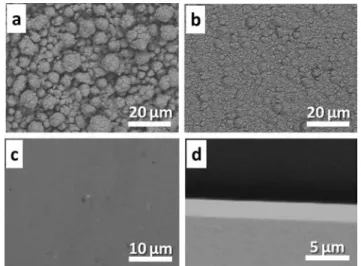
−0.006 V (−0.35, −0.30, −0.25, −0.20, −0.05, −0.025, −0.012, and−0.006 V). Some SEM images of the corresponding sam-ples are shown in Fig. 1. At relatively high negative potential values (−0.35 to −0.20 V), the Cu surfaces are not smooth (Fig. 1a and b), suggesting that the nucleation and growth of Cu is too fast. However, when the potential is increased to −0.05 V, a smooth Cu surface could be obtained (Fig. 1c), which is further confirmed by the cross section image of the film (Fig. 1d). An additional increase of the applied potential to−0.025, −0.012 and −0.006 V does not result in a significant change of the smoothness of the surface. The SEM images of these samples (not shown) are comparable; only the thick-nesses of the Cu layer are different. Therefore, we selected a potential of −0.05 V to generate the macroporous Cu electrodes required in the next step.
For the formation of the macrostructured electrode, cop-per has been grown to a thickness corresponding to 3/2 silica bead layers. This should allow an ordered macroporous hy-brid Cu/MOF film with a well-defined and open pore struc-ture to be provided. The deposition time needed to reach such a thickness was estimated by performing Cu deposition on a smooth surface at a constant potential of−0.05 V.
Fig. 2 shows the SEM images of the deposited macro-porous Cu obtained after the removal of the silica template with hydrofluoric acid. As expected, the layer thickness of Cu was found to increase with increasing deposition time. For a relatively short deposition time of 300 s, although the porous character is visible, it is not possible to create well-ordered pores under these conditions (data not shown). Increasing the deposition time to 700 s allows ordered macropores to be observed in the top view, but the cross sectional SEM image shows that the thickness of the Cu deposit is less than 1/2 of a silica bead layer. With a deposition time of 900 s, a complete 1/2 layer of Cu pores is obtained (Fig. 2a and b). The macropores were found to have a highly-organized hex-agonal arrangement corresponding to a well-defined inverse
Scheme 1 Schematic illustration showing the experimental steps performed in this work for the synthesis of the hierarchical macro-/ microporous HKUST-1.
Fig. 1 Typical SEM images showing (a–c) the top surface and (d) cross-section of the Cu deposit using a Cu plating bath (CUBRAC 660) at various potentials: (a)−0.35, (b) −0.25 and (c–d) −0.05 V. The deposi-tion time was 300 s.
opal structure. The pore diameter corresponds to the diame-ter of the silica template particles, analogous to what has been reported for other macroporous metal electrodes.46,47 For a deposition time of 2300 s, the desired ordered Cu macropores with a 3/2 layer thickness are obtained (Fig. 2c and d). For this reason, we used a deposition time of 2300 s and a potential of−0.05 V for the synthesis of all the Cu electrodes employed as starting materials for the prepara-tion of the structured MOF.
In order to optimize the conditions for the transformation of metallic Cu into HKUST-1, Au-coated slides modified with a flat Cu layer having a thickness equal to that of the desired porous electrodes (∼1.5 μm) were first used. The electrodes were pretreated in 10% H2SO4for 15 min before their use as
working electrode. A silver wire and a platinum mesh were employed as the pseudo reference and counter electrodes, re-spectively. A solution of 0.05 M BTC in ethanol with 0.2 M tributylmethylammonium methylsulfate (MTBS) as a supporting salt was used as the electrolyte.
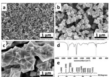
The transformation of Cu into HKUST-1 was carried out for a constant time (300 s) but with varying potentials of 0.125, 0.25 and 0.5 V. By using a potential of 0.125 or 0.25 V, the obtained products exhibited a microcrystalline character (Fig. 3a). When the applied potential is increased to 0.5 V, the size of the crystals with an octahedral block-like shape in-creases (Fig. 3b). This finding corresponds well to previous literature reports for electrochemically deposited HKUST-1.43,48For this reason, we used 0.5 V for the further transfor-mation of Cu into HKUST-1.
In the next optimization step, we tried to understand the influence of the deposition time on the product characteris-tics. Fig. 4a–c show the SEM images of HKUST-1 formed on the Cu surface at a constant potential of 0.5 V, but for various
times. The products look more crystalline, the octahedral crystal structure becomes better defined, and the size of the crystals increases from one hundred nanometers to a few micrometers when the deposition time increases from 60 s to 1800 s.
The HKUST-1 deposits obtained after a reaction time of 1800s were subsequently characterized by FTIR and XRD. For IR (Fig. 4d), the band in the range of 1560–1440 cm−1 is assigned to the asymmetric stretching vibrations of the BTC carboxylate groups. The symmetric vibrations centered at 1370 cm−1and the peaks at 730 and 760 cm−1are assigned to the phenyl group in the HKUST-1 structure. Most impor-tantly, the band at 1690–1730 cm−1, which is assigned to the acidic CO stretching vibration, characteristic of the free BTC linker, was not found, thus suggesting the complete de-protonation during the complexation of the linker molecules with the Cu2+ions.49For XRD (Fig. 4e), the diffraction peak positions and the relative diffraction intensities in the XRD pattern of the 1800s sample correspond well to what has been reported for HKUST-1 in the literature,50 thus confirming the successful preparation of HKUST-1 under these conditions.
Fig. 2 Low and high (inset) magnification SEM images showing the top surface of the ordered macroporous Cu electrodes (a, c) after the removal of the colloidal crystal template, obtained for an applied potential of−0.05 V but with various deposition times of (a) 900 and (c) 2300 s. Cross section images of deposits with a thickness of 1/2 and 3/2 layers of pores are shown in (b) and (d) for deposition times of 900 and 2300 s, respectively.
Fig. 3 SEM images showing the MOF products formed on flat Cu surfaces via electrochemical dissolution for different potentials, (a) 0.125 and (b) 0.5 V, but using the same reaction time (300 s) in a solution of 0.05 M BTC in ethanol containing 0.2 M MTBS as the supporting electrolyte.
Fig. 4 (a–c) SEM images showing the MOF products formed on flat Cu surfacesvia its electrochemical dissolution at 0.5 V for various times: (a) 60, (b) 600 and (c) 1800 s in a solution of 0.05 M BTC in ethanol containing 0.2 M MTBS as the supporting electrolyte. (d) FTIR and (e) XRD patterns recorded with the 1800 s sample confirming the HKUST-1 structure.
After this initial screening of the experimental conditions, we prepared HKUST-1 directly on the surface of macroporous Cu electrodes with 3/2 pore layers. A relatively short deposi-tion time of 60 s was chosen in order to ensure that the macroporous copper will transform only partly into HKUST-1, thus preserving the underlying macroporous architecture. Ap-plication of a potential of 0.5 V triggers the electrochemical oxidation of Cu0to Cu2+via several intermediate steps which have been recently investigated in detail.51 The produced Cu2+species interact with the BTC molecules in the solution leading to an observable precipitation of the solid material with its characteristic blue color, similar to what has been ob-served previously.52Although the SEM images reveal the uni-form distribution of HKUST-1 on the surface of the macro-porous electrode with a morphology similar to what has been obtained in the case of flat Cu-coated electrodes, Fig. 5 never-theless indicates an important alteration of the macropores due to the extensive formation of HKUST-1. In order to pre-vent this too rapid erosion and better preserve the originally designed macropores, the applied potential was decreased to 0.125 V for subsequent experiments.
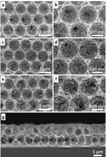
The SEM images of Fig. 6a–f show the top surface of the electrode after the anodic dissolution process at this lower potential of 0.125 V for various experimental times ranging from 30 s to 120 s. In this case, the originally designed macroporous structure could be entirely preserved. As expected, the amount of MOF and its morphology vary when the deposition time changes, analogous to experimental ob-servations on flat electrodes. The amount of the MOF product increases and the crystal facets are better defined with in-creasing deposition time. The obtained results indicate the successful preparation of a hierarchical macroporous HKUST-1 composite electrode via the currently employed technique. It should be noted that the desired hierarchically structured Cu/HKUST-1 composite electrode can be obtained in a relatively short reaction time (<120 s), thus the employed approach is straightforward and rapid. The cross sectional image of the 60 s sample (Fig. 6g) also confirms the preservation of the originally designed macroporous struc-ture. AFM images further indicate the presence of MOF (white deposit in Fig. S4†), although it is difficult to resolve its microstructure due to the high aspect ratio of the pores and the crystallites.
Conclusions
Rationally designed hierarchical macro-/microporous HKUST-1 composite electrodes were prepared via an electrochemical deposition–dissolution technique. Silica spheres were first used to prepare a colloidal crystal template by the Langmuir– Blodgett technique. Macroporous copper electrodes with a controlled thickness were obtained via electrodeposition. Af-ter removal of the template, the synthesis of HKUST-1 was performed via partial anodic dissolution of the copper sur-face in the presence of an organic linker, leading to the for-mation of the MOF on the electrode surface. The macro-porous Cu electrodes do not only behave as a structural template, but also as a metal source for the formation of the MOF. The applied potential and deposition time play impor-tant roles in the structural characteristics of the final prod-uct. Therefore, these parameters were optimized in order to transform only partially the well-organized macroporous Cu electrodes into a macroporous MOF architecture. We found
Fig. 5 (a, b) Low and high-magnification SEM images showing the top view of the macroporous Cu electrodes with 3/2 layers of pores after the MOF formation at a constant oxidation potential of 0.5 V and a re-action time of 60 s in a solution of 0.05 M BTC in ethanol containing 0.2 M MTBS as the supporting electrolyte.
Fig. 6 (a–f) Top view SEM images at low and high magnifications showing the MOF products formed on the walls of the ordered macroporous Cu electrodes (3/2 layers of pores),via the oxidation at 0.125 V for various reaction times (a–b) 30 s, (c–d) 60 s and (e–f) 120 s in a solution of 0.05 M BTC in ethanol containing 0.2 M MTBS as the supporting electrolyte. (g) Typical cross sectional image obtained for the 60 s sample.
that the desired hierarchically structured Cu/HKUST-1 com-posite electrode can be obtained in a relatively short reaction time (<120 s) at an optimized potential of 0.125 V. Thus, the employed technique is not time-consuming, uses only very mild electrochemical conditions and is easy to implement. It therefore represents an interesting enrichment of the already existing tool box employed to generate structured high per-formance MOF layers.53,54 Even though we exemplified the approach in the present work with only one type of MOF, the method should be easily transposed to all other MOFs that can be electrochemically generated by anodic dissolution.30 The obtained composite structures should allow these mate-rials to be used advantageously when diffusional transport problems would otherwise be a limiting factor, as it might be the case for several applications including catalysis, sensing or separation and storage of gases.55
Acknowledgements
We wish the thank Dr. Stephane Reculusa for helpful discus-sion. The Thailand Research Fund (TRF) is acknowledged for a Royal Golden Jubilee Ph.D. Fellowship (3.C.KU/51/A.1) and the French Government for its contribution to the Ph.D. cotutelle program. The National Nanotechnology Center (NANOTEC), National Science and Technology Development Agency, Thailand, is also acknowledged (for NANOTEC Center for Nanoscale Materials Design for Green Nanotechnology). DB thanks the European Research Council (ERC) for financial support (BIOMOF-258613). AK acknowledges support from the Institut Universitaire de France. Partial support has also been obtained within the frame of the Laboratory of Excellence AMADEus with the reference ANR-10-LABX-0042-AMADEUS. C. W. is grateful for support from the Junior Research Fellow-ship Program of the French Embassy in Thailand.
Notes and references
1 S. Kitagawa, R. Kitaura and S. Noro, Angew. Chem., Int. Ed., 2004,43, 2334–2375.
2 J.-R. Li, R. J. Kuppler and H.-C. Zhou, Chem. Soc. Rev., 2009,38, 1477–1504.
3 Y. S. Bae and R. Q. Snurr, Angew. Chem., Int. Ed., 2011, 50, 11586–11596.
4 J. R. Li, J. Sculley and H. C. Zhou, Chem. Rev., 2012,112, 869–932. 5 K. Sumida, D. L. Rogow, J. A. Mason, T. M. McDonald, E. D. Bloch, Z. R. Herm, T. H. Bae and J. R. Long, Chem. Rev., 2012,112, 724–781.
6 N. L. Rosi, J. Eckert, M. Eddaoudi, D. T. Vodak, J. Kim, M. O'Keeffe and O. M. Yaghi, Science, 2003,300, 1127–1129. 7 J. Della Rocca, D. M. Liu and W. B. Lin, Acc. Chem. Res.,
2011,44, 957–968.
8 P. Horcajada, R. Gref, T. Baati, P. K. Allan, G. Maurin, P. Couvreur, G. Férey, R. E. Morris and C. Serre, Chem. Rev., 2012,112, 1232–1268.
9 J. Lee, O. K. Farha, J. Roberts, K. A. Scheidt, S. T. Nguyen and J. T. Hupp, Chem. Soc. Rev., 2009,38, 1450–1459.
10 B. L. Chen, S. C. Xiang and G. D. Qian, Acc. Chem. Res., 2010,43, 1115–1124.
11 Z. C. Hu, B. J. Deibert and J. Li, Chem. Soc. Rev., 2014,43, 5815–5840.
12 V. Stavila, A. A. Talin and M. D. Allendorf, Chem. Soc. Rev., 2014,43, 5994–6010.
13 A. Morozan and F. Jaouen, Energy Environ. Sci., 2012, 5, 9269–9290.
14 J. J. Mao, L. F. Yang, P. Yu, X. W. Wei and L. Q. Mao, Electrochem. Commun., 2012,19, 29–31.
15 R. Senthil Kumar, S. Senthil Kumar and M. Anbu Kulandainathan, Electrochem. Commun., 2012,25, 70–73. 16 Y. Wang, Y. C. Wu, J. Xie and X. Y. Hu, Sens. Actuators, B,
2013,177, 1161–1166.
17 H. Hosseini, H. Ahmar, A. Dehghani, A. Bagheri, A. Tadjarodi and A. R. Fakhari, Biosens. Bioelectron., 2013,42, 426–429.
18 R. Díaz, M. G. Orcajo, J. A. Botas, G. Calleja and J. Palma, Mater. Lett., 2012,68, 126–128.
19 S. Loera-Serna, M. A. Oliver-Tolentino, M. de Lourdes López-Núñez, A. Santana-Cruz, A. Guzmán-Vargas, R. Cabrera-Sierra, H. I. Beltrán and J. Flores, J. Alloys Compd., 2012,540, 113–120.
20 A. Demessence, P. Horcajada, C. Serre, C. Boissiere, D. Grosso, C. Sanchez and G. Ferey, Chem. Commun., 2009, 7149–7151.
21 Y. F. Yue, Z. A. Qiao, P. F. Fulvio, A. J. Binder, C. C. Tian, J. H. Chen, K. M. Nelson, X. Zhu and S. Dai, J. Am. Chem. Soc., 2013,135, 9572–9575.
22 H. L. Jiang, Y. Tatsu, Z. H. Lu and Q. Xu, J. Am. Chem. Soc., 2010,132, 5586–5587.
23 J. Park, Z. Y. U. Wang, L. B. Sun, Y. P. Chen and H. C. Zhou, J. Am. Chem. Soc., 2012,134, 20110–20116.
24 D. Bradshaw, S. El-Hankari and L. Lupica-Spagnolo, Chem. Soc. Rev., 2014,43, 5431–5443.
25 O. Shekhah, J. Liu, R. A. Fischer and C. Woll, Chem. Soc. Rev., 2011,40, 1081–1106.
26 T. Yoskamtorn, S. Yamazoe, R. Takahata, J.-I. Nishigaki, A. Thivasasith, J. Limtrakul and T. Tsukuda, ACS Catal., 2014,4, 3696–3700.
27 R. Makiura, S. Motoyama, Y. Umemura, H. Yamanaka, O. Sakata and H. Kitagawa, Nat. Mater., 2010,9, 565–571. 28 D. Jiang, T. Mallat, F. Krumeich and A. Baiker, Catal.
Commun., 2011,12, 602–605.
29 S. Furukawa, J. Reboul, S. Diring, K. Sumida and S. Kitagawa, Chem. Soc. Rev., 2014,43, 5700–5734.
30 H. Al-Kutubi, J. Gascon, E. J. R. Sudhölter and L. Rassaei, ChemElectroChem, 2015,2, 462–474.
31 J. Reboul, S. Furukawa, N. Horike, M. Tsotsalas, K. Hirai, H. Uehara, M. Kondo, N. Louvain, O. Sakata and S. Kitagawa, Nat. Mater., 2012,11, 717–723.
32 P. Falcaro, R. Ricco, C. M. Doherty, K. Liang, A. J. Hill and M. J. Styles, Chem. Soc. Rev., 2014,43, 5513–5560.
33 N. Campagnol, T. R. C. Van Assche, M. Li, L. Stappers, M. Dinca, J. F. M. Denayer, K. Binnemans, D. E. De Vos and J. Fransaer, J. Mater. Chem. A, 2016,4, 3914–3925.
34 S. S.-Y. Chui, S. M.-F. Lo, J. P. H. Charmant, A. G. Orpen and I. D. Williams, Science, 1999,283, 1148–1150.
35 Q. Yang, C. Xue, C. Zhong and J.-F. Chen, AIChE J., 2007,53, 2832–2840.
36 P. Krawiec, M. Kramer, M. Sabo, R. Kunschke, H. Fröde and S. Kaskel, Adv. Eng. Mater., 2006,8, 293–296.
37 K.-S. Lin, A. K. Adhikari, C.-N. Ku, C.-L. Chiang and H. Kuo, Int. J. Hydrogen Energy, 2012,37, 13865–13871.
38 J. A. Mason, M. Veenstra and J. R. Long, Chem. Sci., 2014,5, 32–51.
39 P. Davydovskaya, A. Ranft, B. V. Lotsch and R. Pohle, Procedia Eng., 2014,87, 1433–1436.
40 N. B. Pathan, A. M. Rahatgaonkar and M. S. Chorghade, Catal. Commun., 2011,12, 1170–1176.
41 A. Sachse, R. Ameloot, B. Coq, F. Fajula, B. Coasne, D. De Vos and A. Galarneau, Chem. Commun., 2012,48, 4749–4751. 42 T. R. C. Van Assche, N. Campagnol, T. Muselle, H. Terryn, J. Fransaer and J. F. M. Denayer, Microporous Mesoporous Mater., 2012,224, 302–310.
43 R. Ameloot, L. Stappers, J. Fransaer, L. Alaerts, B. F. Sels and D. E. De Vos, Chem. Mater., 2009,21, 2580–2582.
44 A. Martinez Joaristi, J. Juan-Alcañiz, P. Serra-Crespo, F. Kapteijn and J. Gascon, Cryst. Growth Des., 2012, 12, 3489–3498.
45 A. Bétard and R. A. Fischer, Chem. Rev., 2012, 112, 1055–1083.
46 P. N. Bartlett, P. R. Birkin and M. A. Ghanem, Chem. Commun., 2000, 1671–1672.
47 M. Heim, S. Reculusa, S. Ravaine and A. Kuhn, Adv. Funct. Mater., 2012,22, 538–545.
48 T. R. C. Van Assche, G. Desmet, R. Ameloot, D. E. De Vos, H. Terryn and J. F. M. Denayer, Microporous Mesoporous Mater., 2012,158, 209–213.
49 F. Wang, H. Guo, Y. Chai, Y. Li and C. Liu, Microporous Mesoporous Mater., 2013,173, 181–188.
50 Y. Mao, L. Shi, H. Huang, W. Cao, J. Li, L. Sun, X. Jin and X. Peng, Chem. Commun., 2013,49, 5666–5668.
51 P. Schäfer, M. A. van der Veen and K. F. Domke, Chem. Commun., 2016,52, 4722–4725.
52 S. Yadnum, J. Roche, E. Lebraud, P. Négrier, P. Garrigue, D. Bradshaw, C. Warakulwit, J. Limtrakul and A. Kuhn, Angew. Chem., Int. Ed., 2014,53, 4001–4005.
53 P. Falcaro, D. Buso, A. J. Hill and C. M. Doherty, Adv. Mater., 2012,24, 3153–3168.
54 Y. Wu, F. Li, W. Zhu, J. Cui, C. Tao, C. Lin, P. M. Hannam and G. Li, Angew. Chem., Int. Ed., 2011,50, 12518–12522. 55 S. T. Meek, J. A. Greathouse and M. D. Allendorf, Adv.