Publisher’s version / Version de l'éditeur:
Vous avez des questions? Nous pouvons vous aider. Pour communiquer directement avec un auteur, consultez la première page de la revue dans laquelle son article a été publié afin de trouver ses coordonnées. Si vous n’arrivez pas à les repérer, communiquez avec nous à PublicationsArchive-ArchivesPublications@nrc-cnrc.gc.ca.
Questions? Contact the NRC Publications Archive team at
PublicationsArchive-ArchivesPublications@nrc-cnrc.gc.ca. If you wish to email the authors directly, please see the first page of the publication for their contact information.
https://publications-cnrc.canada.ca/fra/droits
L’accès à ce site Web et l’utilisation de son contenu sont assujettis aux conditions présentées dans le site LISEZ CES CONDITIONS ATTENTIVEMENT AVANT D’UTILISER CE SITE WEB.
Internal Report (National Research Council of Canada. Division of Building Research), 1962-04-01
READ THESE TERMS AND CONDITIONS CAREFULLY BEFORE USING THIS WEBSITE.
https://nrc-publications.canada.ca/eng/copyright
NRC Publications Archive Record / Notice des Archives des publications du CNRC :
https://nrc-publications.canada.ca/eng/view/object/?id=d0635e05-7034-4899-8ed4-8883ccc3c98a https://publications-cnrc.canada.ca/fra/voir/objet/?id=d0635e05-7034-4899-8ed4-8883ccc3c98a
NRC Publications Archive
Archives des publications du CNRC
For the publisher’s version, please access the DOI link below./ Pour consulter la version de l’éditeur, utilisez le lien DOI ci-dessous.
https://doi.org/10.4224/20338219
Access and use of this website and the material on it are subject to the Terms and Conditions set forth at Apparatus for pressure and heat-resistance tests of fire hose Stagg, R. D.; Williams-Leir, G.
NATIONAL RESEARCH COUNCIL CANADA
D I V I S I O N OF B U I L D I N G RESEARCH
APPARATUS FOR P R E S S W AND HEAT-RESISTANCE TESTS OF F I R E HOSE R o D o Stagg and Go W i l l i a m s - L e i r A ~ ~ A I . Y Z E D Internal R e p o r t N o o 255 of the D i v i s i o n o f B u i l d i n g R e s e a r c h OTTAWA A p r i l
1962
Since 1953 t h e D i v i s i o n of B u i l d i n g Research h a s c a r r i e d o u t acceptance t e s t i n g of f o r e s t r y f i r e hose f o r t h e N.R.C. A s s o c i a t e Committee on F o r e s t F i r e P r o t e c - t i o n a g a i n s t s p e c i f i c a t i o n s of t h e Canadian Government S p e c i f i c a t i o n s Board. !The a p p a r a t u s r e q u i r e s a c e r t a i n f l e x i b i l i t y t o accommodate new t y p e s of hose and changes i n t h e s p e c i f i c a t i o n . !This r e p o r t d e s o r i b e s t h e p r e s e n t form of t h e a p p a r a t u s .
The first a u t h o r
i s
a member of t h e l a b o r a t o r y s t a f f of t h e F i r e S e c t i o n and h a s been r e s p o n s i b l e f o r t h e use of t h e a p p a r a t u s now d e s c r i b e d . lIhe second a u t h o r , a p h y s i c i s t and a r e s e a r c h o f f i c e r h a s had, a s one of h i sassignments, g e n e r a l r e s p o n s i b i l i t y f o r t h e f o r e s t r y hose work c a r r i e d o u t by t h e F i r e S e c t i o n .
Ottawa
AE'ARATUS FOR PRESSURE
AmDHEAT-RESISTANCE !lXSTS
OF FIRE HOSE
R.
D.
Stagg and
G.Williams-Leir
Two p i e c e s of equipment have been developed f o r t h e
t e s t i n g of f o r e s t r y f i r e hose according t o CGSB s p e c i f i c a -
t i o n s .
Ad e s i r a b l e f e a t u r e of
t h i sequipment i s t h a t
it can
r e a d i l y be modified t o t e s t t y p e s of hose o t h e r t h a n t h o s e
it
w a so r i g i n a l l y d e s i m e d f o r , and t h a t
it a l l o w s some
f l e x i b i l i t y i n t h e c h a r a c t e r of t h e t e s t a p p l i e d .
The f i r s t a p p a r a t u s h a s been developed t o t e s t a
specimen f o r leakage, b u r s t i n g p r e s s u r e , e l o n g a t i o n , e t c ,
The specimen of hose t o be t e s t e d
i splaced i n a l a r g e ,
c l e a n p l a s t i c tube. Hydraulic p r e s s u r e
i st h e n a p p l i e d
i n t e r n a l l y t o t h e specimen by means of a n a i r - d r i v e n pump,
There a r e f a c i l i t i e s f o r c o l l e c t i n g leakage over
a
10-ftp o r t i o n excluding leakage a t e i t h e r coupling.
Ap r e s s u r e
r e c o r d e r
w i t htwo s c a l e s
i sused.
The lorn p r e s s u r e s c a l e
h a s
ap r e s s u r e - l i m i t i n g valve t o p r e v e n t damage t o t h e
mechanism.
F i g u r e s
1and 2 give a flow c h a r t and
a g e n e r a l
d e s c r i p t i o n ; Figs. 3 and
4give d e t a i l s of arrangements f o r
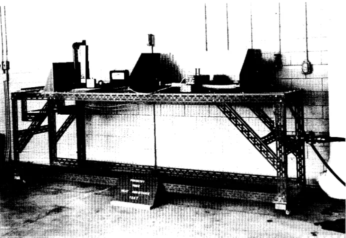
h o l d i n g t h e specimen d u r i n g a t e s t , and Fig. 5 shows t h e
whole i n use.
A
second a p p a r a t u s
i sused f o r t h e h e a t - r e s i s t a n o e
t e s t of hose.
The pump on t h e p r e s s u r e t e s t a p p a r a t u s
s u p p l i e s h i g h p r e s s u r e w a t e r t o b o t h apparatuses.
The
arrangement
i sshown i n Figs.
6 and
7 .
DETAILS OF PRESSURE AFPARATUS
Three c l e a r p l a s t i c t u b e s , 50 i n . long, 1 2 i n .
ODand
&
i n . i n w a l l t h i c k n e s s a r e mounted i n l i n e on a Dexion
framework.
As l o t c u t i n t h e bottom of t h e two end s e c t i o n s
allows leakage above t h e s l o t t o be c o l l e c t e d .
The d i s t a n c e
between t h e two s l o t s
i s1 0
f t .IChree troughs a r e provided,
two beneath t h e s l o t s , and one a t t h e bottom end of t h e tube.
A
modified three-may valve
i s employed a t each trough t o
permit t h e c o l l e c t i o n of leakage i n a graduate c y l i n d e r , o r
t o a l l o w
it t o flow back t o t h e r e s e r v o i r .
The r e s e r v o i r s u p p l i e s w a t e r t o a n a i r - d r i v e n
p i s t o n pump through a f i l t e r .
The d e l i v e r y of t h e pump t h e n
flows t o a n
accumulatort h a t cushions p r e s s u r e surges above
i t s
preload p r e s s u r e , which
i ss e t a t 250 p s i .
Aneedle
valve c o n t r o l s t h e flow from
t h i ssystem t o t h e specimen.
A t e e connection a f t e r t h e n e e d l e valve p r o v i d e s
a
p r e s s u r et a p a s w e l l a s t h e supply t o t h e specimen. A i r supply t o t h e pump comes from a 100-psi l i n e through a r e d u c i n g v a l v e , a w a t e r t r a p and a n o i l bubbler. An exhaust m u f f l e r completes t h e a i r - f l o w p o r t i o n of t h e system.
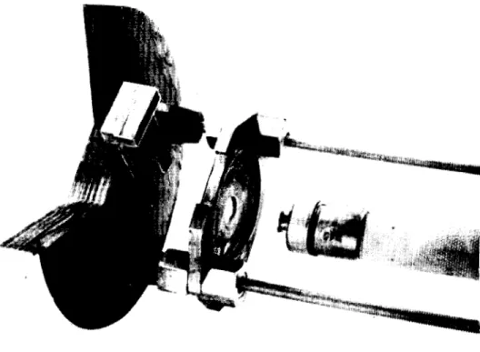
When a hose r u p t u r e s , t h e r e i s a chance t h a t t h e c o u p l i n g s , u n l e s s r e s t r a i n e d , w i l l s t r i k e and damage t h e p l a s t i c t u b e . To p r e v e n t t h i s , each c o u p l i n g i s a t t a c h e d t o a h o l d e r designed t o s l i d e on two b r a s s r o d s running t h e l e n g t h of t h e t u b e ; a t each end t h e r o d s a r e b o l t e d t o sub- s t a n t i a l wooden end-covers. One h o l d e r i s f r e e t o s l i d e
a s
t h e hose specimen e l o n g a t e s w i t h p r e s s u r e ; t h e o t h e r can be moved i f n e c e s s a r y t o accommodate specimens of v a r y i n g l e n g t h s . \When a specimen r u p t u r e s v i o l e n t l y , t h e main impact
i s
absorbed by t h e wooden p l a t e s and t h e b r a s s rods. A specimen i s f e d i n t o t h e tube from t h e t o p end of t h e tube and p u l l e d down by a nylon cord. The t o p end of t h e specimen i s t h e n f a s t e n e d t o t h e h o l d e r , and t h e supply hose connection i s made. The bottom end i s t h e n p u t i n t h e bottom h o l d e r . A c h a r t i s placed on t h e r e c o r d e r w i t h t h e a p p r o p r i a t e p r e s s u r e - t i m e curve drawn on t h e c h a r t . Flow i s manually c o n t r o l l e d w i t h b o t h t h e r e d u c i n g valve and t h e n e e d l e valve t o b r i n g t h e p r e s s u r e t o t h e value r e q u i r e d by t h e curve. When t h e f l o wi s s m a l l , p u l s a t i o n can be minimized by c o n s t r i c t i n g f l o w a t t h e n e e d l e v a l v e , while compensating f o r t h e consequent
p r e s s u r e l o s s a c r o s s t h e n e e d l e valve by r a i s i n g t h e r e d u c i n g valve s e t t i n g . With r a p i d flow, p u l s a t i o n i s n o t a problem.
The t o p and bottom h o l d e r s shown i n Figs. 3 and 4
a r e f o r l a - i n . hose. Other h o l d e r s have been made t o allom f o r t e s t i n g of 1 - i n . and &-in. hose.
LIST OF EQUIETIIEET USED
A i r pump
-
Sprague t y p e S-216C-20 Accumulator-
Greer model 30-A-1VS Dexion frameworkHose
-
Aeroquip h i g h p r e s s u r e type 1325 Recorder-
B a i l e y type Kh155A, 0 t o 300 p s i ,0 t o 1500 p s i
C l e a r p l a s t i c t u b e
-
Three s e c t i o n s 50- by 12-in. OD by &-in. w a l l , coupled w i t h D r e s s e r c o u p l i n g sValves
-
High p r e s s u r e needle v a l v e , Air-reducing valveF i l t e r s
-
A i r f i l - t e x t o remove w a t e r , S u c t i o n f i l t e r , 100 mesh, t o remove d i r t from w a t e r s u p p l y Gauges-
0 t o 3000 p s iD ~ A I L S OF HEAT RESISTANCE A ~ ~ A R A T U S
The Dexion framework provides a working s u r f a c e which i s undamaged by water, A s t e e l b l o c k 3 by 3 by 12 i n . , weighing a b o u t 32 l b , r e s t s on s t r i p s of a s b e s t o s while
it
i s h e a t e d . !bo Meker b u r n e r s f u e l l e d w i t h propane a r e used t o h e a t t h e s t e e l block, The temperature of t h e s t e e l b l o c k , which i s i n s u l a t e d by a s b e s t o s s t r i p s on t h e s i d e s , ends and t o p , i s measured by two thermocouples peened i n t o t h e t o p of t h e b l o c k and connected i n p a r a l l e l , Temperature r e a d i n g s a r e made w i t h a pyrometer. A f t e r removing t h e b u r n e r s , f i v e min i s allowed f o r t h e b l o c k t o a t t a i n thermal e q u i l i b r i u m b e f o r e it i s a p p l i e d t o t h e hose specimen.
Water i s s u p p l i e d t o t h e specimen by a l & - i n . hose connected t o t h e main supply. A $-turn v a l v e i s used t o t u r n t h e flow on o r o f f , a needle valve r e g u l a t e s
it,
and a r o t a - meter measures it. A p i e c e of l & - i n . hose i s used a s af l e x i b l e c o u p l i n g t o accommodate e l o n g a t i o n of t h e specimens under p r e s s u r e . A t e e permits a hose connection t o t h e h i g h p r e s s u r e supply from t h e p r e s s u r e - t e s t a p p a r a t u s . The
specimen i s coupled t o t h e a p p a r a t u s and r e s t s on a s m a l l t a b l e , which i s s h i e l d e d t o check t h e w a t e r s p r a y when a specimen r u p t u r e s .
LIST
OF EQUIIIVIENT USEDS t e e l b l o c k
-
3 by 3 by 12 i n . , i n s u l a t e d w i t h a s b e s t o sDexion framework
Gauges
-
0 t o 300 p s iValves
-
two $-turn v a l v e s l & - i n . s i z e , one n e e d l e valveRotameter
-
Brooks model F01112, 25 gpm c a p a c i t y Pyrometer-
B r i s t o l p o r t a b l e , Type No. 622,c a l i b r a t e d i n OF. Burners
-
P i s h e r c a t . No. 3-9022 Miscellaneous-
s h e e t metal s h i e l d s-
a s b e s t o s i n s u l a t i n g s t r i p s-
f l e x i b l e hose c o n n e c t i o n M r . E. 0. Porteous c o n s t r u c t e d t h e p r e s s u r e t e s t a p p a r a t u s i n i t s o r i g i n a l form and a s s i s t e d w i t h t h e d e s i g n .r W A T E R FILTER FAIR ACCUMULATOR AIR SUPPLY 100 PSI -"" L 7
I
PRESSURE REDUCING CONTROL VALVE TO HOSE SPECIMEN TO RECORDER SURGE" ACCUMULATOR L 0 - 3 0 0 0 -250 TO 3000 PSI HYDRAULIC ACCUMULATOR PSI GAUGETEST SPECIMEN FROM PUMP
L L 1
0 RETURN TO RESERVOIR
FIGURE
I
FLOW CHART OF PRESSURE AND LEAKAGE TEST APPARATUS
AIR C O N T R O L V A L V E T O P U M P AIR F I L T E R -\
\
k5lvREcoRDER
T R O U G H FOR M E A S U R E M E N C O N T R O L M E A S U R E M E N T S L Y D R A u L l c ACCUMULATOR AIR AIR/ I
# F I L T E R ACCUMULATORINPUT
ACCUMULATOR P U M PFigure