87 PFC/RR-12
/I
DOE/PC-70512-7
Development and Test
an Internally Cooled, Cabled Superconductor (ICCS) for Large Scale MHD Magnets
Semiannual Progress Report
Period from July 1, 1985 to December 31, 1985 Hatch, A.M., Marston, P.G., Tarrh, J.M., Becker, H., Dawson, A.M., Minervini, J.V.
Plasma Fusion Center
Massachusetts Institute of Technology Cambridge, Massachusetts 02139, USA
This work was supported by the U.S. Department of Energy, Pittsburgh Energy Technology Center, Pittsburgh, PA 15236 under Contract No. DE-AC22-84PC70512. Reproduction, translation, publication, use and disposal, in whole or part, by or for the United States Government is permitted.
NOTICE
This report was prepared as an account of work by an agency of the United States Government. Neither the United States Government nor any agency thereof, nor any of their employees, makes any warranty, express or implied, or assumes any legal liability or responsibility for the accuracy, completeness, or usefulness of any information, appara-tus, product, or process disclosed, or represents that its use would not infringe privately owned rights. Reference herein to any specific commercial product, process, or service by trademark, manufacturer, or otherwise, does not necessarily constitute or imply its en-dorsement, recommendation, or favoring by the United States Government or any agency thereof. The views and opinions of authors expressed herein do not necessarily state or reflect those of the United States Government or any agency thereof.
TABLE OF CONTENTS Section 1.0 2.0 3.0 4.0 4.1 4.1.1 4.1.2 4.1.3 4.1.4 4.1.5 4.2 4.2.1 4.2.2 4.2.3 4.2.4 5.0 6.0 iii Title Introduction
Review of Technical Progress Prior to July 1, 1985
Summary of Technical Progress, July 1 to December 31, 1985 Results of Design and Analysis Effort (Task I and II)
Magnet Preconceptual Design
Clamp Plates to Support Winding During Assembly Cooling Plates to Reduce Heat Leakage into Winding Arrangement for Leads and Splices
Weight Estimates
Choice Between Alternative Designs Analysis
Maximum Field in Winding Inductance and Stored Energy Stress in Longitudinal Structure
Pressure Drop and Friction Heating in Coolant Circuit References List of Symbols Page No. 1 2 4 4 4 4 6 6 8 9 9 9 9 10 12 14 15
List of Figures
Title
Sketch, Cross Section of Magnet Winding and Supporting Structure in Straight Portion.
Sketch, Showing Arrangement for Leads and Splices in Region of End Turns
Electrical and Coolant Flow Diagram, Magnet Winding Number 1. 2. 3. Page No. 5 7 13
1.0 Introduction
A three-year program to develop and test an internally-cooled cabled superconductor
(ICCS) for large-scale MHD magnets is being conducted by MIT for the Pittsburgh Energy Technology Center (PETC) under Contract DE-AC22-84PC70512. The program consists of the following four tasks:
I. Design Requirements Definition II. Analysis
III. Experiment
IV. Full-Scale Test
This report summarizes the technical progress on Tasks I and II during the period from July 1, 1985 to December 31, 1985. Progress in the period from January 1, 1985 to
June 30, 1985 is described in the Technical Progress Report dated November 1, 1985.
The objective of Task I is to establish the design requirements definition for full-scale conductors for use in early commercial MHD magnets. Since the focus of MHD power train development is fixed now on relatively small systems such as may be used in retrofit
applications, the work concerns conductors suitable for systems of that size and type.
The objective of Task II is to accomplish the analysis required to substantiate the design for the full-scale conductor, and to provide the background for defining an experi-mental test program (Tasks III and IV).
The program is directed specifically toward the development of ICCS because this type of conductor has many significant advantages over bath-cooled conductors for the MHD application: relatively higher stability margin, greater electrical integrity (because the conductor can be wrapped with continuous insulation), greater mechanical integrity and durability, and the elimination of a heavy-walled liquid helium containment vessel. The concept offers great promise in resolving the issues of constructability and long-term durability for commercial MHD magnets while minimizing the overall costs and risks of such systems.
In order to establish a conductor Design Requirements Definition, it is necessary to
know the design characteristics of the magnet in which the conductor is intended to operate. Since a suitable reference design for a retrofit-size MHD magnet did not exist when the
program was started, the development of a preconceptual design for such a magnet has been a major part of the Task I effort.
2.0 Review of Technical Progress Prior to July 1, 1985
A brief review of technical progress from the start of the program through June 30, 1985 is provided below as a background for the report of progress contained in Sections 3.0 and 4.0.
As a starting point for preconceptual magnet design, it was assumed that the typical retrofit-size MHD magnet will:
a. accommodate a supersonic MHD channel of about 35 MWe output, requiring a peak on:axis field of 4.5 T.
b. operate at a design current in the neighborhood of 25 kA.
As a baseline for conductor design, it was assumed that the dimensions and construc-tion of the conductor would be the same as of those of the ICCS conductor used in the large D-shape magnet designed and built by Westinghouse for the fusion Large Coil Program (LCP), described in Reference 2. This was done to take advantage of the manufacturing technology that had been developed for that project. The MHD conductor will, however, use niobium titanium (NbTi) superconductor rather than niobium tin (Nb3Sn).
The selection of magnet size and field strength is supported by information obtained from the MHD community as reported previously'. The selection of a relatively high design current is in the interest of minimum overall system cost, based on information provided in Reference 3. The selection of the particular ICCS overall dimensions and construction is aimed at minimizing conductor development time and cost by using a conductor size and construction for which production and tooling experience already exist.
An initial preconceptual design for a retrofit-size magnet was generated, incorporating a 600 rectangular saddle-coil winding of ICCS, without substructure, operating at a design current of 24 kA and surrounded by a stainless-steel force containment structure and cryostat.
A detailed computer analysis of the winding showed maximum fields to be
requiring that the design be modified to reduce the maximum field and assure stable op-eration.
Several winding design modifications, aimed at reducing the maximum field, were then analyzed. Modifications included changing the shape of the end turns, changing the aspect ratio of the winding cross section, and decreasing the winding average current density. A reduction of maximum field to below 6.9 T was found to be possible. A revised winding design having an increased thickness, an increased bend radius in the end turns, and a lower current density was established as most suitable for the application. Characteristics of the revised design and also of the original design are given below:
Coil Thickness (m)
Minimum End Turn Bend Radius (m)
Winding Average Current Density (A/cm2)
Design Current in Conductor (kA) Maximum Field in Winding (T)
Original 0.24 0.15 3900 24 7.2 (Orig. est 6.0) Revised 0.305 0.30 3200 18 6.9 3
The end product of the work was an improved magnet preconceptual design which compared favorably with earlier magnet designs in reliability, manufacturability, and cost-effectiveness, together with a draft Design Requirements Definition for the conductor that represents a sound basis for continued development and proof-testing of subscale conductor elements as well as a full-scale conductor prototype.
3.0 Summary of Technical Progress, July 1, 1985 to December 31, 1985
The magnet preconceptual design was reviewed, improved and developed in more detail. Estimates of stresses and component weights were reviewed. Results of electromag-netic analysis were reviewed and checked using alternative approaches. Pressure drop and friction heating in the conductor coolant circuit, arrived at by earlier analyses, were checked and found to be consistent with previous results. Accomplishment of this work provided a firm basis for establishing conductor design requirements and defining the experimental test program to be performed.
4.0 Results of Design and Analysis Effort (Tasks I and II)
The results of the design and analysis effort on magnet and conductor during the period July 1, 1985 to December 31, 1985 are described in more detail below:
4.1 Magnet Preconceptual Design
The magnet design was reviewed and developed in more detail.
4.1.1 Clamp Plates to Support Winding During Assembly
A means of securing the winding to the coil-form during assembly was designed and
is illustrated in cross-section sketch, Fig. 1. The six quadruple pancakes of each coil are assembled on the coil-form and clamped tightly to it by the clamp plates and side plates shown. The plates prevent the pancakes of the first winding-half assembled from dropping
away when the coil-form is rotated 1800 in preparation for assembly of the second winding-half. After both winding-halves are in place and secured by clamp and side plates the cover plates (part of the main longitudinal structure) are installed and then the beams
The Libraries
Massachusetts Institute of Technology Cambridge, Massachusetts 02139 Institute Archives and Special Collections
Room 14N-118 (617) 253-5688
There is no text material missing here. Pages have been incorrectly numbered.
and tension rods (which constitute the main transverse structure.) The cover plates, beams and tension rods are shown in phantom in Fig. 1.
4.1.2 Cooling Plates to Reduce Heat Leakage into Winding
A means of reducing heat leakage into the windings was designed and is also shown
in Fig. 1. This consists of a copper cooling plate interposed between the coil and the coil-form and cooled by helium tracer tubes. The plate will intercept heat that would otherwise flow from the coil-form into the windings and therefore reduces the amount of coolant flow required in the conductor itself during steady-state operation. Lowering the coolant flow in the conductor is beneficial because it reduces pumping losses. This feature is conceptual and requires further investigation to verify thickness of plate, etc.
4.1.3 Arrangement for Leads and Splices
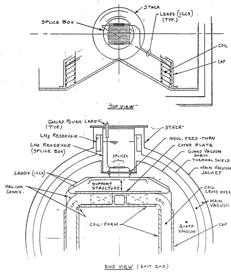
An arrangement for bringing out leads from each quadruple pancake, for separately cooling splices and for making helium connections, was designed and is illustrated in sketch, Fig. 2. In the end-turn region shown, the winding is curved in a circular arc in the portion between the 600 riser bundle and the crossover bundle. These curved portions are self-supporting against outward-acting magnetic forces. Supporting structure is not provided at either the outer or inner surface of these bends. Therefore, the bend regions are at a convenient place to make electrical and coolant connections. Each quadruple pancake is made of a single length of internally cooled cabled conductor, with ends extending well beyond the pancake (3 to 4 meter extensions). Coolant connections are installed in the cable at the three internal pancake-to-pancake transitions, located so that they are accessible at inside and outside of a bend. The bend selected for connections is that bend which is located at the top of the magnet at the exit end. A single large stack is located at the top of the magnet at the exit end above the winding end-turns. The extended cable-ends (leads) from each quadruple pancake are brought out at the open bend, worked back toward top center above the cover plate and main supporting structure and then carried up into the stack and splice-box through insulated feed-throughs. The splice-box is filled with saturated liquid helium at approximately 1.2 atm. pressure, so that the splices are cooled by boiling helium.
6PLICE. 150
- O L
jA. , vi .. L -A p
("-y P.) -- - Y
-ULN FESER\/01P\ -M5UL. FEE-) -TH RV
LHd REERUVO COYER P-rT-L (PLi.e SF ) GL)Psp \I-CUvm SPLICES 5HF-'U-TRE-xmP,1 SKIE LP A P-I N \ AU M HO .L5r (1 -L J A'A EX -C COIL VA CLU I I
COIL- FORM P &~e
Figure 2: Sketch Showing Arrangement for Leads and Splices in the Region of the End Turns
7
-V I
e-W.4.1.4 Weight Estimates
A review was made of magnet weight estimates. Alternative magnet designs had been
developed, differing in thickness of plate used in the internal structure (coil-form, cover plates, etc.) and hence having slightly different component and total weights, as listed below:
Conductor Insulation
Coil Form and End Plates Cover Plates
Clamp and Side Plates Caps
Beams and Tension Rods Guard Vacuum Shell Other (cold stack, et c) Thermal Shield Vacuum Jacket Magnet Total Weight Design A 47 5 39 12 9 6 53 24 10 15 100 320 (tonnes) Design B 47 5 52 15 6 7 53 32 10 15 100 342
These weights were found to be consistent with design characteristics. It should be noted that the total magnet weight of 320 tonnes listed in Progress Report, Reference 2, is in accordance with Design A above. It should also be noted that the design stresses in longitudinal structure, listed in the Analysis Report, Reference 3 are consistent with Design B.
4.1.5 Choice Between Alternative Designs
A further review of the design of the core-tube and associated structure indicates that
the strength of these components in Design A is adequate and that design is preferred because of its lower total weight. A discussion of longitudinal stresses in the core-tube and associated structural members is contained in Section 4.2.1 herein.
4.2 Analysis
Magnet system and conductor analyses that were performed in the preceeding period were reviewed, including electromagnetic analysis, thermodynamic analysis and structural analysis.
4.2.1 Maximum Field in Winding
The determination of maximum field in the winding was rechecked by several alterna-tive methods, because it is a critical factor in the overall design. Detailed three-dimensional computer calculations on the chosen design indicated a maximum field in the winding of
6.92 T.
4.2.2 Inductance and Stored Energy
The inductance and stored energy were calculated using the method described on page
105 of Reference 4. Entering ratios a and 3 (1.42 and 0.96) in the curves shown in Fig.
2.102 of Reference 4, the normalized inductance, L/(pz0
eN
2)
is found to be 0.52. Takingnumber of turns, N = 672, f = 10.3 m and p, = 47r x 10-7 we determine that inductance, L = 0.515 p~fN2 = 3.009 henries. Taking design current, I = 18,000 A, we determine that
stored magnetic energy, E = 0.5 LI 2 = 487 MJ.
4.2.3 Stress in Longitudinal Structure
The structural design and stress in the coil-form and associated longitudinal structural elements were reviewed (see Fig. 6 of Reference 3). Alternative designs examined were similar in configuration but different in wall thickness (cross section in plane of peak on-axis field) as shown below:
Structural Element Design A
Wall Section Thickness Area cm cm2 Design B Wall Section Thickness Area cm cm2 Coil Form 3.81 2419 6.35 4031 Cover plates 3.18 1129 3.81 1355
Guard Vacuum Shell 1.91 2642 1.27 1761
Conductor Sheath 0.165 922 0.165 922
(672 Conductors)
Total - 7112 - 8069
With a total longitudinal tension force (x-direction) of 4136 tonnes, the calculated stresses in the structural elements are given below for various assumed load distributions:
Assumed Condition
Load Distributed on All Elements Load Carried by Coil Form
and Guard Vacuum Shell Load Carried by Coil Form Alone
Load Carried by Guard Vacuum Shell Only
Stress Design A 56.8 80.0 167.3 153.2 (MPa) Design B 50.1 69.9 100.4 229.9
All the above elements are of 304 LN stainless steel operating at 4.5 K, at which
temperature the maximum allowable design stress is 414 MPa (see Table II, Reference 3). Therefore, the stresses in the structural elements as listed above are considered conserva-tive.
The coil-form wall thicknesses are greater than would be necessary for tensile loading only, because they are selected to withstand inward pressure loading and bending due to winding precompression, without being overstressed or deflecting excessively. A simpli-fied analysis to determine approximate behavior of the coil-form under external pressure
follows.
Assume the coil-form is a duct 2.1 m square with walls of uniform thickness externally loaded by 1 atm. pressure (vacuum inside). Bending stress and deflection calculated by simple beam theory are as follows:
Design A Design B
Coil Form Thickness (cm) 3.81 6.35
Max. Bending Stress (MPa) 155 56
Max. Deflection (cm) 0.59 0.13
The stresses and deflections shown above are moderate and considered acceptable for Design A and quite conservative for Design B. It has been taken into account that pressure loading could be at room temperature (prior to magnet cooldown) at which condition maximum design stress would be only 184 MPa. However, if winding precompression loading achieved by prestressing the tension rods is added to the 1 atm pressure load, then stresses and deflections would become excessive, particularly in Design A. It was decided that prestressing the winding via the tension rods was not necessary for this type of winding. Another means of preloading, such as a midspan beam-to-coil-form tie-rod could be employed. Therefore, it was considered that Design A was adequate. This matter should be further investigated when the preconceptual design is carried into the next (prototype) design stage.
4.2.4 Pressure Drop and Friction Heating in Coolant Circuit
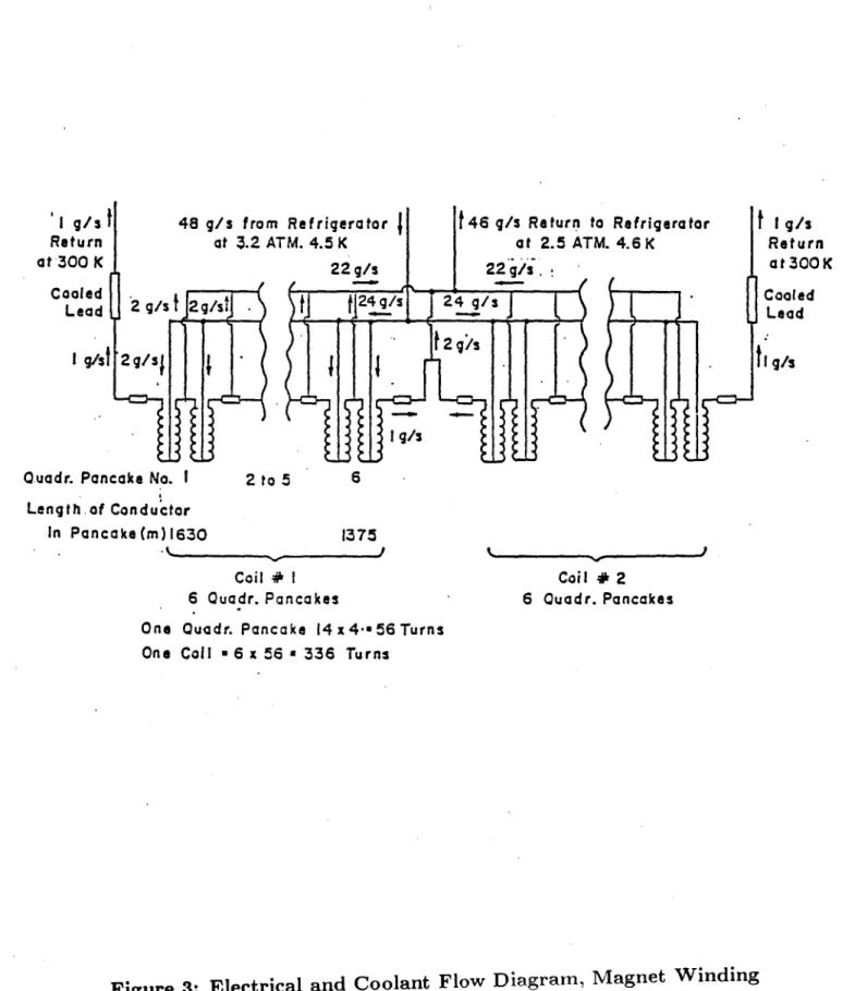
Pressure drop and friction heating in the coolant circuit of the windings was reviewed. The flow diagram, Fig. 3, shows coolant flow rates, temperatures and pressures in the magnet winding. Pressure drop and pumping power are calculated as follows:
Conductor length, L, single pancake (maximum)408 m
Mass flow rate 1 g/s
Density, p, at 3.2 atm, 4.5 K 0.13 g/cm3
Volume flow rate, v 7.7 cm3/s
Conductor void area 0.89 cm2
Flow velocity, V 8.65 cm/s
Reynolds number, R. 1500
Friction factor:
f 1 2
.7 + O698 + 0.0146 = 0.0343
Assume 25 W enter the winding through conduction and radiation from surroundings.
Total heat into winding - 50 W
Total flow rate through winding - 48 g/s
Heat flow into coolant = -= 1.04 J/g
Temperature rise of coolant 2 0.1 K Exit pressure of coolant a 2.5 atm
I g/s 1 48 g/s fron Return at 3.2 A at 300 K Cooled Lead 2 g/s 2g/si . I g/'sl 2g/s
Quadr. Pancake No. I
m Refrigerator TM. 4.5 K 22 g/s 24g/s g 2 to 5 at 2.5 ATM. 4.6 K 22 g/s 24 g/s 2 g/s s 6 Length.of Conductor In Pancake (m)1630 1375 Coil # I 6 Quadr. Pancakes Coil # 2 6 Ouadr. Pancakes One Quadr. Pancake 14 x4-m56 Turns
One Coil - 6 x 56 a 336 Turns
Figure 3: Electrical and Coolant Flow Diagram, Magnet Winding
13 i g/s Return at 300 K Cooled Lead
h 9/A
The results of the calculations shown above indicate that pressure drop and friction heating in the preconceptual design magnet winding will be within reasonable limits, pro-vided the heat leakage into the winding from the surroundings remains at or below the (conservatively estimated) level of 25 W.
5.0 References
1. Quarterly Progress Report, Oct. 1, 1984 to Dec. 31, 1984, Develop and Test an ICCS
for Large Scale MHD Magnets, MIT, March 1985 DOE/PC-70512-2.
2. Technical Progress Report, period from Jan. 1, 1985 to June 30, 1985, Develop and Test an ICCS for Large Scale MHD Magnets, MIT, November 1985, DOE/PC-70512-4.
3. Analysis Report, Develop and Test an Internally Cooled Cabled Superconductor
(ICCS) for Large Scale MHD Magnets, MIT, January 1986, DOE/PC-70512-5.
4. Thome, R.J. and Tarrh, J.M., MHD and Fusion Magnets: Field and Force Design
6.0 List of Symbols
A amperes
kA kiloampere (10' A)
MA megampere (106 A)
T tesla (106 gauss), magnetic field
m meter(s)
cm centimeters(s)
g gram(s)
kg kilogram(s) (103 g)
K degrees Kelvin
TUS tensile ultimate strength
TYS tensile yield strength
psi pounds per square inch
Pa pascal (1 newton/square meter)
MPa megapascals (106 Pa)
tonne metric ton (103 kg)
in inch lb pound N newton s second(s) W watts(s) ohm R resistance, electrical DC direct current L inductance, electrical V volt Cu copper J joule mJ millijoule (10-3 J) Nb3Sn niobium tin
NbTi niobium titanium
MHD magnetohydrodynamic
ICCS internally cooled, cabled superconductor
a- stress p pressure atm atmosphere(s) current, electrical IC critical current H enthalpy (thermodynamic)