HAL Id: hal-03215585
https://hal.archives-ouvertes.fr/hal-03215585
Submitted on 3 May 2021HAL is a multi-disciplinary open access
archive for the deposit and dissemination of sci-entific research documents, whether they are pub-lished or not. The documents may come from teaching and research institutions in France or abroad, or from public or private research centers.
L’archive ouverte pluridisciplinaire HAL, est destinée au dépôt et à la diffusion de documents scientifiques de niveau recherche, publiés ou non, émanant des établissements d’enseignement et de recherche français ou étrangers, des laboratoires publics ou privés.
Integration and Early Testing of WEAVE: The
next-generation spectroscopy facility for the William
Herschel Telescope
Gavin Dalton, Scott Trager, Don Carlos Abrams, Piercarlo Bonifacio, Alfonso
Aguerri, Antonella Vallenari, Georgia Bishop, Kevin Middleton, Chris Benn,
Kevin Dee, et al.
To cite this version:
Gavin Dalton, Scott Trager, Don Carlos Abrams, Piercarlo Bonifacio, Alfonso Aguerri, et al.. Inte-gration and Early Testing of WEAVE: The next-generation spectroscopy facility for the William Her-schel Telescope. SPIE Astronomical Telescopes + Instrumentation„ Dec 2020, Online Only, France. �10.1117/12.2561067�. �hal-03215585�
Integration and Early Testing of WEAVE: The next-generation
spectroscopy facility for the William Herschel Telescope
Gavin Dalton
*a,b, Scott Trager
c, Don Carlos Abrams
d, Piercarlo Bonifacio
f, J. Alfonso L. Aguerri
g,
Antonella Vallenari
n, Georgia Bishop
a, Kevin Middleton
a, Chris Benn
d, Kevin Dee
d, Shan Mignot
f,
Ian Lewis
b, Johannes Pragt
i, Sergio Pico
d, Nic Walton
j,
Juerg Rey
d, Carlos Allende Prieto
g, Emilie
Lhome
d, Marc Balcells
d, David Terrett
a, Matthew Brock
b, Andy Ridings
d, Marc Verheijen
c, Iain
Steele
e, Remko Stuik
i, Gabby Kroes
i, Neils Tromp
i, Jan Kragt
i, Dirk Lesman
i, Chris Mottram
e,
Stuart Bates
e, Frank Gribbin
d, Jose Alonso Burgal
g, José Miguel Herreros
g, José Miguel Delgado
g,
Carlos Martin
d, Diego Cano
d, Ramon Navarro
i, Mike Irwin
j, Luis Peralta de Arriba
j, Neil
O’Mahony
d, Andrea Bianco
l, Alireza Molaeinezhad
b,g,j, Rik ter Horst
i, Emilio Molinari
m, Marcello
Lodi
m, José Guerra
m, Andrea Baruffolo
n, Esperanza Carrasco
o, Szigfrid Farcas
k, Ellen Schallig
b,
Sarah Hughes
b, Vanessa Hill
p, Dan Smith
q, Janet Drew
q, Bianca Poggianti
n, Angela Iovino
n, Mat
Pieri
r, Shoko Jin
a,b,c, Lillian Dominguez Palmero
d, Cecilia Fariña
d, Adrian Martín
m, Clare Worley
j,
David Murphy
j, Steve Guest
a, Huw Morris
a, Eddy Elswijk
i, Menno de Haan
i, Hiddo Hanenburg
i,
Bernardo Salasnich
n, Divakara Mayya
o, Rafael Izazaga-Pérez
o, Emanuel Gafton
d, Elisabetta Caffau
f,
David Horville
f, Francisco Paz Chinchón
j, Jesus Falcón-Barosso
g, Boris Gänsicke
s, Jose San Juan
m,
Nauzet Hernandez
maRALSpace, STFC Rutherford Appleton Laboratory, OX11 0QX, UK; bDept. of Physics, University of Oxford, Keble
Road, Oxford, OX1 3RH, UK; cKapteyn Institut, Rijksuniversiteit Groningen, Postbus 800, NL-9700 AV Groningen,
Netherlands; dIsaac Newton Group, 38700 Santa Cruz de La Palma, Spain; eAstrophysics Research Institute, Liverpool
John Moores University, IC2 Liverpool Science Park, 146 Brownlow Hill, Liverpool, L3 5RF, UK; fGEPI, Observatoire
de Paris, Université PSL, Place Jules Janssen, 92195 Meudon, France; gInstituto de Astrofisica de Canarias, 38200 La
Laguna, TF, Spain; iNOVA ASTRON, PO Box 2, 7990 AA, Dwingeloo, Netherlands; jInstitute of Astronomy,
Madingley Road, Cambridge, CB3 0HA, UK; kKonkoly Observatory, H-1525 Budapest, P.O.Box 67, Hungary; lOsservatorio Astronomico di Brera, INAF, via E. Bianchi 46, 23807 Merate (LC), Italy; mFundación Galileo Galilei,
INAF, Rambla José Ana Fernández Pérez, 7, 38712 Breña Baja, TF, Spain; nOsservatorio Astronomico di Padova,
INAF, Vicolo Osservatorio 5, 35122, Padova, Italy; oINAOE, Luis Enrique Erro 1, Tonantzintla, Puebla, Mexico; pOCA; qUniversity of Hertfordshire, UK.; rLAM; sUniversity of Warwick, UK
ABSTRACT
We present an update on the overall integration progress of the WEAVE next-generation spectroscopy facility for the William Herschel Telescope (WHT), now scheduled for first light in early-2021, with almost all components now arrived at the observatory. We also present a summary of the current planning behind the 5-year initial phase of survey operations, and some detailed end-to-end science simulations that have been implemented to evaluate the final on-sky performance after data processing. WEAVE will provide optical ground-based follow up of ground-based (LOFAR) and space-based (Gaia) surveys. WEAVE is a multi-object and multi-IFU facility utilizing a new 2-degree prime focus field of view at the WHT, with a buffered pick-and-place positioner system hosting 1000 multi-object (MOS) fibres, 20 mini integral field units, or a single large IFU for each observation. The fibres are fed to a single (dual-beam) spectrograph, with total of 16k spectral pixels, located within the WHT GHRIL enclosure on the telescope Nasmyth platform, supporting observations at R~5000 over the full 370-1000nm wavelength range in a single exposure, or a high resolution mode with limited coverage in each arm at R~20000.
Keywords: Multi-Object Spectroscopy, Fibre Optics, High Resolution Spectroscopy
1. INTRODUCTION
The WEAVE[1,2] project began in early 2010 with a series of national meetings within the partner countries (The UK,
The Netherlands, and Spain) of the Isaac Newton Group of telescopes, aimed at developing a comprehensive strategy for the 4.2 William Herschel Telescope (WHT) for the next decade. These meetings identified the need for a dedicated high-multiplex spectroscopic facility to complement upcoming large-scale survey programs in Galactic and extra-Galactic astrophysics, particularly from new facilities such as ESA’s Gaia satellite [3] and the European Low Frequency Array
(LOFAR[4]). Gaia is already providing[5,6] an unprecedented picture of the structure and dynamics of the Milky Way from
measurements of precise positions and parallaxes for more than 109 objects with (V ≤ 20) over the whole sky, with still
more to come, but is unable to measure the radial component of velocity for the majority of the stars (V>16.5), and has limited spectroscopic capabilities that restrict chemical abundance measurements to only the brightest (V<12) stars in the survey. LOFAR’s ongoing surveys will detect more than 107 radio sources from high-resolution radio imaging at 30, 60,
120 and 200 MHz over 10000 square degrees of the Northern Sky, but the majority of these are continuum detections with no spectroscopic information to provide redshifts or information on the evolutionary state of the sources. APERTIF[7] will provide detailed information on the kinematics and dynamics of neutral hydrogen in galaxies at low and
intermediate redshifts (z~0.3), but complementary observations are required at visible wavelengths to connect these data with the stellar populations and star-formation activity.
WEAVE was initially developed as a joint project between the UK, Spain and the Netherlands, but the project has been open to wider participation, and the partnership now includes France, Italy, the Konkoly Observatory and INAOE. A number of other individuals and institutes have contributed to join the WEAVE science consortium but are not participating directly in the construction of the facility.
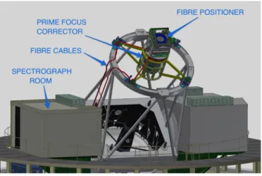
Figure 1: Illustration of the components of WEAVE showing the new top end structure and the route of the fibres to GHRIL. The final design of WEAVE was reported in 2016[8], and the aim here is not to repeat what has already been set out, but
rather to report on the progress towards realization of the design. Many of the WEAVE systems are now close to completion, but there have been some surprises and the inevitable delays along the way. Many of the design details of the individual systems have been reported previously in these proceedings[9-22], and so we aim here to focus on the
progress that has been realised in recent years, and a view of the updated schedule for first light: In Section 2 we cover the new prime focus infrastructure, Section 3 summarises the final status of the fibres themselves, while Section 4 addresses the WEAVE fibre positioning system. The as-built spectrograph is presented in Section 5, and Section 6 discusses the diverse components of the software infrastructure required to operate and exploit the WEAVE facility. Section 6 includes the description of a set of ongoing detailed operational simulations that are designed to test the end-to-end operation of the software infrastructure and validate the final scientific performance. We conclude with a summary of the overall project schedule to completion as it sits at the time of writing, an outline of science verification, and a brief overview of the science surveys that will occupy the first 5 years of WEAVE operations.
2. PRIME FOCUS ASSEMBLY
The original top-end structure of the WHT provided for a prime-focus instrument package, but was unable to accommodate the mass or the size required for WEAVE. After initial attempts to design a drop-in replacement for the original inner flip-ring structure, it was decided to remove this ring altogether, and mount a new set of spiders directly to the fixed outer ring of the structure. Focus and tilt adjustment of the top end is achieved by cam adjusters within the mounting points to the outer ring, referred to as the Focus Translation System (FTS) [23]. The centre-section located by
these spiders provides a 3-point mount for the wide-field corrector (PFC) and a mounting flange to support the instrument rotator unit (PFR), which in turn supports the fibre positioner. The design of the FTS units was modified to increase the stiffness of the interfaces, and the full system was shown to be within specification for stability on-telescope in July 2018.
The PFR was first delivered to La Palma in March 2019 but was returned to IDOM for rework of the mounting flange, and returned to the telescope in June 2019. Full details of the rotator can be found in ref [27].
Figure 2 (left) The PFR under test in the WHT dome. (right) The corrector installed in the top end and ready for testing on-sky.
The 6 lenses for the PFC were polished by Kiwistar Optics[9] and delivered to the IAC. The lenses were shipped to
SENER Aerospatiale for integration[10] in December 2018, and the completed corrector was delivered to La Palma in
June of 2020. The optical design of the corrector permitted assembly to be achieved by mechanical tolerances only, obviating the need for interferometric measurements during integration. Due to travel restrictions, final testing of the corrector at SENER and integration and alignment of the corrector to the top end structure, and on the telescope, have relied heavily on intensive remote presence of project staff via zoom, with remarkable success.
Performance of the ADC elements was verified using a 3-colour laser system, and the final optical performance verified on-sky with the telescope and a Shack-Hartmann camera mounted on a translation stage within the mass-dummy for the positioner system. The on-sky measurements were carried out in August through October of 2020, with the conclusion that the system delivers 80% encircled energy with 0.71”, corresponding to an image quality of 0.41” FWHM (both seeing deconvolved), which is in excellent agreement with the design analysis. Subsequent observations with a pair of imaging cameras mounted on-axis and close to the edge of the field suggested the presence of a residual tilt of the focal plane arising from a misalignment of the corrector axis to the rotator. This has now been adjusted on-telescope, and validatory measurements are now in progress.
3. FIBRES
WEAVE supports 3 distinct modes: 960 single fibres (MOS), 20 deployable 37-fibre mini integral field units (mIFU) and 1 monolithic (603-fibre) static integral field (LIFU). Two instances of the MOS mode exist in the positioner, to allow configuration of the next field to take place in parallel with the current observation, and so there are 4 fibre cable bundles[28] routed from the positioner through the rotator cable wrap, out along the spiders and down the telescope
structure to where the spectrograph is housed in GHRIL. Each of these ~36m cables is terminated at the spectrograph in a slit assembly with, respectively, 40, 40, 20 and 27 slitlets which are abutted to a field lens within their own slit unit. The input focal surface of the spectrograph is curved in two directions.
Figure 3: Rendering of the layout of a single MOS fibre bundle (lengths not to scale!)
The design of the fibre cables reflects the modularity of the system, in that a single slitlet of 24 fibres maps to a group of 4 retractors (6 fibres each) at the positioner, and cables for 4 slitlets are grouped together into a single conduit for routing through the prime focus cable-wrap and around the telescope structure. This cable of 96 fibres with 4 slitlets and 16 sets of 6 MOS fibres forms one deliverable unit. The first MOS cable was delivered to Oxford in August 2019 after testing in Paris. The final cable for MOS A was delivered in mid-March 2020, just as France entered the first full lockdown for Covid-19. Delivery of the MOS B cables commenced in mid-June 2020, together with the mIFUs, with the last cable arriving in Oxford the 1st week in August.
Figure 4: (left) Sorted rows of fibres being installed into one half of the LIFU head. (right) A view of the completed LIFU head after
The LIFU cable, terminated at one end with slitlets was delivered to NOVA in the summer of 2019 and sorted into rows according to a science-led prescription aimed at keeping adjacent fibres on the sky well-separated at the slit, and of spreading the fibres in the offset sky-sampling apertures evenly along the slit. These rows were then assembled into the two halves of the LIFU ‘head’ with an additional 3 fibre wide buffer annulus of unused short fibres to support the array. The head was then polished and installed behind its field lens within a unit that also houses an off-axis guide camera, and which mounts to the outside of the positioner tumbler structure (see below). The LIFU was delivered to Oxford at the end of June 2020.
The slit unit for the LIFU was assembled in Dwingeloo, prior to shipping to Oxford along with the integration bench, with the intent that the NOVA team would assemble the MOS and mIFU slits in Oxford once the fibres were installed in the positioner. Travel restrictions due to Covid-19 meant that this approach was impossible, and so the installation of these was carried out by the positioner team.
4. POSITIONER
The integration and testing of the positioner is described in detail in ref [29]. Each cable is packaged such that the fibres for each retractor are grouped separately. These were extracted, identified, and the inevitable tangles that had been introduced along the 2m length of the PEEK tubing were worked out by hand. The six buttons were then stowed on a small steel plate attached to a length of plastic trunking that was used to guide the fibres along the axis of the tumbler to where they can be collected, the steel plate removed from the trunking, and the group of buttons fed through one of the apertures in the side wall of the tumbler structure. There is sufficient length of PU tubing between the 1:4 breakout box and the 1:6 breakout box that the latter can be drawn out to a workbench next to the positioner. The 2m lengths of PEEK tubing were then installed into the retractor and the 1:6 breakout box forms the entry interface. The retractor unit was then tested by hand on the bench to ensure that all six channels were running freely, and the PU tube was drawn back through the tumbler structure and the retractor unit fixed in place. It was estimated that 1 hour should be sufficient for each retractor to be assembled with this process, although any issues that were encountered could increase this by up to a factor of 3 in the worst cases. Adequate preparation of the retractor and components was key to the ease of assembly, and on the plus side it did prove possible to install the final 12 retractors in a single day.
Figure 5: (left)The completed positioner in the lab. (upper right) A subset of the parked fibres for MOS B illustrating the tiered
arrangement of the retractors, 2 mIFU retractors can be seen interspersed with the MOS fibres, and one guide fibre button (bottom tier, 2nd fibre from the right) can be discerned. (lower right) A view of the field of MOS A ready for deployment with both robots in play.
The mIFU cables were installed in a very similar fashion, 2 units to each of 10 retractors. The mIFU retractors follow a similar design to the MOS, but with the notable exceptions that they are single-sided, there is only sufficient transverse space in the spare length box for a single PU-PU tube crossing (hence a shorter length within the retractor), and the spring tensioners on the lower-pulleys had to be doubled up with stronger springs (approximately 6x more spring force than the MOS) in order to overcome friction between the PU tube and the retractor casing.
The guide fibre bundles also required a slight modification to the MOS retractors in terms of a stronger spring (the same used for the mIFUs) and some additional space to allow free path of the fibre down from the top pulley. Again, the main issue here is friction between the outer sleeve (PEEK in this case) and the wall of the retractor unit. The assembly of the guide fibres into their retractors was complicated by the short available length of the coherent bundles used, and so they were assembled on the tumbler unit before other MOS fibres had been installed. On the MOS A side the guide fibres each inhabit a retractor of their own. On the MOS B side the other 5 slots are occupied by fibres that have been displaced by the mIFUs, and which would otherwise have been lost. This was achieved by installing 5 fibres into the retractor, moving back into the tumbler structure and then installing the guide fibre last. The final MOS fibre that would otherwise have been installed was coiled up inside the spare length box of this retractor, and is available to be swapped-in if desired. A consequence of this sharing of space between the MOS and guide fibres was that the first MOS cable installed into plate B maps to 8 different locations around the periphery of the field.
Once the fibre installation was complete, the two field plates were installed. The original plan was that the field plates would be machined from solid invar (stress-relieved) with a pocketed rear structure to achieve substantial light-weighting. These were manufactured in-house and sent for lapping, but subsequent metrology revealed a relaxation of the surface form in the ~3 months post-lapping. The process was repeated using solid plates, but yielded effectively the same results. It was therefore decided to artificially age the plates by temperature cycling through liquid nitrogen, and then re-machine by turning the surface on a lathe.
Initial calibration of these offsets, prior to shipping the positioner to La Palma, showed that it is possible to achieve a single move to place a fibre within 5µm of the desired target position. Iterative placement is implemented to allow the final position to be adjusted to tolerance as required. These offsets will be revisited post-shipping once any handling-induced movement of the tumbler relative to the robots has been accommodated.
Figure 6: (left) A subset of the upper tier fibres being deployed in a circle during calibration. (right) A single quadrant of a full field
deployed for software testing, illustrating the full 3-dimensional nature of the fibre crossings.
The final part of the positioning scheme is the calibration between the robots and the field plate itself. A grid of ~400 reference spots, 20mm pitch, was etched into the surface of each field plate and can be illuminated and imaged by the onboard camera. Each robot scans a subset of this grid at the start of each configuration to compensate for any movement
of the tumbler due to changes in zenith distance. A full scan of this grid with each robot is used to determine the straightness and perpendicularity of the robot axes. This configuration uses a direct optical path to the plate, rather than the folded path used to image the fibre core. Calibration of the precise (virtual) location of the centre of rotation on the CCD in this configuration (~32mm off-axis) is critical to ensure that both robots agree on the position of all fibres in the field, which we validate using a sparse grid of 25 fibres positioned on the plate and then measured in-situ by both robots. As a final stage in pre-shipping checks, we ran a quadrant of a test configuration through the full software system to follow the fibre moves. The software[30] keeps track of the order in which fibres have been placed in the field, and each
potential move is checked to ensure that only the upper fibre of any crossing pair can be moved. The software determines the next available move for each robot based on the current positions and planned move for both robots. As expected, the system used only a single robot to deploy the chosen quadrant (at this stage, 25 minutes for ~200 fibre moves), but was able to make efficient use of the second robot in returning the fibres to their parked positions.
5. SPECTROGRAPH
In August of 2018 the 5th lens for the red camera of the spectrograph suffered a catastrophic failure at INAOE (rapid
unscheduled disassembly) during the final phase of manufacture. This is one of 4 S-FPL51 lenses in the spectrograph, and it was immediately possible to repurpose the blue-arm element as a replacement to complete integration of the red camera while a replacement blank could be sourced. It was, however, found to be difficult to source a replacement blank for this material (298mm diameter x 67mm thick), with projected lead-time of more than 1 year, and some nervousness from Ohara as to the success rate of producing blanks of this size in this material, which has the combination of a relatively high CTE and very low thermal conductivity. Fortunately, Ohara were able to locate a single remaining blank from their last production run, but with a size of 390x125mm, which they were (understandably) unwilling to downsize. We were therefore able to secure this blank and arrange (with Hellma) to slice it diagonally to achieve a replacement for lens 5 and a suitable spare for future contingency. The reworked red lens 5 was completed in February 2019, and the sliced replacement blank was delivered to INAOE from NOVA at the end of April 2019, and the finished lens (the final lens for the spectrograph) delivered to NOVA at the end of July 2019. Mounting of the spectrograph optics was completed by mid-December.
Figure 7: (left) Lens groups of the red camera during integration. (center) The complete spectrograph under test in the lab
at ASTRON. (right) The spectrograph being lifted into the GHRIL enclosure.
Throughout the testing phase of the spectrograph we experienced issues with the reliability and noise performance of the detector system. Some of this was tracked to issues with older driver boards being used with INGs ULTRADAS system, but an investigation of the noise performance suggested that a redesign of the detector PCBs was in order. This was implemented by Simon Tulloch of QCAM. When the spectrograph was packed for shipping to La Palma the cryostats were therefore returned to LJMU for installation of the new boards, final installation of the science detectors, and a repair to a leak in the pipework for the LN2 tank in the red cryostat. It was discovered that some damage to the red
window had occurred during handling, and proposed to coat the spare window for replacement, but this was also damaged during removal from its location in the blue arm. Two new windows (one red, one spare) are now expected imminently for final installation. The blue cryostat installation and test was completed in time for this to join the positioner for shipping to La Palma.
6. SOFTWARE SYSTEMS
Integration of the prime focus system control elements (FTS, PFR, ADC) to the telescope control system is complete. Testing of the spectrograph and positioner control systems with the top-level instrument control have been completed at unit level. The full software suite for WEAVE begins with submission of catalogues for survey observations and manages the flow of data and observations through field configuration, scheduling[22] and management of
observations[21], quality control, data processing[31] and analysis and ends with a complete archive[32] that will be used to
manage visualization and staged releases of the data.
We have conducted a set of operational simulations[24], covering 3 full months of WEAVE observations selected from an
18 month window, to evaluate the performance of the software systems in terms of scheduling efficiency and final data quality. The simulations take template spectra for all observed targets, apply the geometry of the input beam from the telescope to the fibre in put at that location in the field, and trace the light through the ray-trace model of the spectrograph to the sampling of the detector pixels. Throughput, noise and sky background appropriate to the date, time and position of the observation are applied, together with seeing and atmospheric transmission from archived weather logs. The data ‘observed’ in this way are then passed to the processing chain for reduction and analysis, and then distributed back to the science team via the archive.
Figure 8: Organisational map of the operational rehearsal data flow showing interactions between the science teams, the submission
platform (WASP), the simulations (SIM) through the telescope and Observatory Control System (OCS) and to the elements of the data processing chain (CPS/APS) and the archive (WAS).
These simulations have proved invaluable in troubleshooting the interfaces and specifications required to make this complex system operate seamlessly, and in tuning the detailed designs of the surveys themselves to try to maximise the scientific output from the facility.
7. SUMMARY AND PROSPECTS
After some delays in shipping, due to the current global situation, the positioner has now reached the Canaries, and will hopefully be delivered to the observatory before the Christmas break. Check-out and integration to the top end will commence mid-January with final calibration of the positioner taking place in-situ. Integration of the detector cryostats to the spectrograph will dovetail into the first mounting of the full top-end to the telescope and installation of the fibre slits to the spectrograph. Actual first light is therefore expected to take place in February-March, with up to 50 nights expected for on-sky commissioning, including a weather allowance. First science data is therefore expected before mid-2021.
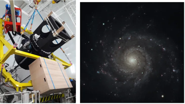
Figure 9: (left) The shape of things to come: top end with corrector, rotator and dummy positioner being installed on the telescope,
with boxes to show the space envelope of the transport boxes for the fibre cables and slit units. (right) A ‘first light’ image of M74 obtained on-axis during on-sky testing of the corrector system.
The 5-year survey programme for WEAVE is described in detail in ref [24], and was extensively and positively reviewed in January 2020. In parallel with the surveys, the remaining 30% of the WHT time is available for normal PI-mode observations, with an expectation that much of this time will also be allocated to WEAVE projects. These PI projects will have the benefit of the full data management infrastructure available to the surveys. The first full public data release of the 1st year of survey data is scheduled for 1 year after the last observation in that set is obtained.
ACKNOWLEDGMENTS
Funding for the WEAVE facility has been provided by UKRI STFC, by the University of Oxford, by NOVA, by NWO, by Instituto de Astrofísica de Canarias (IAC), by the Isaac Newton Group partners (STFC, NWO, and Spain, led by the IAC), by INAF, by CNRS-INSU, by the Observatoire de Paris, by Région Île-de-France, by Région Franche Comté, by Observatoire de Besançon, by ConaCyt through INOAE, by Konkoly Observatory of the Hungarian Academy of Sciences, by Max-Planck-Institut für Astronomie (MPIA Heidelberg), by Lund University, Uppsala University, AIP and the University of Pennsylvania. The WEAVE Survey Consortium consists of the ING, its three partners, represented by UKRI STFC, NWO, and the IAC, NOVA, INAF, GEPI, INAOE, and individual WEAVE Participants. The WEAVE website1 and the full list of granting agencies and grants supporting WEAVE2 are available from the project web pages.
Over the 10+ years of the WEAVE project it has been a great pleasure to benefit from discussions with colleagues in the field, many of which have been ‘hosted’ by the SPIE conferences. We have benefitted enormously from our interactions with our industrial partners at Kiwistar, Schunk, SENER Aerospatiale, IDOM, SEDI-ATI, KOSI, Fibertech Optica, AMS and Fiberguide. We are also particularly grateful to those who have been able to join us in various reviews of the project to contribute their insight and wisdom, and to take a fresh view of things.
REFERENCES
[1] Balcells, M., et al., Proc. SPIE 7735 (2010). [2] Dalton, G., et al., Proc. SPIE, 8466, 23 (2012). [3] Prusti, T. et al., EAS 45, 9 (2011).
[4] van Haarlem, M., EAS 15, 431 (2005). [5] Gaia Collaboration, A&A 595, A1 (2016) [6] Gaia Collaboration, arXiv 1804.09365 (2018)
[7] Oosterloo, T., et al., Proc. ISKAF Science Meeting (2010). [8] Dalton G., et al., Proc SPIE, 9908, 1G (2016)
[9] Bogunivic, D., et al., Proc SPIE, 10700, 118 (2018) [10] Tomàs, A., et al., Proc SPIE, 10706, 4 (2018) [11] Murga, G., et al., Proc SPIE, 10700, 235 (2018) [12] Delgado, J. M., et al., Proc SPIE, 10700, 33 (2018) [13] Schallig, E., et al., Proc SPIE, 10702, 7X, (2018) [14] Dalton, G. et al., Proc SPIE 9913, 2X (2016) [15] Rogers, K., et al., Proc SPIE, 9147, 6H (2014) [16] Izazaga, R., et al., Proc SPIE, 10706, 0J (2018) [17] Izazaga, R., et al., Proc SPIE, 10706, 3J (2018) [18] Bianco, A., et al., Proc SPIE, 10706, 4X (2018) [19] Bates, S., et al., Proc SPIE, 10709, 1Z (2018) [20] Salasnich, B., et al., Proc SPIE, 10707, 1X (2018) [21] Pico, S., et al., Proc SPIE, 10704, 2A (2018) [22] Fariña, C., et al., Proc SPIE, 10704, 0W (2018) [23] Casalta, J.M., et al., Proc SPIE, 9912, 200 (2016) [24] Jin, S., et al., MNRAS in preparation.
[25] Doel, P., et al. Proc SPIE, 8446, 6FD (2012) [26] Lewis, I. et al., Proc SPIE 9147, 34L (2014) [27] San Vincente, A. et al., Proc SPIE 11445, 4S (2020) [28] Mignot, S. et al., Proc SPIE 11450, 2F (2020) [29] Hughes, S., et al., Proc SPIE 11447, 7R (2020) [30] Terrett, D., et al., Proc SPIE 9152, 0P (2014) [31] Walton, N. et al., Proc SPIE 9152, 0R (2014) [32] Guerra, J. et al., Proc SPIE 9913, 1X (2016)
1https://ingconfluence.ing.iac.es:8444/confluence//display/WEAV/The+WEAVE+Project
2