Splitless Injection on Capillary Columns, Part II.
Conditions and Limits, Practical Realization
by K. Grob and G. Grob, Department of Organic Chemistry, University of Zurich, Switzerland
Abstract
Our procedure of direct splitless injection on capillary columns is based on the choice of column temperature for injection. Under appropriate conditions a marked concentra-tion effect is observed, i.e. the eluted band is more concen-trated than the injected one. The dependence of this effect on column temperature, injection time, sample size, and other variables has been studied experimentally. A solvent bypass-ing technique has been developed which allows the perform-ance of trace analysis on capillary columns.
Introduction
Part I (1) of this study reported a simple method of sample injection without stream splitting. Conditions and limits of this method were not discussed in detail. There is a strong belief in the rule that for analysis on capillary columns the liquid sample "should be in-troduced very sharply and evaporate instantaneously and completely" (2). Furthermore "a sharp sample plug," as produced by a properly designed stream splitter, should enter the column.
The maximum volume V, of the vapor plug in the injection port with negligible effect on column per-formance is (3)
V, V"„ V'n) 0.6
Under our experimental conditions n - 300,000, t,, 15 min ) V, is approximately 0.1 ml. The correspond-ing maximum injection time is of the order of 1 sec. According to our experience this ruk is correct for very short retention times and for isothermal analysis. For normal and longer retention, even onder isother-mal conditions, it is too severe. It no longer holds when during injection the column temperature is e.g., 50'C below analysis temperature. Whether heating from in-jection temperature to analysis temperature is done rapidly or slowly is of no importance. This means that a much larger sample with proportionally lower concentration can be introduced into the column with-out specially designed trapping and without subse-quent instantaneous vaporization.
As far as we know there is no theoretical treat-ment of the problem available. According to current opinion the sample plug concentrated on the cooled column should broaden during warming, thus making the intermediate reduction of the column temperature ineffective. In this paper we descrihe in detail our oh-servations as well as some application techniques de-veloped.
Apparatus and Materials
Most of the tests were run on a glans capillary of 0.35 mm, i.d., and 65 m length, coated with Emulphor
O ( polyethylene glycol octadecylether) . The separa-tion number of this column for the pair tridecane-tetradecane at 80°C and 6 ml H, per min was 52 (n = 260,000) . The chromatographic equipment including stream splitter was the same described in Part I of this study.
The samples were members of the n-2-alkanones series. For gaseous sampling we prepared a mixture of 0.1 g butanone, 0.2 g 2-pentanone, etc. up to 3.2 g 2-nonanone. The mixture was kept in a serum vial and gaseous samples were taken from the headspace with a common 10 pl syringe. Solutions of equal amounts of alkanones in hexane were prepared for liquid sam-pling. The concentration of single compounds in the different, solutions was 0.2%, 0.01%, 0.002% respec-tively.
Experimental
Gaseous Samples, Influence of Injection Time
We preferred gaseous samples to study the influ-ence of sample injection time to the column to elimin-ate the problem of excess solvent. A constant amount of headspace gas, taken at room temperature, was in-jected either rapidly or over a measured time period. To assure equality between the manually adjusted injection time and the duration of sample introduction into the column, we used constant stream splitting for all injections. It must be emphasized that the ob-ject of this splitting was not the usual one but was to eliminate diffusion of the sample in the injection port with corresponding prolonged sample input into the column.
Figure 1A shows the chromatogram of a regular run with rapid injection and constant column temper-ature. Increasing the injection time up to 20 sec led to chromatogram 1B which shows broadened peaks, especially for the more volatile sample components. It is interesting to note, however, that the base width of the octanone peak is in the order of 10 sec, i.e. half the injection time. Thus more than a twofold concen-tration takes place for this component even under iso-thermal conditions.
This concentration effect is increased when the column temperature is lowered for injection. A tem-perature reduction of 50° leads to a concentration sufficient for ideal resolution of those substances which
1. Grob, K. and Grob, G., J. Chromatog. Sci. 7, 584 (1969). 2. Ettre, L. S., "Open Tubular Columns in Gas
Chroma-tography," Plenum Press, New York, 1965, p. 112.
3. Littlewood, A. B., "Gas Chromatography" Academie Press, New York and London, 1962, p. 164.
31 5 2 sec 29 C4 5 2 sec c, Ce 2 4 Injectlon during 20 sec ot 25°C jLN1 75° 25° B injection dunng 20sec at 75 °C A injection during 05 sec at 75° C 57 sec (byproduct of solvent )'.. 10).110.01% solution injected without splitting, after 20 sec. splitting 1,20
C 1.011 001% solution no splitting at any time B C5 4 C8 c, A 0.2 nl 0.5% solution split ratio 110 C9 Ce
1
nsotn 75 °Figure 1. Column and chromatographic conditions see text. 2.0 p,I of gaseous 2-alkanone mixture (butanone to nonanone; headspace) injected with constant split ratio 1:10. Column temperature for injection and injection time varied.
30 c an' 25 a> E — 20 c 0 U a> •E 15 _ C4 10 peak width w 2 T I I i 2 3 4 5 6 7 8 9 10 11 (sec) Figure 2. 2.0 pl of gaseous alkanone mixture C4-C8. Column
temperature during injection 25', after injection temperature program 5°/min. Effect of varied injection time on width of single peaks.
show reasonable retention at the given temperature of 75° (i.e. heptanone and higher homologues ) ( Figure 1C.) More volatile samples are normally run at lower temperatures. These substances can also be well re-solved after lowering the column temperature for slow injection. The increased peak heights in Figure 1C as cornpared to 1A are due to decreased split ratio caused by decreased flow resistance at 25°C.
Figure 3. Liquid sample, alkanones C4-C8. Chromatographic
conditions as for Figure 2. A: Regular procedure. B-C: In-creased size of more dilute sample injected without splitting.
To improve the chromatographic conditions for the more volatile sample components, we used a tempera-ture program of 5° per min instead of heating rapidly from injection temperature to analysis temperature. For injection the column was held at 25°C as before, and the injection time was varied. From the chromato-grams obtained this way we determined the relation between injection time and peak width for all compo-nents (Figure 2). Nonanone showed constant peak shape for all injection times used and was therefore left out of the sample. For butanone and pentanone, peak asymmetry grew to such an extent that for longei in-jection times the measurement of peak width became impossible. Figure 2 visualizes the concentration ef-fect. Octanone, for example, after injection over 30 sec at 25°C, was eluted 20 min later at approximately 80°C with a base width of about 5 sec. This is prac-tically identical with what is available from optimum performance of the column.
Liquid samples, handling of excess solvent
Figure 3 shows chromatograms obtained from liquid samples under conditions similar to those used for Figure 2, i.e. injection at 25°C followed by tempera-ture programming at 5°C per min. Figure 3A repre-sents a normal run with a small amount of moderately dilute sample, injected with splitting. For splitless in-jection we used a solution 50 times more dilute. Direct injection of 1 ycl produced Figure 3B. Note that the alkanone peaks are of perfect shape. Figure 3C was obtained in the same way as 3B except that 20 sec after injection the split valve was opened to clean the injection port. This procedure did not cause any de-tectable loss of alkanones. The apparent drastic dif-ferente between 3B and 3C is obviously due only to the relatively small amount of solvent not introduced
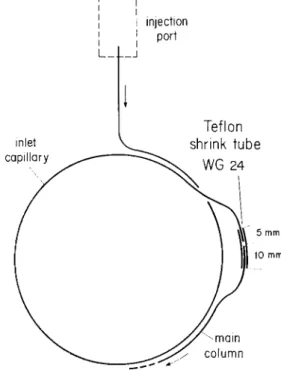
Teflon shrink tube WG 24 inlet capillary injection port L_ mm )) 10 mm -main column
Figure 4. Schematic of connection between main column and short inlet capillary used for splitless injection with sol-vent bypassing.
into the column after 20 sec although a volume of car-rier gas equal to twice the injector volume has been passed up to this time.
The first reasonably, though not perfectly, resolved peak is hexanone. In case of gaseous sampling and under identical flow and temperature conditions 1Fig-ure 2) the hexanone peak begins to broaden when the injection time is about 10 sec. Dwing this time about 1 ml of gas has been fed to the column. The gas vol-ume (at column outlet ) of the introduced liquid sample of 1 111 hexane is 0.2 ml. Assuming a fivefold dilution with carrier gas, this would account for 10 sec injection time. The assumption seems reasonable since, for our small column flow and large sample size, we used a relatively wide injector tube. We conclude from this agreement that the concentration phenomenon is basically the same for gaseous as well as for liquid samples. Apparently it is not strongly Affected by the large amount of solvent.
There is no doubt, on the other hand, that con-tinuous heavy overloading will deteriorate the column. Since the sample components of interest after injection on a relatively cold column are concentrated in a first short length of the capillary, it seemed that it might be possible to vent the bulk of solvent by a bypass at the end of a relatively short inlet piece. As we recently reported (4) repeated cutting and reconnect-ing of capillaries can be done without any loss of per-formance. We therefore cut the column at 1.60 m, measured from the inlet end, and reconnected it in the following manner: A 15 mm piece of Teflon shrink tubing (type WG 24) was fastened by warming on the end of the main column leaving mm of unshrunk tubing beyond the end of the capillary. After putting in this open end a short piece of steel wire with the same diameter as the capillary. we warmed the re-maining 5 mm of Teflon to produce a solid connection of glass and steel. It is easy to withdraw the wire pro-vided its surface is smooth and the part of Teflon covering the wire is not too long. We then introduced the end of the inlet capillary Mto the shrunken Teflon and obtained a perfectly gas-tight connection that can be opened and reconnected many times by simply pull-ing out and reintroducpull-ing the end of the inlet capillary. We have prepared numerous connections of this kind which were used for about 30 operations and at oven temperature of 200°C without leaking. After 30 opera-tions we renew the connection to avoid increasing dis-tortion. The manipulation is facilitated by an appro-priate shape of the parts connected see Figure
The procedure for solvent bypassing is as follows: the disconnected inlet part is fitted int() the injection port. Its open end is joined to a flow restriction valve and a soap bubble meter by means of a thin plastic tube. In case of large solvent sizes we insert a glass tube filled with glass wool between capillary and flow restrictor to protect the restrictor from condensed sol-vent. By applying a low carrier gas pressure — 0.1 at) a constant flow, similar to normal column flow, is achieved with the split valve closed. Injections of up to 1 pl are made rapidly. Larger amounts are intro-duced over a few sec to avoid back-diffusion of the vapors. After an exactly measured time of, e.g.. 30 sec the carrier gas supply to the injection chamber is stopped. After another measured time. during which
the flow decreases to zero, the plastic tube is with-drawn, the inlet part is connected to the main column and normal flow conditions are resumed. The column is heated only after the air, which entered through the open end has been swept out of the cold column.
For a given inlet capillary (i.e. for a given length and diameter and film thickness) the important pa-rameters in this procedure are:
a) the temperature of the inlet capillary, ) the total gas flow through the inlet capillary, c) the total sample size,
d ) the relative volatility of the solvent as well as of the most volatile sample to be resolved.
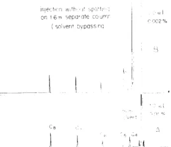
The optimum parameters must be found experiment-ally. The critical point normally is the removal of the solvent from a sample containing very volatile com-ponents, as is the case with the example reported here. In this case either some loss of volatiles or a moder-ate removal of solvent must be accepted. In our case ( Figure 5) the first two or three alkanones are too volatile for prolonged injection (for liquid samples this means splitless) at room temperature. The injec-tion parameters for the chromatograms in Figure 5 are, therefore, chosen to favour effective solvent re-moval, accepting approximately 80% loss of butanone and 60% loss of pentanone; the reduction of hexanone was less than 10%. As for the chromatographic condi-tions, Figure 5A corresponds exactly to Figures 3B and 3C except for solvent bypassing. In contrast, the run 5B accomplished with 5 pl of 0.002% solution can in no way be duplicated without solvent bypassing.
4. Grob, K., and Grob, G., J. Chromatog. Sci., 7, 515 (1969).
ulect,1 't,
or, t 6m separate column soleer t bvpassr(1
Ce
handled the middle and the first part of the inlet in a corresponding fashion (Figures 6C and 6B respec-tively 1. The result was as follows: butanone had com-pletely passed the first 40 cm and was found dis-tributed over the remainder of the tube. More than half of it had been lost together with the solvent. Pen-tanone was detected over the entire tube. The same was observed for hexanone with marked accumulation in the first 40 cm. Heptanone and octanone were ex-clusively present in the first quarter.
In summary, the result is not surprising since all well-resolved substances were concentrated on a rela-tively short piece of capillary. Normally it is sufficient, therefore, to use 50-100 cm inlet capillaries. For analy-sis of volatile substances, lowering the column temper-ature for injection is more effective than lengthening the inlet capillary.
J
Figure 5. Liquid sample, alkanones C4-C,. Splitless injection with solvent bypassing. Size and dilution of sample varied.
remninina
-,econd
4n
c8
Figure 6. Sample and chromatograph,c conditions as for Figure 5A. A: Full solvent bypassing procedure. B-D: Single parts of loaded inlet capillary connected to column. For de-tails of procedure see text.
Note that heptanone and octanone are perfectly re-solved even under these drastic conditions, whereas hexanone suffered an increase of 25(,?,.
We were interested in identifying the parts of the inlet capillary in which the single substances were concentrated. After running a chromatogram Figure 6A) from the whole 1.6 m inkt capillary, we prepared, under identical conditions, a second injection after which we cut the injection capillary into three parts of 40, 40, and 80 cm. To prevent diffusion of the most volatile substances we first connected the last part 80 cm ) to the column and obta Med Figure 61). We
Practical recommendations for solvent bypassing
To obtain the desired performance of the inlet capillary, carefully adjusted conditions are needed. It is inconvenient to reproduce these conditions (and primarily the exact and uniform temperature of the inlet piece ) after every run. We prefer to carry out the injections on an independent apparatus where its conditions are continuously held at the optimum. This second apparatus need not be a gas chromatograph. Since most injections are performed at room tempera-ture), only a heatable injection chamber with an effi-cient flow regulating device is needed. This arrange-ment also offers the opportunity of conveniently im-mersing the inlet capillary in a cooling bath for sub-ambient injection temperature.
It is recommended that more than one inlet part for one column be prepared. During a run the next injection can be performed on a second inlet capillary.
In case of large sample sizes the coating of the inlet capillary may be damaged after a certain num-ber of injections. This can easily be observed in glass capillaries i formation of minute droplets). Rinsing and recoating is done very rapidly since drying but no conditioning of the liquid phase is necessary. We renew the coating after about 20 injections of 5 ,ed liquid samples with a polar solvent.
Except for very volatile substances there is little diffusion in the inlet capillary over a long time. We leave loaded inlet parts with stoppered ends at room temperature overnight without observing reduced reso-lution for substances with boiling points over 200°C. We especially use this opportunity to carry loaded inlet parts over long distances to apparatus not equip-ped with an appropriate injection system for capillary columns i in our case a combination of Ge and MS). Another use of the same effect is taking head space samples at any location by simply drawing headspace gas through an inlet piece and carrying the latter to the laboratory for analysis.
Since efficient trace analysis is achieved with sol-vent bypassing, care is recommended to avoid unin-tentional analysis of silicone septum emollients. Even at injector temperatures of about 200°C, most septa release sufficient bleed material to be concentrated on the capillary and to produce perfect and typical elu-tion patterns.
o 0.01% solution injected on 16m capillary without splitting at 25° comparison of whole
inlet capillary with
Conclusions
From our experimenta I results we deduce a con-centration effect depending on the difference between column temperature and boiling point of sample. As far as we know, this effect has not yet been studied for its merits.
Besides boiling point, another essential parameter is functionality of the sample. When referring to boil-ing point only we presuppose that the sample is run on a column of very similar polarity.
In Part I we have expressed the ruk that splitless injection is practicable if during injection the column temperature is at least 100°C below the boiling point of the most volatile sample component. This rule is confirmed by the observation that hexanone b.p. 126°C) is the most volatile alkanone reasonably re-solved after splitless injection of a large amount of dilute solution on a column at room temperature see Figure 3C, 5A, 5B). The rule holds for substances of any class provided the above-mentioned requirement is met.
Wishing to present average practical examples, we used a liquid phase and samples of medium polarity. Under nonpolar conditions. e.g. with alkanes on a squalane column, the concentration effect is even more pronounced.
Emulphor 0, the liquid phase used, is very viscous at 25°C. This is the reason for the decreasing peak width with increasing C-number measured after rapid injection t Figure 2). The concentration effect itself
has no essential relation to viscosity ti.e. beyond the genera] chromatographic effects of viscosity ). Hitherto we have coated the inlet capillaries with the same liquid phase and the same film thickness as the main column. We are unable to discuss the potential effects caused by changing these variables.
It is our experience that solvent bypassing seems to become more difficult with capillaries of smaller diameter. The influence of column diameter has not yet been studied extensively.
The advantages of our splitless injection procedure have been enumerated in Part I. We consider as the most important advantage the combination of the con-centration effect with the solvent bypassing technique which broadens the application of capillary columns in trace analysis. The procedure does not offer a similar concentration power as that described by Novak, Vasak and Janak (5) but has the advantage of simplicity as well as of direct interpretation of the results.
Acknowledgment
We gratefully acknowledge the generous support of our work by F. J. Burrus & Cie., Boncourt. n
Manuscript received June 26, 1969.
5. Novak, J., Vasak, V. and Janak, J., Anal. Chem. 37, 660 (1965).
Liquid Ethylene-Propylene Copolymers as
Stationary Phase in Gas Chromatography
by 0. Bieber, G. Degler, and H. Schnecko, Dunlop Forschungslaboratorium, Hanau, Germany
Abstract
The use of ethylene-propylene copolymers of lower mo-lecular weight ([97],--.3) for the separation of hydrocarbon mixtures or pyrolysis products from polymers is reported. They can be used as stationary phase up to column tem-peratures of 350°C.
Introduction
Oligomeric and polymeric material has found wide application in gas chromatography (1 ). Synthetic polymers (e.g. Teflon, polyethylene, cross-linked poly-styrene) are used as solid support, and liquids ( e.g. polyethylene glycols, silicones } have been employed as coatings.
Here, the application of a lower molecular weight random ethylene-propylene (EI) copolymer as liquid phase is reported. It can advantageously be used for the separation of aliphatic and aromatic hydrocarbons and of cracked polymer products up to column tem-peratures of 350°C.
Experimental
The EP copolymers were prepared with a VO Cl, /Al-sesquichloride catalyst under atm H,. E-content was 52 mole-%, [n] 0.334, corresponding to mol-wts of ca 15,000. The columns were prepared by mix-ing the bulk copolymer liquid with Chromosorb (5 and 10% coating respectively). Gas chromatography was done on a Perkin-Elmer F6 (isotherm, hot-wire detec-tor, 250°C) and on a Hewlett Packard F & M 5750 instrument (temperature programmed, 2°C/min, FID, 0.2-1.0 pl injected); flash pyrolysis of polymers (ca 5 mg) was conducted at 680°C for 18 sec.
Results
Figure 1 shows the separation power of the EP-liquid phase packing for a normal test mixture of
aro-1. Leibnitz, E., and Struppe, H. G., "Handbuch der Gas-Chromatographie," Verlag Chemie, Weinheim Berg-strasse, West Germany, 1967.