Direct Fabrication of Planar Grating by Ultrafast Laser Beam
K. Venkatakrishnan, C. W. Hee, N. R. Sivakumar, B. K. A. Ngoi
Abstract-Femtosecond laser pulse has been
used for the machining of the gratings primarily due to its superior advantages over conventional continuous wave (CW) and long pulse lasers for micromachining. In this paper, we develop a novel technique for the fabrication of planar gratings by colliding two beams to generate interference fringes. This technique is simple, fast and low cost. We have successfully fabricated planar gratings on a copper substrate.
INTRODUCTION
The recent development of femtosecond pulsed lasers has stimulated interest in the field of optical devices, for instance, fiber Bragg gratings1, 2, waveguides3, 4, micro-optics etc.
The fabrication of planar Bragg grating by colliding a pair of femtosecond laser pulses in a transparent material has been reported.5 The reported experimental setup consists of a regeneratively amplified pulse of ML-Ti sapphire laser, split into two beams by using a half mirror. The two beams, which form an angle (θ ) of 10 to 30° to each other are focussed beneath a top surface of a single crystal diamond. The timing of the pulse is adjusted by using optical delay line. The irradiation induces morphological changes on surface or near-surface regions of the specimen. A periodic line pattern with a constant spacing of ~2.5µm has been reported.
K.Venkatakrishnan is with the Precision Engineering and Nanotechnology Centre, School of Mechanical and Production Engineering, Nanyang Technological University, Nanyang Avenue, Singapore 639798
C.W. Hee is with the Precision Engineering and Nanotechnology Centre, School of Mechanical and Production Engineering, Nanyang Technological University, Nanyang Avenue, Singapore 639798 N. R. Sivakumar is with the School of Mechanical and Production Engineering, Nanyang Technological University, Nanyang Avenue, Singapore 639798
B.K.A Ngoi, is with the Innovation in Manufacturing Systems and Technology(IMST), Singapore-MIT Alliance (SMA), N2-B2c-15, Nanyang Technological University, Nanyang Avenue, Singapore 639798
The experiment reported involves complex setup and in addition to it optical delay is introduced to compensate for the optical path length of the interfering beams. Sub-micrometer displacements in the position of mirrors, beam splitter, or other optical mounts in the interferometer during UV irradiation will cause the fringe pattern to drift, washing out the grating from fiber. Furthermore, due to the laser light travels long optical path lengths, air currents, which affect the refractive index locally, can become problematic and degrade the formation of a stable fringe pattern. However, in this paper, a novel interference technique is proposed for the fabrication of planar gratings. The main advantage of this technique is to reduce the number of optical components required to generate interference. We have succeeded in the formation of planar grating by this method on a copper substrate.
EXPERIMENTS AND RESULTS In our experiment, a chirped pulsed amplification (CPA) Ti:sapphire system is used. This system comprises of a pulse stretcher, a regenerative amplifier that pumped by a Nd:YLF laser and a compressor. This laser system generates pulses operating at a wavelength of 800nm with duration of 150fs at a repetition rate of 1kHz. The amplified pulses coming out from the compressor module is frequency-doubled to 400nm by using a second harmonic generator, i.e. BBO crystal. Consequently, the laser was split into two beams of equal intensity and then recombined them onto a 2”x 2” copper substrate by a focusing lens to produce interference fringes. Moreover, a quarter wave plate can be used to achieve equal intensity that subsequently generating the high contrast of interference fringe pattern. The basic requirement for two beams to generate interference fringes is the optical path difference (OPD) should not exceed the coherence length, Lc of laser pulses, i.e.
60µm. In other words, the high interference fringes are generated when the femtosecondlaser pulses are temporally overlapping. The fringe spacing, d is given by d = λ/[2sinθ / 2)], where λ denotes the wavelength while θ denotes the angle between two intersecting beams. The
spacing, d can be varied by changing λ and θ. Meanwhile the number of fringes depends on the beam size, φ and the spacing, d. The ablated gratings are observed using scanning electron microscope. Figure 1 shows that the scanning electron micrograph (SEM) of the surface relief gratings with number of gratings is 6.
Figure 1 SEM showing the planar Bragg gratings fabricated on copper substrate. (spacing, d = 6.4_m; cross beam angle, θ =
3.58°; focal length, FL =200mm)
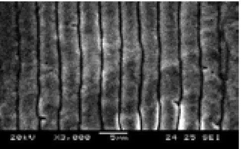
Figure 2 shows that the result of changing of cross beam angle, θ. By calculation, the spacing, d and number of gratings will increase concurrently. From Figure 2, the spacing is reduced to 3.2m and the number of fringes is increased to 12. From both figures, a constant spacing of linear grating can be clearly seen which indicate that the viability of this technique to fabricate planar grating.
Figure 2 SEM showing the planar Bragg gratings fabricated on copper substrate. (spacing, d = 3.2_m; cross beam angle, θ =
7.51°; focal length, FL =200mm)
CONCLUSION In summary, by colliding a pair of two
femtosecond laser pulses, fine-pitched micrograting can be fabricated on copper substrate. This method offers a novel technique for fabricating microgratings on the surface. Future work would involve machining on different materials, especially silica glasses,
which are the common materials for optical devices. Besides, the grating spacing will be further reduced and the grating frequency will be increased. We anticipate the present technique will open novel frontiers in micromachining utilizing femtosecond pulses.
REFERENCES
Fertein, E., Przygodzki, C., Delbarre, H., Hidayat, A., Douay, M., & Niay, P. (2001). Refractive-index changes of standard telecommunication fiber through exposure to femtosecond laser pulses at 810nm. Applied Optics, 40 (21), 3505-3508.
Kondo, Y., Nouchi, K., & Mitsuyu, T. (1999). Fabrication of long-period fiber gratings by focused irradiation of infrared femtosecond laser pulses. Optics Letters, 24 (10), 646-648.
Hirao, K., & Miura, K. (1998). Writing waveguides and gratings in silica and related materials by a femtosecond laser. Journal of Non-Crystalline Solids, 239, 91-95.
Davis, K.M., Miura, K., Sugimoto, N., & Hirao, K. (1996). Writing waveguides in glass with femtosecond laser. Optics Letters, 21 (21), 1729-1731.
Kawamura, K., Sarukura, N., Hirano, M. and Hosono, H. (2000). Holographic encoding of permanent gratings embedded in diamond by two beam interference of a single femtosecond near infrared laser pulse. Jpn. J. Appl. Phys. 39, L767-L769.