Publisher’s version / Version de l'éditeur:
Fire Technology, 35, November 4, pp. 336-361, 1999-11-01
READ THESE TERMS AND CONDITIONS CAREFULLY BEFORE USING THIS WEBSITE. https://nrc-publications.canada.ca/eng/copyright
Vous avez des questions? Nous pouvons vous aider. Pour communiquer directement avec un auteur, consultez la
première page de la revue dans laquelle son article a été publié afin de trouver ses coordonnées. Si vous n’arrivez pas à les repérer, communiquez avec nous à [email protected].
Questions? Contact the NRC Publications Archive team at
[email protected]. If you wish to email the authors directly, please see the first page of the publication for their contact information.
NRC Publications Archive
Archives des publications du CNRC
This publication could be one of several versions: author’s original, accepted manuscript or the publisher’s version. / La version de cette publication peut être l’une des suivantes : la version prépublication de l’auteur, la version acceptée du manuscrit ou la version de l’éditeur.
For the publisher’s version, please access the DOI link below./ Pour consulter la version de l’éditeur, utilisez le lien DOI ci-dessous.
https://doi.org/10.1023/A:1015453014065
Access and use of this website and the material on it are subject to the Terms and Conditions set forth at
Examination of the extinguishment performance of a water mist system using continuous and cycling discharges
Liu, Z. G.; Kim, A. K.; Su, J. Z.
https://publications-cnrc.canada.ca/fra/droits
L’accès à ce site Web et l’utilisation de son contenu sont assujettis aux conditions présentées dans le site LISEZ CES CONDITIONS ATTENTIVEMENT AVANT D’UTILISER CE SITE WEB.
NRC Publications Record / Notice d'Archives des publications de CNRC:
https://nrc-publications.canada.ca/eng/view/object/?id=4887d6f9-6b67-4de3-aa57-3d0c66d836c3 https://publications-cnrc.canada.ca/fra/voir/objet/?id=4887d6f9-6b67-4de3-aa57-3d0c66d836c3
Examination of the extinguishment performance of a water mist system using continuous and cycling discharges
Liu, Z.; Kim, A.K.; Su, J.Z.
NRCC-41870
A version of this document is published in / Une version de ce document se trouve dans : Fire Technology, v. 35, no. 4, Nov. 1999, pp. 336-361
Examination of the Extinguishment Performance of a Water
Mist System Using Continuous and Cycling Discharges
Zhigang Liu, Andrew K. Kim and Joseph Z. Su Fire Risk Management Program
Institute for Research in Construction
National Research Council of Canada, Ottawa, Canada, K1A 0R6
ABSTRACT
A series of full-scale fire tests of a twin-fluid water mist system was conducted in an empty enclosure and in a simulated machinery space. During the tests, two water mist discharge modes (continuous and cycling) were used. The extinguishment performance of the water mist system using these two discharge modes was investigated under various fire scenarios, including different fire sizes, types and locations, and different ventilation conditions. The test results showed that the use of the cycling discharge substantially improved the effectiveness of the water mist system for fire suppression, in comparison to the continuous discharge. The corresponding extinguishing time and water
requirement for fire suppression were significantly reduced, and some fires that could not be extinguished by the use of the continuous discharge were extinguished by the use of the cycling discharge. The improvement in fire suppression was attributed to high depletion and dilution rate of oxygen and the recurrent dynamic mixing generated by the cycling water mist discharge in the compartment.
Key Words: fire extinguishment, water mist, continuous and cycling discharges INTRODUCTION
With the recent phase-out of halons and the search for alternative agents, water mist fire suppression systems have received renewed attention [1, 2]. These fire
suppression systems have the potential either to replace current fire protection techniques no longer deemed environmentally acceptable, or to provide new answers to problems where traditional technologies have not been as effective as desired. Their efficacy for fire protection has been demonstrated in a wide range of applications and by numerous experimental programs, including the extinguishment of Class B spray and pool fires in shipboard machinery spaces and engine room spaces, the extinguishment of Class A fires in the shipboard accommodation spaces and heritage property (wood stave churches and libraries), the extinguishment of Class C fires in computer room and electronic
equipment, as well as fire extinguishment in aircraft onboard cabin and cargo
compartment [3-10]. The evaluation of the capabilities and limitation of water mist fire suppression systems also indicates that water mist in fire suppression does not behave like a gaseous agent, and is substantially affected by the fire size, the degree of obstruction and the ventilation conditions in the compartment [11, 12]. Some new technologies, such as the combination of local and total flooding application for the protection of the machinery spaces [13], the combination of intelligent detection with
zoned water mist systems for use on electronic equipment [14], and the combination of additives with water mist [15], have been developed to improve the effectiveness of water mist fire suppression systems.
Recently, a series of full-scale fire tests was carried out by the National Research Council of Canada (NRC) to study the use of the cycling discharge mode for the
improvement of the extinguishment performance of the water mist fire suppression system. The cycling water mist discharge means that during fire suppression, the discharge of water mist is turned “on” for a short period of time, followed by a short period during which water discharge is turned “off”, and this cycle is continuously repeated. The cycling water mist discharge was initially used for the fire extinguishment in gas turbine enclosures [13, 16]. It was reported that the cycling water mist discharge could reduce the damage to critical turbine components due to the stress cracking or excessive deformation caused by rapid spray cooling. However, the effect of the cycling discharge mode on the performance of water mist fire suppression systems was not studied.
This paper reports the test results obtained from NRC’s full-scale tests in which the extinguishment performance of the water mist system using the continuous and cycling discharge modes was studied and compared under various fire scenarios with different fire sizes, types and locations, and with different ventilation conditions. The effect of two discharge modes on the effectiveness of the water mist fire suppression system is analysed by examining the changes in room temperatures, gas concentrations and dynamic mixing in the compartment. The factors that contribute to the improvement of the efficacy of the water mist fire suppression system using the cycling discharge are then discussed.
TEST FACILITY AND FIRE SCENARIOS
The test facility consisted of a specially-constructed compartment, a water distribution network and appropriate instruments to monitor and record the test results.
Test Room
The test room was an irregular-shaped, rectangular room with dimensions of 9.7 m x 4.9 m x 2.9 m high, and with a corner (2.9 m x 2.2 m) removed. A plan view and elevation view of the room are shown in Figures 1 and 2. The test room had a 2.0 m x 0.9 m high door and three 0.56 m2 viewing windows. The room also had a 0.5 m x 0.5 m pressure relief vent attached to a fan in the south wall near the floor. The vent was only open when the tests were conducted under forced ventilation conditions.
Fire Scenarios
The full-scale tests were conducted in an empty enclosure and in a simulated machinery space. During the tests, different fire sizes, types and locations, and different ventilation conditions were used to investigate the extinguishment performance of the
water mist system using two discharge modes. Each type of fire size was determined by measuring its heat release rate in the open by oxygen consumption calorimetry. These fire sizes were the free burn levels and may be changed with surrounding conditions (e.g., oxygen concentrations) during fire suppression.
Tests in an Empty Enclosure
For the test series in the empty enclosure, the heptane fuel testing fires included tell-tale (TT) fires, square-pan (SP) fires, a round-pan (RP) fire and a spray fire. To investigate the performance of the water mist system against unshielded small fires in the different locations of the compartment, eight TT fires, each in 75 mm diameter can, and three square-pan fires with dimensions of 0.3 m x 0.3 m were placed strategically throughout the room at different elevations or located at the corners of the compartment (see Figures 1 and 2). The total heat output of these eight TT fires was approximately 50 kW. The heat output of each square-pan fire was approximately 50 kW.
To investigate the performance of the water mist system against the shielded fires, one metal box with dimensions of 0.80 m x 0.84 m x 0.94 m high was placed mid-room, between two water mist nozzles. The top of the box was made by a layer of sheet metal with holes that constituted a 6% opening ratio. The sides of the box were made by the metal mesh with a 33% opening ratio. For large shielded pool fire tests, a round pan of 0.7 m diameter was placed in the metal box and produced a heat output of approximately 500 kW. For the shielded spray fire tests, one spray nozzle was placed in the box. The operating pressure of the spray fuel was 5.8 bar and the spray fire produced a heat output of approximately 520 kW.
Tests in a Simulated Machinery Space
For the test series in the simulated machinery space, a diesel engine mock-up, which was mainly based on the fire test protocol recommended by Factory Mutual Research Corporation, was set up in the compartment (see Figures 3 and 4). To simulate the lower portion of the turbine casing, a solid metal table (0.6 m high) was placed in the center of the room while the perimeter of the table was fitted with 0.85 mm thick
galvanized sheet metal. The sheet metal was installed at a 45o angle with respect to the table. The space below the plate was partially shielded by using two 0.3 m high x 0.3 m long sheet metal baffles.
For large shielded pool fire tests, a heptane pool fire in a round pan of 0.7 m diameter was placed under the table and produced a heat output of approximately 500 kW. For small shielded heptane pool fire tests, three 0.3 m square-pans were placed under the table. These three square-pan fires produced a total heat output of 150 kW. For the shielded spray fire tests, one spray nozzle was placed under the table with an upward angle of 20o to strike the center of the table. The operating pressure of the spray fuel was 5.8 bar and the spray fire produced a heat output of approximately 520 kW.
During the tests in the simulated machinery space, the effect of air convection into the room on the water mist performance was investigated. The ventilation
conditions used in the tests included the door closed, the door open (natural ventilation) and the combination of the door open with an exhaust fan running (forced ventilation). The flow rate of the exhaust fan was 0.737 m3/s.
Water Mist System
A twin-fluid water mist system was used in the tests. The twin-fluid nozzle had seven orifices that produced a flow capacity of 5 L/min and a spray cone angle of 90o. The operating pressures of the nozzle for water and air were 5.78 bar and 5.57 bar, respectively. The droplet size distribution of the water mist generated by the nozzle was a Class II spray (200 µm < Dv0.9 < 400 µm).
The pipe network layout for water and air in the compartment, including nozzle number and location, was based on the guidelines provided by the manufacturer, and is shown in Figures 1 and 2. Fourteen nozzles were installed on the ceiling. The spacing of the nozzles was 1.63 m x 1.88 m. The distance from the side nozzles to the south and north walls was 0.94 m, and to the east and west walls was 0.82 m. One nozzle was located 0.7 m from the door of the room. The total water discharge rate of the system was 70 L/m.
During the test series, two water discharge modes were used: continuous and cycling. For cycling discharges, the frequency of water mist discharge was: 50 s on and 30 s off in the test series conducted in the empty enclosure and 30 s on and 20 s off in the test series conducted in the simulated machinery space. The duration of water “on” and “off” in the cycling discharge was determined mainly based on the fire scenarios set up in the empty and the simulated machinery spaces.
Instrumentation
Three thermocouple trees, as shown in Figures 3 and 4, were set up in the room to measure room temperatures. Each tree contained six thermocouples at 0.56 m vertical intervals. The thermocouples were 30-gauge, chromel-alumel Type-K, with stainless-steel sheaths, each 1.6 mm in diameter. To monitor the extinguishment of fires, thermocouples were placed 50 mm directly above the centre of the fuel surface at each fire location. During the tests within the empty enclosure, four thermocouples were placed above the centre of the fuel surface of the round-pan fire and their locations were 0.48 m, 0.93 m, 1.83 m and 2.73 m from the floor, respectively.
Two copper gas sampling ports, 12 mm in diameter, were located in the west wall as shown in Figures 3 and 4. One sampling port, 1.5 m above the floor and projecting 0.3 m into the room, was used to measure the concentrations of CO and CO2. Another
sampling port, 2.8 m above the floor and projecting 0.3 m into the room, was used to measure the concentrations of O2, CO and CO2 in the compartment. The gases were
then measured by two Siemens Ultramat 22P Series for CO and CO2 concentrations and
one Siemens Oxymat 5E O2 analyzer for O2 concentration.
Nine pressure taps were installed on the west wall to monitor the pressure changes in the room (see Figures 3 and 4). Three pressure taps were located at each of three elevations (top, middle and bottom). The pressure taps at each location were manifolded to give an average pressure reading.
Two video cameras were set up at the south and north windows to obtain visual records of the water mist discharge and the behaviour of the fires under suppression.
Test Procedure
For all full-scale tests, test fires were allowed at least a 30 s pre-burn period before suppression commenced. During the pre-burn period, the door was kept open to allow fresh air to enter the room. This minimized the oxygen reduction in the
compartment. At the beginning of the water mist discharge, the door was either kept open or closed, depending on the ventilation conditions for the test. For the test with forced ventilation in the room, the exhaust fan that was attached to the pressure relief vent started at the same time as the activation of the water mist system.
Fire suppression processes were directly observed through three windows of the compartment and monitored by thermocouples placed at each fire location. Test data were recorded at 1 second of intervals. Fire extinguishment was determined by both visual observation and fire temperatures measured at each of the fire location. Before it was assumed that the water mist system was unable to extinguish the fire, the fire was allowed to burn 7 to 16 minutes, depending on fire conditions observed and the changes in oxygen concentration in the compartment.
RESULTS
The test results using two water mist discharge modes in the empty enclosure and in the simulated machinery space are listed in Tables 1 to 3, respectively. The
extinguishment time is defined as the time interval between the activation of the water mist system and the instant of fire extinguishment. The average water quantity (Wd) per
area used in the tables is defined as the ratio of the total amount of water (Wt) discharged
in the testing period over the total compartment area (Ac):
W W A d t c = (L/m2) (1)
Test Results in the Empty Enclosure
As shown in Table 1, eight tell-tale fires and three square-pan fires were used in Test 1-1. Four tell-tale fires (#52, #54, #55 and #56) were placed at the corners of the
compartment and three tell-tale fires (#49, #54 and #57) were located near the ceiling (77 mm away from the ceiling). Three square-pan fires were placed, separately, at three corners of the compartment. Compared to the size of the compartment, heat output (200 kW) produced by these fires was small, and the fires were hardly hit by water mist due to their positions in the compartment, presenting a greater challenge for fire extinguishment by water mist.
Table 1 shows that all tell-tale fires in the tests were extinguished by the continuous water mist discharge. The tell-tale fires located near the ceiling or at the corners were the most difficult tell-tale fires to extinguish. One square-pan fire (#51) located at the mid-height of the compartment was extinguished, while two other square-pan fires (#48 and #53) located on the ground at the corners were not extinguished due to the corner effects. The test period using the continuous water mist discharge was 417 s and the average water quantity per unit area discharged was 11.87 L/m2.
For the same fire scenario (Test 1-2), the use of the cycling water mist discharge extinguished all tell-tale fires and two square-pan fires, and only one corner square-pan fire (#53) was not extinguished. Compared to the continuous discharge, extinguishing times for some tell-tale fires were increased but for others were reduced. The use of the cycling discharge reduces water requirement from 11.87 L/m2/ to 8.5 L/m2, although the testing period was longer than the test using the continuous discharge.
To study the effectiveness of the water mist system in suppressing large fires, one large round-pan fire (500 kW) was placed in the compartment and partially shielded by a metal box without the side metal mesh, while eight tell-tale fires and three square-pan fires were kept at the same locations as in the small fire tests (Tests 1-1 and 1-2). The total heat release rate of the fires in Tests 1-3 and 1-4 was 700 kW. The use of the continuous water mist discharge (Test 1-3) could not extinguish one corner square-pan fire (#48), and the partially shielded pool fire was extinguished at 210 s. With the cycling water mist discharge (Test 1-4), all the fires in the compartment were
extinguished and the corner square-pan fire (#48) was the last fire to be extinguished at 175 s. The extinguishment time for the partially shielded round-pan fire was reduced from 210 s to 110 s. The average water quantity required for fire extinguishment was 3.3 L/m2 and much less than that using continuous discharge (750 s discharge period and 21.34 L/m2 water quantity).
During Tests 1-5 and 1-6, the corner square-pan fire (#48) was moved out from the corner and placed 0.3 m from each wall, and the round-pan fire was fully shielded by a metal box with the side metal mesh. Test results showed that the use of both
continuous and cycling water mist discharges extinguished all the fires in the
compartment, but the times for the extinguishment of the shielded round-pan fire using both continuous and cycling discharge were increased. Such increase was significant by the use of the continuous discharge (210 s to 300 s) and less significant by the use of the cycling discharge (110 s to 115 s). Compared to the continuous discharge, the use of the cycling water mist discharge reduced total extinguishment time from 300 s to 130 s and
water requirement from 8.5 L/m2 to 2.9 L/m2, showing a significant improvement in fire suppression.
Test Results in the Simulated Machinery Space
During Test 2-1 conducted in the simulated machinery space, three small square-pan fires were placed side-by-side under the table and produced a small heat output (150 kW) in the compartment. It was observed that these three shielded side-by-side square-pan fires burned independently and were difficult to extinguish simultaneously. During the 960 s continuous discharge, the average room temperature was kept at around 50oC and the oxygen concentration in the compartment was gradually reduced to 15.8%. The use of the continuous discharge, however, failed to extinguish the fires. For the same fire scenario in Test 2-2, the use of the cycling discharge extinguished all three side-by-side square-pan fires at 180 s and the quantity of water required was 3.5 L/m2 and much less than that using the continuous discharge (28.1 L/m2).
For the large shielded round-pan fire tests conducted in the simulated machinery space (Tests 2-3 and 2-4), the shielded round-pan fire was extinguished at approximately the same time by both continuous and cycling discharges (114 s for the continuous discharge and 115 s for the cycling discharge). However, the use of the cycling discharge reduced the water requirement from 3.1 L/m2 to 2.1 L/m2.
For the shielded heptane spray fire (Tests 2-5 and 2-6), the use of the continuous water mist discharge extinguished the fire at 113 s, while the use of the cycling discharge extinguished the same fire at 130 s. The extinguishing time was longer than that using the continuous discharge. However, the use of the cycling discharge reduced the water requirement from 3.1 L/m2 to 2.7 L/m2.
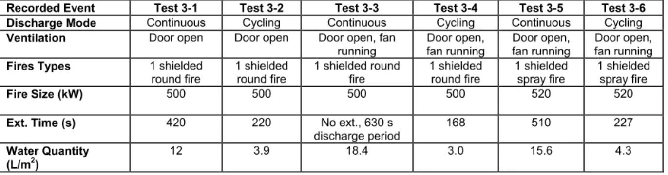
When the door of the compartment was kept open in Tests 3-1 and 3-2, fresh air flew into the room, and the effectiveness of water mist in fire suppression was affected by the ventilation in the room. It took 420 s for the continuous discharge to extinguish the shielded pool fire, which was significantly longer than that with the door closed in Test 2-3 (114 s). The extinguishing time for the ventilated fire also increased by the use of the cycling discharge (115 s to 220 s). However, compared to the continuous
discharge, the use of the cycling water mist discharge improved the water mist
effectiveness against ventilated fires. It reduced the extinguishment time for the same fire from 420 s to 220 s and the amount of water required for fire extinguishment from 12 L/m2 to 3.9 L/m2.
When the door of the compartment was kept open and the exhaust fan was kept running in Tests 3-3 and 3-4, the forced ventilation occurred in the compartment. Fresh air was vented into the room, while a part of steam and hot gases was pumped out of the room through the exhaust fan. The use of continuous water mist discharge could not extinguish the shielded round-pan fire under such ventilation conditions after a 630 s discharge period. However, the use of the cycling water mist discharge extinguished the same fire at 168 s. The quantity of water used in the test was 3 L/m2. Compared with
using the cycling discharge in Test 3-2 with the door open, the extinguishing time for the same fire in Test 3-4 with both door open and fan running was even reduced. This might be attributed that with the assistance of more fresh air in Test 3-4, the fire was bigger in both the water-on and off periods and consumed more oxygen and produced more steam than that in Test 3-2, resulting in an early fire extinguishment. It was observed that the minimum oxygen concentration measured in Test 3-4 was 16.4% and 0.6% lower than that measured in Test 3-2 using the same cycling discharge, and the maximum CO2
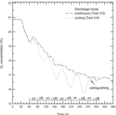
concentration measured in Test 3-4 was 3.3% and 0.5% more than that in Test 3-2. For the shielded heptane spray fire under forced ventilation conditions (Tests 3-5 and 3-6), both the continuous and cycling water mist discharges extinguished the
shielded spray fire, but the extinguishing times were much longer than those without ventilation in the room (Tests 2-5 and 2-6). Compared to the continuous discharge, however, the cycling discharge reduced the extinguishment time from 510 s to 227 s and the water requirement from 15.6 L/m2 to 4.3 L/m2, showing a significant improvement in suppressing forced ventilation fires.
DISCUSSION
These test results showed that when fire challenges were such that water mist could easily extinguish the fires (Tests 2-3 to 2-6), the reduction in the extinguishing time using the cycling discharge mode was not significant. However, the use of the cycling water mist discharge reduced the amount of water required for fire suppression. For more challenging fire conditions, such as small fires (Tests 1-1 and 1-2) and shielded fires (Tests 1-3 to 1-6) or fires under ventilated conditions (Tests 3-1 to 3-6), the use of the cycling discharge significantly reduced the extinguishment times and water
requirements, showing a great improvement in the fire suppression. The use of the cycling water mist discharge also extinguished those small fires (Tests 2-1 and 2-2) and fires under forced ventilation conditions (Tests 3-3 and 3-4) that could not be
extinguished by the continuous discharge. In this section, the extinguishing performance using the continuous and cycling water mist discharge modes will be analyzed and discussed by examining the changes in gas concentrations (O2 and CO2), gas
temperatures and dynamic mixing in the compartment.
Water mist suppresses fires mainly by the means of physical suppression: cooling the fire plume, wetting/cooling the fuel, displacing the oxygen and fuel vapour available for the fire and radiant heat attenuation, when fine water droplets rapidly absorb heat from the fire and the hot surface, and evaporate and expand to steam. During fire suppression, therefore, any measures that would assist to reduce the oxygen
concentration and to increase water vapour or hot gases in the compartment will increase water mist effectiveness in fire suppression.
Figures 5 and 6 show the temperature profiles above the shielded round-pan when the continuous and cycling water mist discharges (Tests 1-5 and 1-6) were used,
separately, for the same fire scenario. In the tests, thermocouple No. 4 was located inside the metal box and close to the fuel surface of the round pan, while other thermocouples
were located outside the box. These thermocouples were used to measure the round-pan fire temperatures and the changes in the fire size during fire suppression. As observed in the test, with the continuous water mist discharge, the shielded round-pan fire was effectively controlled and restricted to the inside of the box. Only the temperature located inside the box was still high and fluctuated (see Figure 5). The shielded fire, however, could not be quickly extinguished. The flame became small and was attached to the fuel surface of the round-pan. It took 300 s for the continuous discharge to extinguish the shielded round-pan fire.
With the cycling water mist discharge, as observed in Test 1-6, the shielded round-pan fire was also effectively controlled and restricted to the inside of the box during the water-on period. The corresponding fire temperatures decreased, as shown in Figure 6. When the water mist discharge stopped, the round-pan fire quickly recovered and became large enough to reach outside the box. The fire temperatures measured by four thermocouples significantly increased, compared to the temperatures during the water-on period. At the beginning of the subsequent water discharge, a momentary increase in the size of the round-pan fire was observed, but soon after the fire was quickly controlled and extinguished. The extinguishment time of the round-pan fire was 115 s and much shorter than that using the continuous discharge for suppressing the same fire.
The changes in the fire size during fire suppression affected the O2 concentration
in the compartment, the room temperatures, the production of water vapour and hot gases, and then affected the fire suppression effectiveness of the water mist. Figure 7 compares the changes in dry oxygen concentration in the compartment, when the continuous and cycling discharges were used, separately, for the same fire scenario. With the continuous discharge (Test 1-5), the oxygen concentrations in the compartment decreased slowly, because the fires in the compartment were controlled and became small as observed in the tests. The depletion of the oxygen by the fires was severely retarded. With the cycling water mist discharge (Tests 1-6), however, the oxygen concentrations in the compartment quickly decreased. As shown in Figure 7, during the water-off period, the oxygen concentrations near the ceiling were reduced significantly, because the
suppressed fires quickly recovered and were allowed to burn freely. When the water mist was applied, the oxygen concentration near the ceiling had an increase due to the re-stratification of gas in the compartment. At the end of fire suppression in Test 1-6, the oxygen concentration in the compartment was approximately 0.6% lower than that using the continuous discharge at the same testing time.
Increase in oxygen depletion using the cycling discharge can be further observed in Figure 8 in which the continuous and cycling discharges were used, separately, to extinguish small shielded fires in the machinery space (Tests 2-1 and 2-2). It can be seen that oxygen concentration in the compartment also fluctuated with the cycling discharge. Recovered fires in the water-off period quickly reduced the oxygen concentration in the compartment. When the shielded fires were extinguished at 240 s by the cycling
discharge (180 s discharge period), oxygen concentration in the compartment was around 0.8% lower than that using the continuous discharge for the same fire scenario. These
results show that with the cycling discharge, more oxygen was consumed by the recovered fires during the water-off period, and the oxygen concentration in the compartment was lower than that using the continuous discharge for the same fire scenario.
During fire suppression, the oxygen concentration in the compartment is further reduced by the volumetric expansion of the water, when water droplets are converted to steam and the volume occupied by the water increases over three orders of magnitude [17]. If the vaporization of the water occurs in the flame, the volumetric expansion can disrupt the entrainment of air (oxygen) into the flame. For the same spray characteristics of the water mist system (droplet size distribution, spray pattern and spray velocity), the quantity of fine water droplets converted into steam is mainly determined by the fire size and the compartment temperatures [17, 18].
Figures 9 and 10 show the changes in the room temperatures using two water mist discharge modes, alternatively, for the same fire scenario. These room temperatures were measured at thermocouple tree #3 with different elevations. It can be seen that during the pre-burn period of the tests, a hot layer was formed near the ceiling and the gas
temperature near the ceiling was heated to around 125oC. When water mist was discharged downward from the ceiling level, the gas temperature near the ceiling was cooled down. Under steady-state conditions with the continuous water mist discharge, the fire was controlled, and the room temperatures tended to be uniform throughout the compartment and were kept around 50oC. With such small fires and low room
temperatures, less water vapour could be generated in the continued water mist discharge. This retarded the efficacy of the water mist in fire suppression.
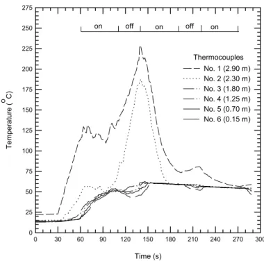
With the cycling water mist discharge, as shown in Figure 10, the gas temperature near the ceiling was kept higher than 100oC and significantly fluctuated during the test period. When the water discharge stopped, the suppressed fires quickly recovered and the thickness of the hot gas layer near the ceiling increased. The gas temperature near the ceiling was further increased and higher than 200oC during the water-off period. As a result, free water fog suspended in the compartment was able to convert into water vapour during the water-off period. Also, when the water mist was discharged again, more water vapour was further produced in the interaction of water mist with large flames, hot gases and hot surface. Therefore, compared to the continuous discharge, the use of the cycling discharge was able to produce more water vapour to dilute oxygen and fuel vapour available for the fires, enhancing the effectiveness of the water mist in fire suppression.
Figure 11 compares the changes in the production of CO2 concentrations in the
compartment using two discharge modes for the same fire scenario. It can be seen that more CO2 concentrations in the compartment were produced by using the cycling
discharge due to the free burning of the fires in the water-off period. This also assisted the fire suppression by water mist.
Another important factor that contributed to enhancing the fire extinguishment was the recurrent dynamic mixing in the compartment created by the cycling discharge. As shown in Figures 7 to 11, with the activation of the water mist system, CO2
concentrations and gas temperatures in the upper part of the compartment were quickly reduced, while the CO2 concentrations and gas temperatures in the low portion of the
room as well as O2 concentrations near the ceiling sharply increased. The gas
concentrations and temperatures tended to be uniform throughout the compartment after the activation of the water mist system. This is because when water mist was discharged from the ceiling level, the water droplets and steam, together with the combustion
products in the hot layer, was pushed downward to mix with the gases near the floor of the compartment and recirculated in the compartment. The level of the gas mixing in the compartment, induced by the water spray, is mainly dependent on the spray
characteristics (droplet size, spray momentum, spray angle, flow rate, etc.) [19, 20, 21]. In addition, the induced airflow rate by the water spray increases with the surrounding temperature, because the downward buoyancy on the gas produced by the spray cooling of induced airflow increases with the surrounding temperature [20, 21]. The dynamic mixing between the upper layer and the lower layer of the compartment is also enhanced with the increase in the mass or thickness of the upper layer [21]. With the use of the cycling discharge, higher compartment temperatures and more water vapour and combustion products were generated as observed in the tests, which created a stronger dynamic mixing in the compartment than that using the continuous discharge. Such strong dynamic mixing occurred at each recurrent cycling discharge, while for the continuous discharge, the dynamic mixing only occurred once at the commencement of the water mist discharge. With the assistance of the dynamic mixing, the steam and vitiated gases were redirected back to the fire, and diluted the air and fuel vapour available for the fires, resulting in more effective fire extinguishment.
The strong dynamic mixing created by the cycling discharge further enhanced the water mist capability against ventilated fires. This can be observed in the changes in room temperatures shown in Figures 12 and 13, when the continuous and cycling discharges were used, separately, for the extinguishment of a spray fire under forced ventilation conditions. These room temperatures were measured at the location of thermocouple tree #2 that was close to the opening door. With the use of the continuous discharge in Test 3-5 (Figure 12), the dynamic mixing was strong at the beginning of the discharge, resulting in quick increase in the gas temperatures at the low part of the compartment. The room temperatures tended to be uniform vertically. However, after a certain test period, the dynamic mixing in the compartment was weakened as a part of the steam and combustion products was vented out the compartment and less steam was produced under low room temperature. As a result, fresh air from outside of the room could penetrate into the interior of the room, and the temperatures at the low portion of the compartment were no longer uniform vertically, increasing the difficulty for fire suppression by water mist.
For the same fire scenario (Test 3-6), Figure 13 shows that gas temperatures in the compartment significantly fluctuated with the cycling discharge. During the water-off period, the gas temperature in the upper part of the compartment was quickly
increased, while the gas temperatures near the floor dropped as the fresh air was vented into the room. When the water mist was applied, the dynamic mixing was so strong that the gas temperature near the floor quickly increased around 40oC and the gas
temperatures in the low portion of the compartment tended to be uniform vertically during the whole water-on period, showing the less impact of fresh airflow on fire suppression.
Figure 14 further shows that dynamic mixing created by the cycling discharge resulted in significant changes in the oxygen concentration near the ceiling at each recurrent cycling discharge. Although under ventilation conditions, the reduction in the oxygen concentration in the compartment using the cycling discharge was not so
substantial as observed under non-ventilation conditions, the use of the cycling discharge was still able to produce a large amount of water vapour to dilute the oxygen and fuel vapour as the fires recovered and heated the compartment even more quickly in the water-off period than that under non-ventilation conditions. In addition, the strong recurrent dynamic mixing hindered outside air flowing into the interior of the compartment and effectively reduced the interference of the ventilation in fire
suppression [22]. As a result, the use of the cycling discharge still performed better than the use of the continuous discharge under ventilated conditions.
During the test series conducted in the empty and simulated machinery spaces, two different cycling frequencies were used in various fire scenarios. However, these cycling frequencies might not be the optimum one for fire scenarios applied. The optimum cycling frequency was mainly dependent on the spray characteristics, fire size and ventilation conditions in the compartment. Figures 15 and 16 compare the changes in oxygen concentration and gas temperatures in the upper part of the compartment, when the same cycling discharge frequency was used, separately, for two fire sizes in Tests 1-2 and 1-6. With large fires in the compartment (Test 1-6), the oxygen concentration was quickly reduced and high gas temperatures were built up near the ceiling during the water-off period. These resulted in quick fire suppression. For the small fires in the compartment (Test 1-2), however, the reduction in the oxygen concentration during the water-off period was much smaller than that with the large fires. Also, the gas
temperature near the ceiling with small fires increased more slowly than that with large fires, which restricted the production of water vapour in the following water-on period. The long water-on period in Test 1-2 further cooled gas temperature near the ceiling substantially and delayed the build-up of a hot gas layer near the ceiling. These factors resulted in a long extinguishing time in Test 1-2 with the small fires. Therefore, for small fires, a short water-on period and a long water-off period would be the optimum cycling frequency for fire suppression, while for large fires, a long water-on period and a short water-off period would be the optimum cycling frequency to extinguish effectively the fire and to avoid the possible thermal damage to the compartment as well as the
occurrence of high negative pressures in the compartment. More studies on the optimum cycling frequency in the use of the cycling water mist discharge are needed.
Full-scale fire test results demonstrated that the extinguishing performance of the water mist system was substantially improved by using the cycling discharge, in
comparison to the continuous discharge. When fire challenges were such that water mist could easily extinguish the fires, the reduction in the extinguishing time using the cycling discharge was not significant. However, even for these conditions, the amount of water required to extinguish the fire was reduced by using the cycling water mist discharge. For more challenging fire conditions, such as small fires and shielded fires or
extinguishing fires under ventilated conditions, the use of the cycling discharge significantly improved the fire extinguishment performance of the water mist system. The extinguishment times and the water requirements were substantially reduced. The use of the cycling discharge also extinguished small fires and fires under forced
ventilation conditions, which could not be extinguished by the continuous discharge. The use of cycling discharge produced more water vapour and combustion products in the compartment to dilute the oxygen and fuel vapour. Also, the depletion of oxygen by the fire using the cycling discharge was faster than that using continuous discharge. In addition, the use of the cycling discharge generated the strong recurrent dynamic mixing in the compartment, which assisted fire suppression by water mist. The optimum cycling frequency for fire suppression will be dependent on the spray
characteristics, fire size and ventilation conditions in the compartment.
ACKNOWLEDGMENTS
The contribution of the Department of National Defense Canada, NRC’s partner in this research, is gratefully acknowledged. The contribution of Mr. George Crampton and Dr. M. Kanabus-Kaminska of the National Fire Laboratory in constructing the test facility and conducting the fire tests is also acknowledged.
REFERENCES
1. Mawhinney, J.R. and Richardson, J.K.A., “Review of Water Mist Fire Suppression Research and Development,” Fire Technology, Vol. 33, No.1, pp. 54-90, 1997. 2. Liu, Z. and Kim, A.K., “Water Mist as an Halon Alternative: Its Status and
Development,” SFPE Engineering Seminar, “Life after Halon: Existing Systems and New Designs,” May, 1997, Los Angeles, U.S.A.
3. Back, G.G., "An Overview of Water Mist Fire Suppression System Technology,” Proceedings: Halon Options Technical Working Conference, Albuquerque, NM, 1994, p. 327.
4. Mawhinney, J.R., "Water Mist Fire Suppression Systems for Marine Applications: A Case Study,” Ins. of Marine Eng., IMAS 94: Fire Safety on Ships, London, UK, 1994.
5. Turner, A.R.F., "Water Mist in Marine Applications,” Proceedings: Water Mist Fire Suppression Workshop, Gaithersburg, MD, 1993, p 105.
6. Darwin, R.L., Leonard, J.T. and Back, G.G., "Development of Water Mist Systems for US Navy Shipboard Machinery Spaces,” Proceedings: Halon Options Technical Working Conference, Albuquerque, NM, 1995, p. 411.
7. Log, T. and Cannon-Brookes, P., “Water Mist for Fire Protection of Historic Building and Museums,” Museum Management and Curatorship, Vol. 14, No. 3 1995, pp. 283-298.
8. Milke, J.A. and Gerschefski, C.E., “Overview of Water Research for Library Applications,” Proceedings: International Conference on Fire Research and Engineering, USA, 1995, p.133.
9. Hills, A.T., Simpson, T. and Smith, D.P., "Water Mist Fire Protection Systems for Telecommunication Switch Gear and Other Electronic Facilities,” Proceedings: Water Mist Fire Suppression Workshop, Gaithersburg, MD, 1993, p. 123.
10. Marker, T.R., Sarkos, C.P. and Hill, R.G., “Water Spray System Development and Evaluation for Enhanced Postcrash Fire Survivability and In-Flight Protection in Cargo Compartments,” 88th Symp. Of the Propulsion and Energetics Panel on Aircraft Fire Safety, Oct. 1996.
11. Liu, Z. and Kim, A.K., “A Review of the Research and Application of Water Mist Fire Suppression Systems,” NRC Internal Report No. 736, National Research Council Canada, 1997.
12. Pepi, J.S., "Performance Evaluation of a Low Pressure Water Mist System in a Marine Machinery Space with Open Doorway,” Proceedings: Halon Options Technical Working Conference, Albuquerque, NM, 1995, p. 424.
13. Dyer, J. H., “Water Mist Fire Suppression Systems: Application Assessment Tests on Full-Scale Enclosure,” Fire Engineers Journal, November 1997.
14. Mawhinney, J. R., “Findings of Experiments Using Water Mist for Fire Suppression in an Electronic Equipment Room,” Proceedings: Halon Alternatives Technical Working Conference, Albuquerque, New Mexico, 1996, p. 15.
15. Edwards, M., Watkins, S. and Glockling, J., “Low Pressure Water Mist, Fine Water Spray, Water Source and Additives: Evaluation for the Royal Navy,” 8th International Fire Science and Engineering Conference, Edinburgh, Scotland, 1999.
16. Ural, E. A. and Bill, R. G., “Fire Suppression Performance Testing of Water Mist Systems for Combustion Turbine Enclosures,” Proceedings: Halon Alternatives Technical Working Conference, Albuquerque, New Mexico, 1995, p. 449.
17. Back, G.G., "A Quasi-Steady State Model for Predicting Fire Suppression in Spaces Protected by Water Mist Systems,” M.S. Thesis, University of Maryland, 1996. 18. Anderson, P., Arvidson, M. and Holmstedt, G., “Small Scale Experiments and
Theoretical Aspects of Flame Extinguishment with Water Mist,” Research Report 3080, Lund University, May 1996.
19. Heskestad, G., Kung, H-C. and Todtenkopf, N. F., “Air Entrainment into Water Sprays and Spray Curtains,” FMRC No. 22533, June 1976
20. Alpert, R.L. and Mathews, M. K., “Calculation of Large-Scale Flow Fields Induced by Droplet Sprays,” FMRC Report: RC79-BT-14, December 1979.
21. Cooper, L. Y., “The Interaction of an Isolated Sprinkler Spray and a Two Layer
Compartment Fire Environment. Phenomena and Model Simulations,” Fire Safety Journal 25, 1995, pp. 89-107.
22. Liu, Z., Kim, A.K. and Su, J.Z., “The Effect of Air Convection on the Performance of
Water Mist Fire Suppression System,” ASME Proceedings of the 7th AIAA/ASME Joint Thermophysics and Heat Transfer Conference, Vol.1, P.227, 1998.
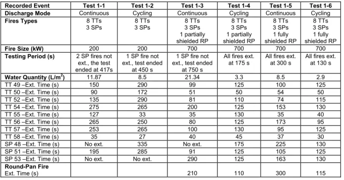
Table 1. The Performance of Continuous and Cycling Water Mist Discharges in the Empty Enclosure
Recorded Event Test 1-1 Test 1-2 Test 1-3 Test 1-4 Test 1-5 Test 1-6 Discharge Mode Continuous Cycling Continuous Cycling Continuous Cycling Fires Types 8 TTs 3 SPs 8 TTs 3 SPs 8 TTs 3 SPs 1 partially shielded RP 8 TTs 3 SPs 1 partially shielded RP 8 TTs 3 SPs 1 fully shielded RP 8 TTs 3 SPs 1 fully shielded RP Fire Size (kW) 200 200 700 700 700 700
Testing Period (s) 2 SP fires not ext., the test ended at 417s
1 SP fire not ext., test ended
at 450 s
1 SP fire not ext., test ended
at 750 s
All fires ext. at 175 s
All fires ext. at 300 s
All fires ext. at 130 s Water Quantity (L/m2) 11.87 8.5 21.34 3.3 8.5 2.9 TT 49 –Ext. Time (s) 150 290 99 125 100 125 TT 50 –Ext. Time (s) 90 172 51 50 54 50 TT 52 –Ext. Time (s) 135 290 81 110 74 115 TT 54 –Ext. Time (s) 275 265 200 125 153 130 TT 55 –Ext. Time (s) 127 33 35 130 35 40 TT 56 –Ext. Time (s) 265 250 80 125 173 95 TT 57 –Ext. Time (s) 253 265 100 130 95 125 TT 58 –Ext. Time (s) 35 27 40 45 37 30
SP 48 –Ext. Time (s) No ext. 335 No ext. 175 225 130
SP 51 –Ext. Time (s) 195 285 91 125 105 125
SP 53 –Ext. Time (s) No ext. No ext. 290 125 163 130
Round-Pan Fire
Table 2: The Performance of Continuous and Cycling Water Mist Discharges in a Simulated Machinery Space without Ventilation
Recorded Event Test 2-1 Test 2-2 Test 2-3 Test 2-4 Test 2-5 Test 2-6 Discharge Mode Continuous Cycling Continuous Cycling Continuous Cycling Fires Types 3 SPs 3 SPs 1 shielded
round fire 1 shielded round fire 1 shielded spray fire 1 shielded spray fire Fire Size (kW) 150 150 500 500 520 520
Ext. Time (s) No ext., 960 s discharge period
180 114 115 113 130
Water Quantity (L/m2)
28.1 3.5 3.1 2.1 3.1 2.7
Table 3: The Performance of Continuous and Cycling Water Mist Discharges in a Simulated Machinery Space with Ventilation
Recorded Event Test 3-1 Test 3-2 Test 3-3 Test 3-4 Test 3-5 Test 3-6 Discharge Mode Continuous Cycling Continuous Cycling Continuous Cycling Ventilation Door open Door open Door open, fan
running Door open, fan running Door open, fan running Door open, fan running Fires Types 1 shielded
round fire 1 shielded round fire 1 shielded round fire 1 shielded round fire 1 shielded spray fire 1 shielded spray fire Fire Size (kW) 500 500 500 500 520 520
Ext. Time (s) 420 220 No ext., 630 s discharge period
168 510 227 Water Quantity
(L/m2)
Time (s) 0 30 60 90 120 150 180 210 240 270 300 330 360 390 Tem per at ure ( o C) 0 100 200 300 400 500 600 700 800 900 1000 No. 1 (2.73 m) No. 2 (1.83 m) No. 3 (0.93 m) No. 4 (0.48 m)
Figure 5: Temperature profile over the round-pan fire during Test 1-5 with the continuous discharge
Thermocouples Time (s) 0 30 60 90 120 150 180 210 240 270 300 Tem per at ure ( o C) 0 100 200 300 400 500 600 700 800 900 1000 No. 1 (2.73 m) No. 2 (1.83 m) No. 3 (0.93 m) No. 4 (0.48 m) on off on off on Thermocouples
Figure 6: Temperature profile over the round-pan fire during Test 1-6 with the cycling discharge
Time (s) 0 30 60 90 120 150 180 210 240 270 300 O2 Concent rat ion (% ) 15 16 17 18 19 20 21 22 continuous (Test 1-5) cycling (Test 1-6)
Figure 7: Room O2 concentrations using the continuous and cycling discharges for shielded fire suppression in an empty enclosure
Figure 8: Room O2 concentrations using the continuous and cycling discharges for shielded fire suppression in a simulated machinery space Discharge mode on off on off on Time (s) 0 30 60 90 120 150 180 210 240 270 300 O2 Conce n tr at io n ( % ) 16 17 18 19 20 21 22 continuous (Test 2-1) cycling (Test 2-2)
on off on off on off on off Discharge mode extinguishing
extinguishing
extinguishing
Time (s) 0 30 60 90 120 150 180 210 240 270 300 330 360 390 Tem per at ure ( o C) 0 25 50 75 100 125 150 175 200 225 250 275 No. 1 (2.90 m) No. 2 (2.35 m) No. 3 (1.80 m) No. 4 (1.25 m) No. 5 (0.70 m) No. 6 (0.15 m)
Figure 9: Room temperatures measured at thermocouple tree #3 during Test 1-5 with the continuous discharge
Thermocouples on off on off on
Thermocouples
Figure 10: Room temperatures measured at thermocouple tree #3 during Test 1-6 with the cycling discharge
Time (s) 0 30 60 90 120 150 180 210 240 270 300 CO 2 Concen tr at io n ( % ) 0.0 0.5 1.0 1.5 2.0 2.5 3.0 3.5 4.0 2.8 m (cycling) 1.5 m (cycling) 2.8 m (continuous) 1.5 m (continuous)
Figure 11: Room CO2 concentrations using the continuous and cycling discharges in Tests 1-5 and 1-6
Figure 12: Room temperatures in Test 3-5 using the continuous discharge under forced ventilation conditions
Sampling port on off on off on Time (s) 0 30 60 90 120 150 180 210 240 270 300 Tem per at ur e ( o C) 0 25 50 75 100 125 150 175 200 225 250 275 No. 1 (2.90 m) No. 2 (2.30 m) No. 3 (1.80 m) No. 4 (1.25 m) No. 5 (0.70 m) No. 6 (0.15 m) Time (s) 0 50 100 150 200 250 300 350 400 450 500 550 600 Tem per at ure ( o C) 0 10 20 30 40 50 60 70 80 90 100 No. 1 (2.90 m) No. 2 (2.35 m) No. 3 (1.80 m) No. 4 (1.25 m) No. 5 (0.70 m) No. 6 (0.15 m) Thermocouples
Figure 14: Room O2 concentrations using the continuous and cycling discharges under forced ventilation conditions
Figure 13: Room temperatures using the cycling discharge in Test 3-6 under forced ventilation conditions
Time (s) 0 30 60 90 120 150 180 210 240 270 300 330 360 Tem per at ur e ( oC) 0 20 40 60 80 100 120 140 160 No. 1 (2.90 m) No. 2 (2.35 m) No. 3 (1.80 m) No. 4 (1.25 m) No. 5 (0.70 m) No. 6 (0.15 m) Time (s) 0 30 60 90 120 150 180 210 240 270 300 330 360 O2 co ncent ra tion (% ) 15 16 17 18 19 20 21 22 continuous (Test 3-5) cycling (Test 3-6)
on off on off on off off off Thermocouples
on off on off on off on off on off Discharge mode extinguishing on on Time (s) 0 30 60 90 120 150 180 210 240 270 300 O2 Concen tr at io n ( % ) 15 16 17 18 19 20 21 22 700 kW 200 kW
Figure 15: Room O2 concentrations using the same cycling discharge frequency but different fire sizestwo
Fire Size Time (s) 0 30 60 90 120 150 180 210 240 270 300 T em p era tur e ( o C) 0 25 50 75 100 125 150 175 200 225 250 275 700 kW (2.90 m) 700 kW (2.30 m) 200 kW (2.90 m) 200 kW (2.30 m)
Figure 16: Room temperatures measured at thermocouple tree #3 using the same discharge frequency but with two
Thermocouples