https://doi.org/10.4224/40001837
Vous avez des questions? Nous pouvons vous aider. Pour communiquer directement avec un auteur, consultez la première page de la revue dans laquelle son article a été publié afin de trouver ses coordonnées. Si vous n’arrivez pas à les repérer, communiquez avec nous à [email protected].
Questions? Contact the NRC Publications Archive team at
[email protected]. If you wish to email the authors directly, please see the first page of the publication for their contact information.
https://publications-cnrc.canada.ca/fra/droits
L’accès à ce site Web et l’utilisation de son contenu sont assujettis aux conditions présentées dans le site LISEZ CES CONDITIONS ATTENTIVEMENT AVANT D’UTILISER CE SITE WEB.
READ THESE TERMS AND CONDITIONS CAREFULLY BEFORE USING THIS WEBSITE. https://nrc-publications.canada.ca/eng/copyright
NRC Publications Archive Record / Notice des Archives des publications du CNRC :
https://nrc-publications.canada.ca/eng/view/object/?id=a4b60f11-9330-413e-9a20-d7e8cbe079a1
https://publications-cnrc.canada.ca/fra/voir/objet/?id=a4b60f11-9330-413e-9a20-d7e8cbe079a1
NRC Publications Archive
Archives des publications du CNRC
For the publisher’s version, please access the DOI link below./ Pour consulter la version de l’éditeur, utilisez le lien DOI ci-dessous.
Access and use of this website and the material on it are subject to the Terms and Conditions set forth at
Review of 20 years of range sensor development
Council Canada Institute for Information Technology de recherches Canada Institut de technologie de l'information
Review of 20 Years of Range Sensor Development *
Blais, F.
January 2004
* published in the Journal of Electronic Imaging, 13(1): 231-240. January 2004. NRC 46531.
Copyright 2004 by
National Research Council of Canada
Permission is granted to quote short excerpts and to reproduce figures and tables from this report, provided that the source of such material is fully acknowledged.
Review of 20 years of range sensor development
Franc¸ois Blais
National Research Council Canada Institute for Information Technology
Ottawa, Ontario, K1A-0R6 Canada
E-mail: [email protected]
Abstract. We review 20 years of development in the field of 3-D laser imaging. An overview of 3-D digitizing techniques is presented with an emphasis on commercial techniques and systems currently available. It covers some of the most important methods that have been developed, both at the National Research Council of Canada (NRC) and elsewhere, with a focus on commercial systems that are considered good representations of the key technologies that have survived the test of years. © 2004 SPIE and IS&T.
[DOI: 10.1117/1.1631921]
1 Introduction
The past 20 years have seen enormous progress in the de-velopment of noncontact optical surface digitizers. The large number of companies that are now offering commer-cial 3-D range sensor systems shows that 3-D-based tech-nology has successfully passed the initial stage of research curiosities in laboratories of the 1980s and the numerous demonstrations of applications of the 1990s. Powerful al-gorithms and data processing software gradually comple-ments 3-D sensing, demonstrating that dimensional appli-cations are often better performed using reliable 3-D images than 2-D. However, 3-D vision systems are still in their infant stages when compared to their equivalent 2-D counterparts. In general, 3-D is still several years behind in terms of image quality, rendering, and ease of use.
During the last decade, much research has been pub-lished describing ‘‘novel’’ range sensors. Among this re-search are truly innovative works in the development of ranging methods, and a large majority brings important key ingredients that refine the knowledge in the field, but un-fortunately many are also reinventing the subject. Further-more, specialization of research and the presumption that software can solve all the problems often creates erroneous expectations based on extrapolations that break the laws of physics.
Various methods for acquiring range images were sur-veyed by Jarvis in 1983.1Besl in 1986 presented an over-view of different range measurement techniques and com-mercial sensors.2 At the time, the number of commercial systems was much smaller than today. He also proposed a
merit function to compare sensor performances. More re-cently, Tiziani3 and Chen, Brown, and Song4 presented comprehensive surveys focusing on a few techniques used mostly for object modeling, and although 3-D object mod-eling applications are today quickly growing, they are only one facet of 3-D sensing. This work presents this vast sub-ject from a more industry-oriented perspective that includes applications ranging from inspection to 3-D object model-ing.
The aim of this work is to quickly review the past 20 years of research and work in the field. To avoid the possi-bility of drawing historically false conclusions, it focuses in part with research that was done at the National Research Council of Canada ~NRC! and on the evolution of key tech-nologies and components that were used to build range sen-sors. This evolution is not unique to NRC and similar con-clusions can be drawn for other groups. Furthermore, it helps explain some of the current industrial trends. Consid-ering that prototypes usually take 5 to 10 years from the initial research laboratory to commercialization, while cremental innovations are implemented more quickly, in-dustrial systems are therefore a good indicative of past and recent work.
Although far from being complete, the tables include descriptions of nearly 80 companies, most of them offering many variants of 3-D range camera systems. Obviously, not all the companies can be listed, and this selection was based on a combination of innovation, design particulari-ties, demonstration of ranging methods, or specific applica-tions. The appendices contain more technical information to support the comments and conclusions drawn.
2 Range Sensor Development
The practical development of 3-D laser range sensors closely follows the availability of new electronic compo-nents and electro-optical emerging technologies. The prin-ciple of range measurement based on triangulation is cen-turies old. This principle was demonstrated by the Greeks for navigation and by astronomers. Erastothenes used the shadow created by the sun to measure the circumference of the earth, with impressive results considering this was done more than 2000 years ago. During the two world wars, intensive use of passive optical range finders by the mili-tary was common practice. During the 1970s and beginning of the 1980s, the availability of low-cost light position and Paper 03033 received Mar. 3, 2003; revised manuscript received Aug. 22, 2003;
accepted for publication Sep. 4, 2003. 1017-9909/2004/$15.00 © 2004 SPIE and IS&T.
other electro-optical devices, and the introduction of the microcomputer, made possible the development of cost-effective automated range sensor systems for industrial ap-plications. At first, position sensitive devices were mostly analog in nature. For example, the lateral effect photodiode ~LEP! and Vidicon-type cameras were used to convert op-tical information to an electrical signal that was then pro-cessed to extract range information. These technologies were difficult to use and quasi-impossible to calibrate, lim-ited by inaccuracies and drifts in the electronics.
2.1 Single Point and Laser Scanners
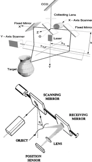
During the 1970s, a few research laboratories were already involved in 3-D. The plane-of-light and pattern projection methods were known practice. In 1983, Jarvis1published a survey of some of these works. In the early 1980s, the NRC initiated a research program in 3-D, focusing on the devel-opment of high-accuracy triangulation-based 3-D range sensors.5 The synchronized laser scanner principles using fast scanning mirrors, as shown in Fig. 1.6,7 were intro-duced by the NRC and other laboratories. The advantage of synchronizing the optical detector with laser projection
en-abled the use of long focal length lens zoom configurations ~see Appendix A in Sec. 5!. The extra cost of using me-chanical scanners was minimal compared with a tenfold increase in performances. Gas lasers were used and acqui-sition rates to 200 kHz were obtained, and later pushed to 10 MHz video-rates8 with newer LEPs.9 Other research with different optical principles and scanning methods pro-duced similar quasi-video rate systems10still used today for the automatic inspection of electronics packaging, and sol-dering paste ~e.g., Sec. 3.1!.
During the following years, several concepts of detec-tors using geometrically shaped LEP or specially designed masks were presented. The introduction of the CCD array created an important breakthrough in 3-D active triangulation-based range sensors. The NRC’s first proto-type used a linear 2048-element CCD from Fairchild. An all-digital solution to the laser position measurement was possible, bringing accuracy and stability to the range data. Although slower, CCD devices were much more accurate and stable.11–13When coupled with real-time subpixel digi-tal peak detection algorithms,12,14 range resolution in the order of 0.1% was obtained compared to 1% with analog detectors. Reduced acquisition speeds also allowed the use of slower but more accurate galvanometer-based scanning devices rather than fast polygonal rotating mirrors.
Faster and larger CCD pixel arrays, initially developed for spectroscopy applications ~e.g., Reticon!, were commer-cially available. Coupled with better processing, these de-vices pushed the range accuracy to 0.01%, which conse-quently created the need for new and more accurate galvanometers and control to obtain 0.01% in pointing precision.15,16Laser position detection is now mostly lim-ited by physical and optical limits17,18and the performances of the sensors quickly exceeded the range of the merit func-tion that was proposed by Besl.2,19 Other prototypes were developed to support eye-safe lasers ~1.5mm!, initially us-ing optically pumped fiber lasers and later with laser diodes;20time-of-flight ~TOF! measurements; and color de-tection with the addition of a white laser source ~RGB!, color separation optics, and multiple peak position and color intensity detection.21
Several triangulation principles, devices, and techniques were published mostly during the 1980s: lateral and longi-tudinal synchronization, electroacoustic and piezodeflec-tors, micromirrors, prisms, and holographic scanners.22 Re-search also focused on algorithms for the detection of laser spot position,14new linear detectors, parallel arrays, detec-tors with masks, the use of the Schleimpflug condition, and other optical and numerical methods to increase accuracy and to reduce laser speckle noise while preserving the over-all shape information.
Today, single-point 3-D laser scanners still offer many technical advantages. The whole CCD length can be opti-mized for a given volume of measurement, resulting in higher resolution and accuracy than slit scanners. Laser modulation and control can be optimized on a per-voxel basis to increase the SNR of the returned signal,19 a must for metallic and other reflective surfaces. The cost is usu-ally higher than slit scanners because of the use of scanning mechanical devices and specialized components, such as galvanometers and large pixel linear CCDs.
Fig. 1 Single-point laser scanning using longitudinal
synchroniza-tion (top) and lateral synchronizasynchroniza-tion (bottom). Range magnificasynchroniza-tion and immunity to ambient light is obtained without compromising the field of view of the 3-D camera.
Figures 1– 4 are examples of single-point triangulation sensor configurations. These figures were produced using a professional optical lens design and ray-tracing program, and show the basic principles as well as the subtleties of image formation and defocusing. The basic triangulation principle is shown in Fig. 2, where a narrow laser beam is projected on the surface of an object and imaged at differ-ent positions on the CCD, depending on range. A closeup shows how the Schleimpflug angle provides optimum im-age focusing on the CCD, independent of range. The tilt of the detector guarantees that the light point projected on the
object will always be imaged in focus. The advantage of using a laser lies in the very large depth of focus defined by Gaussian beam propagation equations and high power in small packages at the compromise of increased laser speckle noise ~more later in Sec. 2.3 and Appendix B in Sec. 6!.
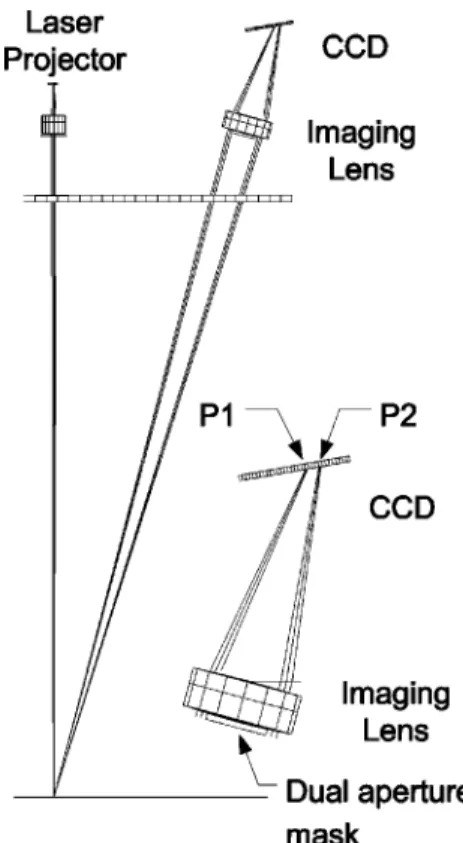
The dual-view principle of Fig. 3 serves two purposes: the redundancy in the measurements improves the accuracy of the sensor by a factor of& and at the same time vali-dates ranging; and an image of the laser will be symmetric on the two CCDs while an outlier ~e.g., specular reflection of sun interference! will be asymmetric. The Biris principle of Fig. 4 provides equivalent advantages using only one CCD. A dual-aperture mask ~Bi-Iris! inserted next to the diaphragm of the lens creates two spots P1 and P2 on the CCD detector and a unique peak-position/peak separation relationship. Figure 1 shows two examples of synchronized scanning that use galvanometers and mirrors to sweep a single-point laser beam on the surface of an object. The imaging and projection optical paths are mechanically syn-chronized.
2.2 Slit Scanner
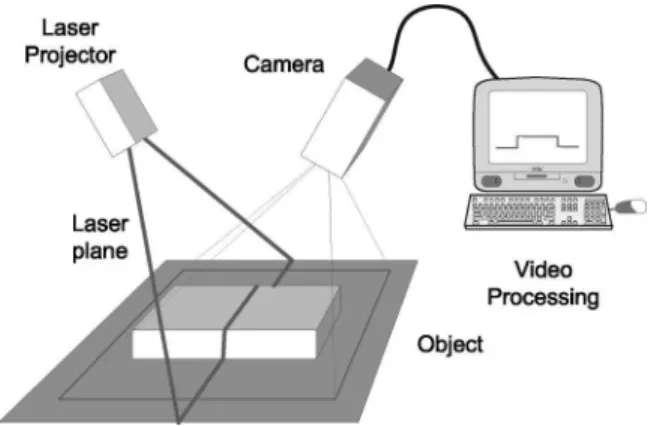
The slit scanner is by far the most widely used triangulation-based 3-D laser camera because of its optical and mechanical simplicity and cost. The slit scanner is a natural extension of the linear single-point detector, allow-ing the projection of a laser line and the simultaneous de-tection of a complete profile of points in a single video frame. Rather than using a multitude of single-point probes or costly mechanical scanning devices ~galvanometers, po-lygonal scanners!, a laser line is projected on the object and
Fig. 2 Basic triangulation principle; the position of the image on the
CCD is directly related to the range. Large depth of focus is obtained using lasers and the Schleimpflug condition.
Fig. 3 Dual-view triangulation creates measurement redundancies
that increase accuracy and remove erroneous reading.
Fig. 4 A dual-aperture mask produces similar advantages without
requiring a second detector.
imaged at an angle. The deformation of the profile is a direct function of range, as shown in Fig. 5.
The introduction of CCD arrays in the early 1980s elimi-nated the inherent problems associated with tubes, and the Vidicon camera became quickly obsolete. Low-cost laser diodes in the late 1980s eliminated the need for gas lasers and allowed the creation of very compact sensor heads. Recently, the introduction of a low-cost complementary metal-oxide semiconductor ~CMOS! detector that incorpo-rates digital conversion and on-chip processing, high-speed digital bus interface, and powerful computers further re-moves the need for dedicated acquisition frame grabbers and specialized electronics.
The main inconvenience of a slit scanner is the compro-mise between the field of view and depth resolution ~see Appendix A in Sec. 5!.19Field of views in the order of 20 to 30 deg are usually published. To increase the field of view, anamorphic optical designs were introduced; cylindrical lens add-ons gave an interesting 60-deg field of view.23The second disadvantage associated with slit scanners is their relatively poor immunity to ambient light. Optical signal-to-noise ratio is reduced because of the spread of the laser power along the projected line, and because the sensor must image the whole scene. Strong ambient light will perturb the measurements even if narrow-band optical interference filters are used. Although not that critical for indoor envi-ronments, this is particularly important for outdoors, and some robotics applications.24 Several methods have been proposed, such as dark frame subtraction and range redun-dancy using optical principles, such as those illustrated in Figs. 3 and 4. These partial solutions do not eliminate the problem of detector saturation.
Cost reductions are directly associated with the introduc-tion of smaller detectors and the possibility of integrating more pixels and more functionality on a single IC. From the 1-in. Vidicon-type detector, the 2/3- and 1/2-in. CCD, the newer CMOS arrays are 1/3-in. and now 1/4-in. in size. Although lateral resolution increases because of the larger number of pixels, overall optical and range performances are expected to remain relatively the same or even decrease with these new CMOS detectors. Assuming perfect optics, speckle noise and optical resolution are physical limits that were already reached with the 2/3-in. CCD ~see Appendix
A in Sec. 5!. These physical limits are today the main limi-tations, and major new innovations must be researched.
Manufacturers must often sacrifice many of these ideal considerations for cost reasons. For example, the Schle-impflug condition is rarely used with slit scanners, and al-though this dramatically reduces the depth of focus, appli-cations such as inspection of surface defects that do not require large depth will not suffer. However, because it does not show in the manufacturer specifications, many us-ers are often surprised when testing their large volume sys-tem, wondering why the system did not performed as ex-pected.
2.3 Pattern Projection and Moire´
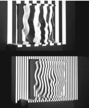
Pattern techniques use multiple stripes or patterns projected simultaneously on the object, as seen in Fig. 6, rather than mechanically scanning a single laser line of point on the scene and processing independent range profiles.25–27
The basic moire´ principle uses two precisely matched pairs of gratings, the projected light is spatially amplitude modulated by the grating, and the camera grating demodu-lates the viewed pattern and creates interference fringes whose phases are proportional to range.28 Projective moire´ is considered a triangulation-based method and follows the mathematics presented in Appendix A in Sec. 5. Other methods use only the projective moire´ pattern and software to demodulate the signal.29 Moire´ patterns are most useful with objects having relatively large flat surfaces and small depth variations. To avoid the problem of phase discrimi-nation of moire´ patterns ~phase measurement multiples of
p!, different methods have been proposed, the most com-mon being surface continuity algorithms.
Other methods propose the use of a projective pattern and the detection of the same pattern from multiple views using stereoscopic systems.30 To use redundancy in the range measurement created by a double-aperture mask to validate detection when multiple laser line profiles are projected,31,32the use of a circular mask and projection of a pattern of dots31,33 are other elegant solutions. These ap-Fig. 5 Slit scanners are a direction extension of the basic
triangu-lation principle of Fig. 2. Simplicity of the design results in a com-promise between accuracy and field of view (see Appendix A in Sec. 5).
Fig. 6 LCD pattern projection systems create a magnified image of
the projector pixel on the object, limiting lateral resolution but pro-viding simultaneous measurements in a single video frame. Depth volume is limited by the defocusing of both projection and detection.
proaches are commercially available from ShapeGrabber and Wolfbeck ~Sec. 3.2!. The Virtual 3D Tech system uses a multiple-view camera system and algorithms to detect the correlation between speckle-generated images.34
The sequential projection of encoded patterns is another elegant way of dealing with range ~or phase shift! ambiguities.35 The most popular methods for pattern pro-jection use binary coded or phases shift fringe patterns.36 – 40 Gray-code binary images use multiple frames with in-creased resolution ~bits! to encode a pixel on the CCD with its corresponding range, as shown in Fig. 7. Subpixel reso-lution is obtained by detecting the edge transitions in the highest resolution image. Steinbichler41 commercializes sensors based on this technique. Other methods use sinu-soidal phase encoding to measure range.42,43 Using this method, it can be demonstrated that three video frames are sufficient to calculate the relative phase of the sinusoidal pattern, although in practice more frames are used to in-crease accuracy. Coded pattern methods are also very popu-lar because of the availability of low-cost projectors and a
full 3-D volume can be acquired quickly in just a few video frames.
The use of incoherent light reduces speckle noise asso-ciated with lasers and consequently provides better surface smoothness. However, the depth of view is smaller when compared to laser strip scanners, as shown in Fig. 7. Abso-lute accuracy for an equivalent 3-D volume ~and not only for a surface! will be relatively smaller than its laser coun-terparts. As illustrated in Fig. 7, important technical issues have to be addressed, especially the defocus of the pro-jected pattern due to the fact that a larger projector lens is needed to collect as much light as possible from the light source, the spatial resolution of the pattern, smaller depth of focus of the imaging lens, and reduced dynamic range in intensity.
2.4 Time-of-Flight Systems
For large structures, time-of-flight ~TOF! 3-D scanners are by far the preferred choice for measurements at longer ranges. Range accuracy is relatively constant for the whole volume of measurement. Because these systems require de-tection of the time light propagates through air, measure-ments will be affected mostly by drifts and jitter in the electronics ~see Appendix B in Sec. 6!. Different methods have been proposed in the research community: pulse, am-plitude modulation, frequency modulation, hybrid detec-tion, and self-mixing diodes.44 We describe only the most popular methods.
A pulse TOF detects the time a laser pulse is reflected back to the receiving detector, usually an avalanche photo-diode. Picosecond resolution implies very sensitive elec-tronics with high bandwidth, constant group delays, and excellent thermal stability. To reduce noise, multiple pulses are averaged, and resolution in the order of 0.5 to 1 cm is now standard. Different methods have also been proposed to create a reference signal used to autocalibrate the system. High-frequency bandwidth in the electronics is needed to amplify the large-frequency spectrum associated with pulses. Amplitude modulation of the optical carrier has been proposed, where range is measured from the phase variation between the transmitted and received signal. The electronics are a little more complex than pulse TOF, but the reduced bandwidth provides better range resolution in the order of 3 to 5 mm. Other frequency modulation tech-niques ~e.g., FM! are also used, and as expected, excellent
Table 1 Interferometry. Legend for all tables is as follows: T5Triangulation, TOF5Time of flight, M
5moire´, St5stereo, Sil5shape from silhouette, Int5interferometry, P5pattern projection, Ph 5photogrammetry, and A5aperture/mask.
Company Type Description Range Accuracy Atos (www.atos-online.de) Int White light interferometer and
confocal systems
0.02 nm Optimet-Conoscan
(www.optimet.com)
Int Conoscopic holography 0.6–180 mm
2–50mm Optonor (www.optonor.com) Int Projective microscopy moire´ and
interferometry MiiC-Opton Co. Ltd.
(www.opton.co.jp)
Int Moire´ projection 10–20 mm
10–25mm Zygo (www.zygo.com) Int White light interferometer 150mm 0.1 nm
Fig. 7 Binary coded pattern projection; a 3-D image can be
ac-quired in a few frames.
range accuracy have been measured; submillimeter range resolutions are reported ~see Table 5!.
Other techniques have been proposed that fall in the gray region between TOF and interferometry.45,46Tables 1 and 2 show examples of commercial systems that use modulation of the light wavelength itself rather than a car-rier. Other interferometrics methods have also been devel-oped, such as optical wavefront propagation,47,48 light-in-flight interferometry,49,50 holography,51 and single photon counting.52,53
3 Commercial Systems
Cost is the major concern for the widespread use of 3-D technology. Powerful ranging techniques and many compa-nies failed commercially simply because they were unable to compete or to market their products, even if, in many cases, their products were technically far superior. 3-D technology is still in the early innovators stage of the tech-nology adoption life cycle.54 Sarcastically, the increasing number of patent infringement lawsuits is another indirect indicator of a growing sector of our economy. The tables list companies that, at the time of writing, were still active in 3-D. These companies are offering products based on the principles described in this work.
3.1 Single-Point Probes and Laser Scanners
Specialized applications that require speed, high immunity to ambient light, or increased depth will benefit from single-point triangulation-based laser scanners. For ex-ample, rather than developing a unique general-purpose scanner solution, LMI offers a very large inventory of single-point probes and slit scanners that can be integrated into dedicated inspection systems. A wide range of indus-trial 3-D machine vision solutions under several brand names is offered to industrial sectors such as forestry, met-allurgy, automotive, electronics, robot guidance, road, and manufacturing. LMI is the merging of four industrial play-ers in the 3-D machine vision industry: Selcom ~Sweden!, Dynamic Control Systems ~Canada!, Sensors-95 ~Holland!, and Diffracto ~Canada!.
RVSI Electronics is an example of a market strategy to provide a vertically integrated line of products for a key industrial sector. They offer 2-D and 3-D vision systems with a focus toward the inspection of semiconductor pack-ages and the semiconductor industry. The major distinctive
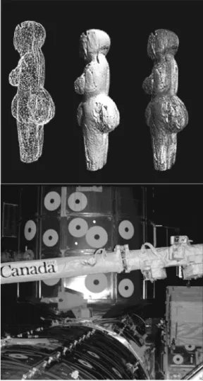
characteristic of their systems is speed, approximately 5 million 3-D points per second with resolution to 2.25mm. Servo-Robot is specialized in automatic welding sys-tems and uses the autosynchronized laser scanner principle to obtain high-accuracy range images. Figure 8 shows an example of a 3-D color object acquired with the NRC sys-tem. The autosynchronized scanner is coupled to an RGB laser to create high-resolution color textured 3-D objects. Because color is perfectly registered with shape, high-resolution color textured objects are measured without the ambiguity and problems of registration created by project-ing the color texture acquired from a separate camera. Arius 3-D commercializes its own proprietary implementation based on a variation of this principle.
Neptec has recently developed, in collaboration with NRC, an eye-safe scanning laser range camera, based on the autosynchronized principle, to the stringent require-ments set by NASA for use aboard the space shuttle. The system was tested on-board the space shuttle Discovery in August 2001, and more recently, during the investigation of Columbia’s disaster. The system can acquire volumes of up to 10 m in triangulation mode, as shown in Fig. 8. High immunity to ambient light and increase depth is obtained.
The Digibotic system integrates both rotation and trans-lation with a high-accuracy, single-point 3-D laser probe to automatically scan an object. Two triangulation detectors, located on either side of the laser projector, are mechani-cally moved until the laser point on the object is aligned with the two optical heads. Scanning is implemented using mechanical translation ~two-axis! of the optical probe and rotation of the object. Accuracy is mostly limited by me-chanical constraints; long focal length lenses are used to increase accuracy.
For very high accuracies using triangulation, Atos offers a white light confocal profiler that consists of a confocal microscopy setup and a noncontact probe. The probe is located on a computer-driven precision table and the con-focal unit is mechanically moved in z. Because of the very narrow depth of focus of a confocal microscope, high range resolution ~0.1 mm! is obtained. Nanofocus is another ex-ample of a confocal microscopic-based laser system. 3.2 Slit Scanners
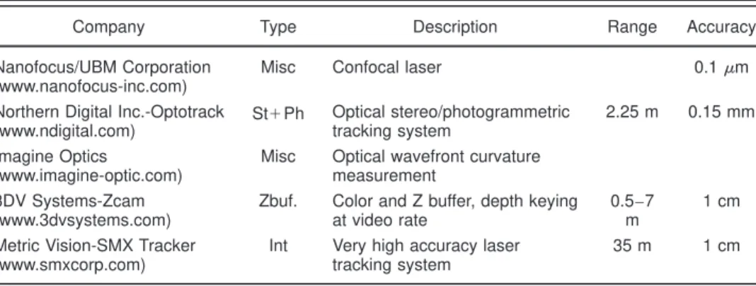
Slit scanners are by far the most popular triangulation-based systems because of their low cost. Quoted precisions are relatively similar between manufacturers, because slit Table 2 Others.
Company Type Description Range Accuracy Nanofocus/UBM Corporation
(www.nanofocus-inc.com)
Misc Confocal laser 0.1mm Northern Digital Inc.-Optotrack
(www.ndigital.com) St1Ph Optical stereo/photogrammetric tracking system 2.25 m 0.15 mm Imagine Optics (www.imagine-optic.com)
Misc Optical wavefront curvature measurement
3DV Systems-Zcam (www.3dvsystems.com)
Zbuf. Color and Z buffer, depth keying at video rate
0.5–7 m
1 cm Metric Vision-SMX Tracker
(www.smxcorp.com)
Int Very high accuracy laser tracking system
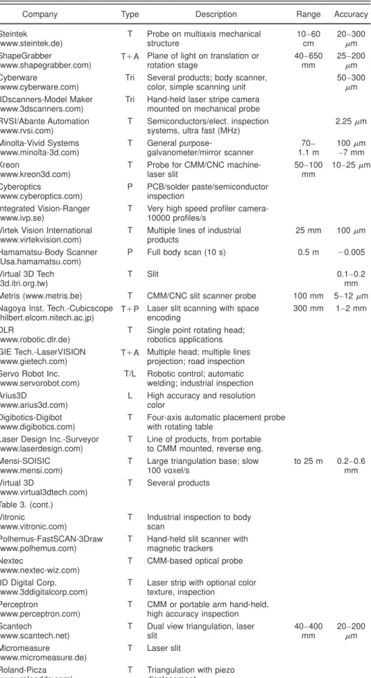
Table 3 Triangulation with lasers.
Company Type Description Range Accuracy Steintek
(www.steintek.de)
T Probe on multiaxis mechanical structure 10–60 cm 20–300 mm ShapeGrabber
(www.shapegrabber.com) T1A Plane of light on translation orrotation stage
40–650 mm 25–200 mm Cyberware (www.cyberware.com)
Tri Several products; body scanner, color, simple scanning unit
50–300
mm 3Dscanners-Model Maker
(www.3dscanners.com)
Tri Hand-held laser stripe camera mounted on mechanical probe RVSI/Abante Automation
(www.rvsi.com)
T Semiconductors/elect. inspection systems, ultra fast (MHz)
2.25mm Minolta-Vivid Systems (www.minolta-3d.com) T General purpose-galvanometer/mirror scanner 70– 1.1 m 100mm –7 mm Kreon (www.kreon3d.com)
T Probe for CMM/CNC machine-laser slit 50–100 mm 10–25mm Cyberoptics (www.cyberoptics.com) P PCB/solder paste/semiconductor inspection Integrated Vision-Ranger (www.ivp.se)
T Very high speed profiler camera-10000 profiles/s
Virtek Vision International (www.virtekvision.com)
T Multiple lines of industrial products
25 mm 100mm Hamamatsu-Body Scanner
(Usa.hamamatsu.com)
P Full body scan (10 s) 0.5 m 20.005 Virtual 3D Tech
(3d.itri.org.tw)
T Slit 0.1–0.2
mm Metris (www.metris.be) T CMM/CNC slit scanner probe 100 mm 5–12mm Nagoya Inst. Tech.-Cubicscope
(hilbert.elcom.nitech.ac.jp) T1P Laser slit scanning with spaceencoding
300 mm 1–2 mm DLR
(www.robotic.dlr.de)
T Single point rotating head; robotics applications GIE Tech.-LaserVISION
(www.gietech.com) T1A Multiple head; multiple linesprojection; road inspection Servo Robot Inc.
(www.servorobot.com)
T/L Robotic control; automatic welding; industrial inspection Arius3D
(www.arius3d.com)
L High accuracy and resolution color
Digibotics-Digibot (www.digibotics.com)
T Four-axis automatic placement probe with rotating table
Laser Design Inc.-Surveyor (www.laserdesign.com)
T Line of products, from portable to CMM mounted, reverse eng. Mensi-SOISIC
(www.mensi.com)
T Large triangulation base; slow 100 voxel/s to 25 m 0.2–0.6 mm Virtual 3D (www.virtual3dtech.com) T Several products Table 3. (cont.) Vitronic (www.vitronic.com)
T Industrial inspection to body scan
Polhemus-FastSCAN-3Draw (www.polhemus.com)
T Hand-held slit scanner with magnetic trackers
Nextec
(www.nextec-wiz.com)
T CMM-based optical probe 3D Digital Corp.
(www.3ddigitalcorp.com)
T Laser strip with optional color texture, inspection
Perceptron
(www.perceptron.com)
T CMM or portable arm hand-held, high accuracy inspection Scantech
(www.scantech.net)
T Dual view triangulation, laser slit 40–400 mm 20–200 mm Micromeasure (www.micromeasure.de) T Laser slit Roland-Picza (www.rolanddg.com)
T Triangulation with piezo displacement
scanners share the same optical principle and similar com-ponents ~e.g., 1/2-in. CMOS detector and laser diodes!. Im-age resolution is also relatively equivalent between two-competing systems. Accuracy and stability of a
well-engineered mechanical head that uses composite material and good quality lenses rather than some inexpensive ther-mally unstable plastic material of a poor design is more difficult to assess. Comparing systems based solely on their Table 3 Continued.
Company Type Description Range Accuracy Neptec
(www.neptec.com)
T/L Space, industrial, mining, autosynchronized laser scanning Steinbichler Optotechnik-Comet
(www.steinbichler.de)
T Optical tracking hand-held slit scanner
83 mm 30mm Wolfbeck
(www.wolfbeck.com)
A Circular aperture triangulation probe
Dipix (www.dipix.com) T Online inspection food industry LMI Technologies
(www.lmint.com)
T Over 40 products: elect., inspection, manufacturing, forest Acuity Research-AR600
(www.acuityresearch.com)
T Probe up to 0.5 m
0.10% Taicaan (www.taicaan.com) T Single probe with translation 10 mm 2mm Steintek-3D-SCAN
(www.steintek.de)
T Triangulation based, laser slit 100–600 mm
20–300
mm
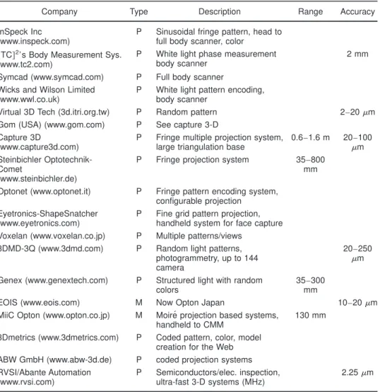
Table 4 Triangulation with pattern projection.
Company Type Description Range Accuracy InSpeck Inc
(www.inspeck.com)
P Sinusoidal fringe pattern, head to full body scanner, color
@TC#2’s Body Measurement Sys.
(www.tc2.com)
P White light phase measurement body scanner
2 mm Symcad (www.symcad.com) P Full body scanner
Wicks and Wilson Limited (www.wwl.co.uk)
P White light pattern encoding, body scanner
Virtual 3D Tech (3d.itri.org.tw) P Random pattern 2–20mm Gom (USA) (www.gom.com) P See capture 3-D
Capture 3D
(www.capture3d.com)
P Fringe multiple projection system, large triangulation base
0.6–1.6 m 20–100
mm Steinbichler
Optotechnik-Comet
(www.steinbichler.de)
P Fringe projection system 35–800 mm Optonet (www.optonet.it) P Fringe pattern encoding system,
configurable projection Eyetronics-ShapeSnatcher
(www.eyetronics.com)
P Fine grid pattern projection, handheld system for face capture Voxelan (www.voxelan.co.jp) P Multiple patterns/views
3DMD-3Q (www.3dmd.com) P Random light patterns, photogrammetry, up to 144 camera
20–250
mm Genex (www.genextech.com) P Structured light with random
colors
35–300 mm
EOIS (www.eois.com) M Now Opton Japan 10–20mm MiiC Opton (www.opton.co.jp) M Moire´ projection based systems,
handheld to CMM
130 mm 3Dmetrics (www.3dmetrics.com) P Coded pattern, color, model
creation for the Web ABW GmbH (www.abw-3d.de) P coded projection systems RVSI/Abante Automation
(www.rvsi.com)
P Semiconductors/elec. inspection, ultra-fast 3-D systems (MHz)
accuracies is also difficult, because the manufacturers will often quote partial performances of the optical head only, not the whole system ~see also Sec. 2.2!.
The volume of measurement of a slit scanner is rela-tively small compared to a single-point laser scanner ~Ap-pendix A in Sec. 5!. Because of their single profile, they are usually mounted on a mechanical motion stage to scan the object and create a complete 3-D model. Different alterna-tives are proposed:
• CMM or portable CMM ~telescopic arms! probes • linear or rotation stages
• optical or magnetic trackers.
Cyberware was one of the first companies to offer general-purpose 3-D range sensors. Today, they are mainly recog-nized for their full-body scanner for anthropometric mea-surements. This system includes four optical heads mounted on a long vertical translation stage to scan a com-plete human body in less than 17 s. A separate video sensor in each scanner head acquires color. Although color regis-tration and resolution is not as refined when compared to the color autosynchronized scanner, it is sufficient for the application. Body measurements are very popular today, as shown in the tables. Hamamatsu, for example, offers a body scanner system very similar to Cyberware.
ShapeGrabber has selected a combination of optical heads and mechanical scanning translation and rotation stages to create complete stand-alone, portable, general-purpose turnkey 3-D systems. They use different inter-changeable optical heads to cover different volume con-figurations, each head with a built-in intrinsic calibration.
The user only needs to scan a reference calibration target array to recalibrate the system when interchanging optical heads on either linear translation stages or tripod-mounted rotation stages. This approach offers a cost-effective solu-tion while preserving high accuracy and reliable measure-ments. The slit scanners are based on a combination of standard triangulation and the more robust Biris principle to provide high immunity to ambient light ~see Fig. 4 and Appendix A in Sec. 5!. Range accuracy between 25mm for small volumes to 200mm at 0.6 m are quoted.
ModelMaker from 3-D scanners also works on the prin-ciple of laser stripe triangulation. A lightweight noncontact scanning head is mounted on a portable CMM. Accuracy is not specified. Kreon manufactures similar compact triangu-lation heads that can be mounted on a robotic arm or CMM. A dual-view triangulation approach is used for reducing the problems associated with shadows ~Fig. 3!. As expected, accuracy of the probe is slightly better than single-view probes because of redundancy in the measurement. Speci-fied accuracies for the sensor head vary between 10 and 25
mm. Many other industrial companies are offering CMM-based sensors, mostly for the automotive industry: Metris, 3D Laser Scanning, Scantech, and Perceptron, to name a few. It is important to note that the inaccuracy of the CMM is not specified and must be added to these figures.
The Comet/T-Scan system from Steinbichler is a single, relatively compact hand-held laser slit scanner. The T-Scan uses a photogrammetry-based optical tracker to compute the exact global position of the sensor head in all 6-deg of freedom.
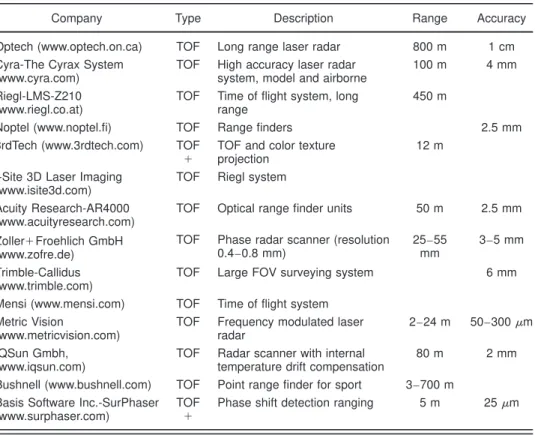
Neptec and Mensi are the only manufacturers we are aware that offer triangulation-based systems for larger vol-Table 5 Time of flight.
Company Type Description Range Accuracy Optech (www.optech.on.ca) TOF Long range laser radar 800 m 1 cm Cyra-The Cyrax System
(www.cyra.com)
TOF High accuracy laser radar system, model and airborne
100 m 4 mm Riegl-LMS-Z210
(www.riegl.co.at)
TOF Time of flight system, long range
450 m
Noptel (www.noptel.fi) TOF Range finders 2.5 mm 3rdTech (www.3rdtech.com) TOF
1
TOF and color texture projection
12 m I-Site 3D Laser Imaging
(www.isite3d.com)
TOF Riegl system Acuity Research-AR4000
(www.acuityresearch.com)
TOF Optical range finder units 50 m 2.5 mm Zoller1Froehlich GmbH
(www.zofre.de)
TOF Phase radar scanner (resolution 0.4–0.8 mm) 25–55 mm 3–5 mm Trimble-Callidus (www.trimble.com)
TOF Large FOV surveying system 6 mm Mensi (www.mensi.com) TOF Time of flight system
Metric Vision
(www.metricvision.com)
TOF Frequency modulated laser radar
2–24 m 50–300mm IQSun Gmbh,
(www.iqsun.com)
TOF Radar scanner with internal temperature drift compensation
80 m 2 mm Bushnell (www.bushnell.com) TOF Point range finder for sport 3–700 m
Basis Software Inc.-SurPhaser (www.surphaser.com)
TOF 1
Phase shift detection ranging 5 m 25mm
umes. Mensi developed a camera head that relies on a very large triangulation based d ~see Appendix A in Sec. 5!. The system mechanically adjusts the imaging parameters ~e.g., focus! resulting in a very slow acquisition rate ~100 Hz!. Neptec uses the synchronized principle ~Fig. 1! that allows long focal length f while preserving a large field of view and acquisition speed in the 10-kHz range. The mechanical head is much smaller, providing better mechanical stability. A lower cost commercial version of their space-qualified system is under development.
Recently, Minolta’s marketing plans and aggressive prices make them an important player in the general-purpose 3-D market. Their laser scanner is also based on laser scanning. Galvanometers are used to scan a laser line over the object, removing the need for external mechanical rotation or translation stages. The optical system does not use an autosynchronized principle, and as such requires re-focusing for a specific volume. A collinear color camera maps the color texture information on the geometry of the object. Only sensor resolution is quoted.
Finally, several examples of vertically integrated indus-trial 3-D solutions using slit scanners are commercially available. LMI also offers a wide variety of slit scanners for industrial applications. Other examples of vertically
inte-grated solutions are Dipix with products for on-line food inspection, and Servo-Robot for automatic industrial weld-ing. In the case of GIE, a six-head 3-D system, each with a 60-deg field of view and three laser lines simultaneously produces 18 3-D profiles on the surface of a road, produc-ing more than 23 million 3-D points per s. Real-time on-board 3-D data analysis provides dense inspection of road surfaces for vehicles traveling at speeds of 90 km/h.
3.3 Pattern Projection
Pattern projection systems offer the possibility of acquiring a full 3-D image without the need for a complex mechani-cal scanning apparatus ~Figs. 6 and 7!. Although the accu-racy for an equivalent depth of view will be comparatively smaller than a slit or laser point scanner, the use of inco-herent light removes the speckle noise associated with la-sers, resulting in smooth data and the possibility of acquir-ing color texture. This method is therefore ideal for human body measurements where absolute accuracy is not as im-portant as rapidly obtaining smooth surfaces ~e.g., Inspeck, TC2, Symca, Wicks and Wilson, and 3Dmd!.
For industrial inspection applications, Steinbichler Op-totechnik offers the Comet/Vario Zoom that uses white light binary fringe projection added to the possibility of using accurate photogrammetric reference measurements. The fringe projection system provides data accuracy to 20
mm over a surface of approximately 45335 mm. Range depth is not specified ~see also Sec. 2.3!. Optonet offers a similar single camera-projector system.
For body measurements, 3Dmetrics and Inspec use white light 3-D projection systems. 3Dmetrics uses a color-coded grid pattern, while Inspec selected a sinusoidal fringe pattern projection method. Genex uses a dual camera with a white light projector to obtain both range and color texture information at the same time. Several multihead configura-tions are available, from small to large volumes, that can cover the full human body. The 3D Tech system includes a stereoscopic dual-camera setup and a speckle generator. The speckle generator projects spots onto the surface of the target object, and two cameras take snapshots from their respective viewpoints. Algorithms establish the correlation of corresponding partitions on the two speckled images to compute the 3-D coordinates. The Atos system from GOM is another stereoscopic system, but fringes are projected onto the object surface, recorded by two CCD cameras.
The Cubicscope from Nagoya Institute of Technology is based on binary space encoding methods, but contrary to other systems, they use a modulated laser slit that is scanned over the surface of the object. The polygonal mir-ror has 12 faces and a servomotor at 1800 rpm drives it. Very fast modulation of the laser beam generates the binary pattern. Larger depth of field is possible because of the use of a laser beam at the compromise of some jitter and wobble associated with rotating mirrors.
Finally, EOIS specializes in geometrical projection moire´-type 3-D sensors with resolution typical of triangu-lation systems ~25mm!. Because a moire´ projector does not need the complexity of pattern projectors, a more compact CMM-based scanner head can be built. Range ambiguity, object surface discontinuities, and fringe counts are com-pensated by software.
Fig. 8 Applications of 3-D sensor range from high-accuracy 3-D
color imaging of inestimable historical objects to inspection of large structures in the harsh environment of space.
3.4 Time-of-Flight Systems
For large structures, time-of-flight 3-D scanners are by far the preferred choice for accurate measurements at long range. Range accuracy is relatively constant for the whole volume of measurements. Many companies are offering li-dar products and services for topographic surveys, for ex-ample, and they are not listed here. We have limited the list to ladar, with accuracies better than 2 cm.
Optech has been specializing in aerial topography mea-surements for years and have developed accurate TOF scanning systems. It was therefore a natural extension to introduce a TOF product for more general use. This system, along with the Cyra and Riegl laser scanners, are based on pulse-modulated TOF. Range resolution varies between 5 mm to 2 cm and acquisition speed from 2 to 20 kHz. Ac-curacy is improved by programming the scanner to average multiple measurements, or from the 3-D images. 3rd Tech couples a TOF system and a high-resolution color camera to produces textured 3-D maps of the structures. This op-tion is also offered by I-Site. Mensi has also recently intro-duced a new TOF line of products. Because of the shared principle, accuracy performances between these systems are relatively similar, and differences are mostly related to engineering implementations.
Zoller’s laser sensor is based on a phase difference am-plitude modulation of the laser beam. The system also mea-sures the amplitude of the received signal to create surface reflectivity maps of the object. The advantage of AM modulation is usually better range resolution ~0.3 mm! and linearity ~3 mm!; the phase can be measured during the whole wave modulation rather than only during the edges of the pulse; and reduced requirements for the electronics ~bandwidth! is obtained. Modulation, however, generates ambiguity interval problems ~phase multiple of p!. Mul-tiple frequencies modulation of the light beam is used to minimize this ambiguity, but absolute maximum range is still limited when compared to pulse systems. Metric Vision with their FM modulation range finder pushes the accuracy even further with range accuracy varying from 50 to 300
mm at ranges to 25 m. The cost of the sensor is justified by the need for expensive and extremely stable mechanical components ~e.g., the use of rotating motion stages with ceramic ball bearings!. The bulky mechanical system is needed to provide enough thermal mass for accurate tem-perature control.
Surphaser proposes a principle where measurements are based on phase-shift detection ranging. The distance to a point on the object is related to the difference in phase between the laser light reflected from the target and a ref-erence signal. Multiple frequencies are used to achieve high accuracy and to reduce interval ambiguities. Accuracy of 20mm and volumes up to 5 m are reported.
3.5 Interferometry
The list of companies offering interferometry-based sys-tems is obviously larger than those listed in Table 1. The ones selected here are representative of important physical principles, demonstrating that shape measurement is not limited to triangulation or TOF methods.
• Coherent holographic interferometers use light from laser sources to produce interference patterns that are
due to the optical frequency phase difference in the optical paths. These interference patterns are analyzed to reconstruct the shape of the object.
• In classical holography, an interference light pattern is formed between an object beam and a reference beam using a coherent light source ~laser!. The two beams propagate with the same velocity, but follow different geometrical paths.
• With conoscopic holography, two beams that traverse a crystal individually but along the same path replace the two separate beams. This produces holograms with fringe periods that can be measured precisely to deter-mine the exact distance to the point measured on the object.
Holographic interferometry is often use to visualize stress or to detect object deformations in real time. Optonor offers microscopic vibration measurement systems based on the technique of TV holography @or electronic speckle pattern interferometry ~ESPI!#. Object size varies from submillime-ter ~microscopic system! up to several mesubmillime-ters. Height varia-tions down to a nanometer can be detected. Optimet and Zygo offer white light interferometers and conoscopic sys-tems with depth resolutions in the nanometer range. 4 Conclusion
This work reviews some of the most important methods that have been developed during the past 20 years to ac-quire 3-D shape information. The evolution of some key technologies used to build range sensors is quickly pre-sented, showing the trends and progress accomplished dur-ing the past two decades. Because prototype development usually takes five to ten years from the initial research labo-ratory to commercialization, and incremental innovations are implemented more quickly, industrial systems are a good indicative of past and current trends in the field. The work describes the most important ranging principles that are now commercially available.
Current industrial trends and research applications show that 3-D shape alone is not sufficient for a large variety of applications, and shape must be complemented with 2-D texture maps as well as with other types of sensory data. Many examples have already been demonstrated for several industrial applications ~e.g., electronics, roads, forestry, and food inspection! and for the creation of 3-D models ~e.g., web, museum, heritage, and architecture!. The fusion of data from different sensors is today an important research topic.
5 Appendix A: Range Accuracy of Triangulation-Based System
Range sensors are optical systems and as such are limited by the laws of physics that include geometrical and diffrac-tion optics. Assuming perfect optics, aberradiffrac-tions are negli-gible and only distortion and diffraction-limited optics re-main. From Ref. 18 and from the sine law, range can be approximated using:
z5 d• f
p1 f • tan~u!. ~1!
The gain of triangulation-based 3-D systems is simply M3D5 dp dz5 f •d z2 , ~2!
wheredp is the peak/pixel position accuracy that is limited by subpixel speckle noise17when lasers are used, or by the Rayleigh criteria18 q in the case of pattern projection sys-tems:
dp5 1
A
2p• l • f n , ~3!q51.22•l• f n. ~4!
Assuming a perfect lens, the Raleigh criterion indicates how well an image can be resolved. For example, with a wavelength of l5680 nm, a typical lens f-number of f n 54, the image resolution will be q54mm and the laser subpixel will bedp51.4mm, showing that lasers are usu-ally more accurate given the same optomechanical configu-ration. Using conventional geometry, the field of view of the sensor is
F52• tan21
S
P2• f
D
, ~5!where f is the focal length of the lens, d is the triangulation base, and P is the dimension of the CCD. This yields to the compromise
M3D5
d• P z2• 2 • tan~ F /2!
. ~6!
To increase the accuracy of the sensor while preserving the field of view of the scanner F, we must either increase the triangulation base d, the dimensions of the detector P ~e.g., using a linear detector!, or reduce range z. From Eq. ~1!, the maximum and minimum range relationship is
1 zmin5 1 zmax1 P f •d. ~7!
Synchronization ~either lateral or longitudinal! offers the advantage of simultaneously having long detectors ~P! and reduced field of view ~F!, while having a small triangula-tion base ~d!.
These triangulation principles also apply to pattern pro-jection methods with some important differences. The total depth of field of the sensor is comparatively smaller than a slit scanner; the detector is split between the simultaneous measurements. Furthermore, assuming a perfect projection system, image resolution is also limited by the Rayleigh criteria @Eq. ~3!# and by poor image focus.
A confocal microscopy system provides very high mag-nifications M3D because of very small range z ~mm!. The object is mechanically moved to the focus of a microscope objective. Confocal microscopes are also fast optical sys-tems ( f n50.8) and consequently low noisedp is obtained.
6 Appendix B: Accuracy of Time-of-Flight Systems
The accuracy of a time-of-flight ~TOF! laser scanner is ba-sically limited by how well the electronics can resolve time. Range is given by the roundtrip delay of light:
R50.5•c•T, ~8!
]R50.5•c•]T, ~9!
where c is the speed of light (33108 m/s). For example, an accuracy of 1 cm requires a time resolution of 66 ps in the electronics or an equivalent bandwidth of at least 15 GHz. To reduce noise, time averaging is used, but stability, especially thermal, and nonconstant group delays are major concerns that must be automatically calibrated. Accuracy in the measurement is directly related to the amplitude of the returned signal ~signal-to-noise ratio!. AM modulation measures the relative phase information from the returned signal. FM modulation measures the beat frequency be-tween the returned signal and its reference; frequency is related to range.
References
1. R. A. Jarvis, ‘‘A perspective on range finding techniques for computer vision,’’ IEEE Trans. Pattern Anal. Mach. Intell. 5~2!, 122–139 ~1983!.
2. P. J. Besl, ‘‘Active, optical range imaging sensors,’’ Mach. Vision
Appl. 1~2!, 127–152 ~1988!.
3. H. J. Tiziani, ‘‘Optical metrology of engineering surfaces-scope and trends,’’ in Optical Measurement Techniques and Applications, P. K. Rastogi, Ed., pp. 15–50, Artech House, Boston ~1997!.
4. F. Chen, G. M. Brown, and M. Song, ‘‘Overview of three-dimensional shape measurement using optical methods,’’ Opt. Eng. 39, 10–22 ~2000!.
5. M. Rioux, F. Blais, J. A. Beraldin, and P. Boulanger, ‘‘Range imaging sensors development at NRC laboratories,’’ Proc. IEEE Workshop
In-terpretation 3D Scenes, pp. 154 –160 ~1989!.
6. M. Rioux, ‘‘Laser range finder based on synchronized scanners,’’
Appl. Opt. 23~21!, 3837–3844 ~1984!.
7. L. Oomen and W. J. P. A. Verbeek, ‘‘A real-time optical profile sensor for robot arc welding,’’ Proc. SPIE 449, 62–71 ~1984!.
8. J. A. Beraldin, M. Rioux, F. Blais, J. Domey, and L. Cournoyer, ‘‘Reg-istered range and intensity imaging at 10-mega samples per second,’’
Opt. Eng. 31~1!, 88 –94 ~1992!.
9. M. Rioux and J. Domey, ‘‘Lateral effect photodiode: a new technique to obtain position signals,’’ Opt. Eng. 21~20!, 3618 –3619 ~1982!. 10. D. J. Svetkoff, ‘‘Towards a high resolution, video rate, 3D sensor for
machine vision,’’ Proc. SPIE 728, 216 –226 ~1986!.
11. R. Lenz and U. Lenz, ‘‘New developments in high resolution image acquisition with CCD area sensors,’’ Proc. SPIE 2252, 53– 62 ~1993!. 12. F. Blais and M. Rioux, ‘‘Real-time numerical peak detector,’’ Signal
Process. 11~2!, 145–155 ~1986!.
13. B. F. Alexander and K. C. Ng, ‘‘Elimination of systematic error in subpixel accuracy centroid estimation,’’ Opt. Eng. 30~9!, 1320–1331 ~Sep. 1991!.
14. R. B. Fisher and D. K. Naidu, ‘‘A comparison of algorithms for sub-pixel peak detection,’’ in Image Technology, Advances in Image
Pro-cessing, Multimedia and Machine Vision,’’ pp. 385– 404, J. L. C. Sanz, Ed., Springer-Verlag, Berlin ~1996!.
15. F. Blais, ‘‘Control of low inertia galvanometers for high precision laser scanning systems,’’ Opt. Eng. 27~2!, 104 –110 ~1988!. 16. W. Dremel, G. HEusler, and M. Maul, ‘‘Triangulation with a large
dynamical range,’’ Proc. SPIE 665, 182–187 ~1986!.
17. R. Baribeau and M. Rioux, ‘‘Influence of speckle on laser range find-ers,’’ Appl. Opt. 30, 2873–2878 ~1991!.
18. W. J. Smith, Optical Engineering, 2nd ed., McGraw-Hill, New York ~1990!.
19. F. Blais, M. Rioux, and J.-A. Beraldin, ‘‘Practical considerations for a design of a high precision 3-D laser scanner system,’’ Proc. SPIE 959, 225–246 ~1988!.
20. J. A. Beraldin, F. Blais, M. Rioux, L. Cournoyer, D. Laurin, and S. G. MacLean, ‘‘Eye-save digital 3-D sensing for space applications,’’ Opt.
Eng. 39, 196 –211 ~2000!.
using a polychromatic laser range sensor,’’ IEEE Trans. Pattern Anal.
Mach. Intell. 14~2!, 263–269 ~1992!.
22. J. D. Zook, ‘‘Light beam deflector performance: a comparative analy-sis,’’ Appl. Opt. 13~4!, 875– 887 ~1974!.
23. F. Blais and J. A. Beraldin, ‘‘Calibration of an anamorphic laser based 3-D range sensor,’’ Proc. SPIE 3174, 113–122 ~1997!.
24. F. Blais, M. Rioux, J. Domey, and J. A. Beraldin, ‘‘A very compact real time 3-D sensor for mobile robot applications,’’ Proc. SPIE 1007, 330–338 ~1988!.
25. K. Harding and L. Bieman, ‘‘High speed moire´ contouring methods analysis,’’ Proc. SPIE 3520, 27–35 ~1998!.
26. J. A. Jalkio, R. C. Kim, and S. K. Case, ‘‘Three dimensional inspec-tion using multistripe structured light,’’ Opt. Eng. 24~6!, 966 –974 ~1985!.
27. F. Wahl, ‘‘A coded light approach for depth map acquisition,’’ in Proc.
Muskererkennung 86, Informatik Fachberichte 125, pp. 12–17, Springer-Verlag, Berlin ~1986!.
28. H. Takasaki, ‘‘Moire´ topography,’’ Appl. Opt. 9, 1467–1472 ~1970!. 29. A. Asundi, ‘‘Computer aided moire´ methods,’’ Opt. Lasers Eng. 17,
107–116 ~1993!.
30. J. P. van Haasteren and H. J. Frankena, ‘‘Real time displacement measurement using a multicamera phase stepping speckle interferom-eter,’’ Appl. Opt. 33~19!, 4137– 4142 ~1994!.
31. F. Blais, ‘‘Capteur optique de vision de formes tridimensionnelles pour applications industrielles,’’ The`se de Maıˆtrise, De´partment de Ge´nie E´lectrique, Universite Laval, Que´bec ~1985!.
32. F. Blais and M. Rioux, ‘‘BIRIS: a simple 3D sensor,’’ Proc. SPIE 728, 235–242 ~1986!.
33. G. Bickel, G. Hausler, and M. Maul, ‘‘Triangulation with expanded range of depth,’’ Opt. Eng. 24~6!, 975–977 ~1985!.
34. M. Sjodahl and P. Synnergren, ‘‘Measurement of shape by using pro-jected random patterns and temporal digital speckle photography,’’
Appl. Opt. 38~10!, 1990–1997 ~1999!.
35. P. Vuylsteke and A. Oosterlinck, ‘‘3-D perception with a single binary coded illumination pattern,’’ Proc. SPIE 728, 195–202 ~1986!. 36. G. Sansoni, S. Corini, S. Lazzari, R. Rodella, and F. Docchio, ‘‘Three
dimensional imaging based on gray-code light projection: character-ization of the measuring algorithm and development of a measuring system for industrial application,’’ Appl. Opt. 36, 4463– 4472 ~1997!. 37. H. Gartner, P. Lehle, and H. J. Tiziani, ‘‘New, high efficient, binary codes for structured light methods,’’ Proc. SPIE 2599, 4 –13 ~1995!. 38. M. Lehmann, P. Jacquot, and M. Facchini, ‘‘Shape measurements on
large surfaces by fringe projection,’’ Exp. Tech. 23~2!, 31–35 ~Apr. 1999!.
39. J. F. Cardenas-Garcia, S. Zheng, and F. Z. Shen, ‘‘Projection moire´ as a tool for the automated determination of surface topography,’’ Proc.
SPIE 1554B, 210–224 ~1991!.
40. G. Sansoni, F. Docchio, U. Minoni, and C. Bussolati, ‘‘Development and characterization of a liquid crystal projection unit for adaptive structured illumination,’’ Proc. SPIE 1614, 78 – 86 ~1991!.
41. H. Steinbichler, ‘‘Method and apparatus for ascertaining the absolute coordinates of an object,’’ U.S. Patent No. 5,289,264 ~1994!. 42. G. T. Reid, R. C. Rixon, and H. I. Messer, ‘‘Absolute and comparative
measurements of three-dimensional shape by phase measuring moire´ topography,’’ Opt. Laser Technol. 16, 315–319 ~1984!.
43. T. Yoshizawa and T. Tomisawa, ‘‘Moire´ topography with the aid of phase shift method,’’ Proc. SPIE 1554B, 441– 450 ~1991!.
44. J. Y. Wang, ‘‘Imaging laser radar—an overview,’’ in Proc. 9th Intl.
Conf. Laser’86, pp. 19–29 ~1986!.
45. L. G. Shirley and G. R. Hallerman, ‘‘Application of tunable lasers to laser radar and 3D imaging,’’ Technical Report 1025, MIT Lincoln Lab, Lexington, MA ~1996!.
46. E. Dalhoff, E. Fischer, S. Kreuz, and H. J. Tiziani, ‘‘Double hetero-dyne interferometry for high precision distance measurements,’’ Proc.
SPIE 2252, 379–385 ~1993!.
47. H. J. Tiziani and H. M. Uhde, ‘‘Three dimensional image sensing with chromatic confocal microscopy,’’ Appl. Opt. 33, 1838 –1843 ~1994!. 48. M. Idesawa, ‘‘High-precision image position sensing methods suitable
for 3-D measurement,’’ Opt. Lasers Eng. 10, 3– 4 ~1989!.
49. T. E. Carlsson, ‘‘Measurement of three dimensional shapes using fight-in-flight recording by holography,’’ Opt. Eng. 32, 2587–2592 ~1993!.
50. J. D. Trolinger, ‘‘Ultrahigh resolution interferometry,’’ Proc. SPIE
2861, 114 –123 ~1996!.
51. S. Seebacher, W. Osten, and W. Juptner, ‘‘Measuring shape and de-formation of small objects using digital holography,’’ Proc. SPIE
3479, 104 –115 ~1998!.
52. T. Dressel, G. Hausler, and H. Venzhe, ‘‘Three dimensional sensing of rough surfaces by coherence radar,’’ Appl. Opt. 31, 919–925 ~1992!. 53. J. S. Massa, G. S. Buller, A. C. Walker, S. Cova, M. Umasuthan, and A. Wallace, ‘‘Time of flight optical ranging system based on time correlated single photon counting,’’ Appl. Opt. 37~31!, 7298 –7304 ~1998!.
54. G. A. Moore, Crossing the Chasm, Harper Collins, New York ~1991!.
Franc¸ois Blais is a senior research officer
with the National Research Council of Canada. He obtained his BSc and MSc in electrical engineering from Laval Univer-sity, Quebec City. Since 1984, his research and development work has led to the de-velopment of many range-sensing sys-tems. His topics of interest cover various fields in digital and image processing, con-trol, 3-D, vision systems, and their applica-tions. He has more than 80 publications and 10 patents of which several have been licensed to industry.