Publisher’s version / Version de l'éditeur:
Polymer, 45, 25, pp. 8403-8413, 2004-11-17
READ THESE TERMS AND CONDITIONS CAREFULLY BEFORE USING THIS WEBSITE. https://nrc-publications.canada.ca/eng/copyright
Vous avez des questions? Nous pouvons vous aider. Pour communiquer directement avec un auteur, consultez la première page de la revue dans laquelle son article a été publié afin de trouver ses coordonnées. Si vous n’arrivez pas à les repérer, communiquez avec nous à PublicationsArchive-ArchivesPublications@nrc-cnrc.gc.ca.
Questions? Contact the NRC Publications Archive team at
PublicationsArchive-ArchivesPublications@nrc-cnrc.gc.ca. If you wish to email the authors directly, please see the first page of the publication for their contact information.
NRC Publications Archive
Archives des publications du CNRC
This publication could be one of several versions: author’s original, accepted manuscript or the publisher’s version. / La version de cette publication peut être l’une des suivantes : la version prépublication de l’auteur, la version acceptée du manuscrit ou la version de l’éditeur.
For the publisher’s version, please access the DOI link below./ Pour consulter la version de l’éditeur, utilisez le lien DOI ci-dessous.
https://doi.org/10.1016/j.polymer.2004.10.009
Access and use of this website and the material on it are subject to the Terms and Conditions set forth at
Role of organically modified layered silicate as an active interfacial
modifier in immiscible polystyrene/polypropylene blends
Ray, Suprakas Sinha; Pouliot, Steve; Bousmina, Mosto; Utracki, Leszek A.
https://publications-cnrc.canada.ca/fra/droits
L’accès à ce site Web et l’utilisation de son contenu sont assujettis aux conditions présentées dans le site LISEZ CES CONDITIONS ATTENTIVEMENT AVANT D’UTILISER CE SITE WEB.
NRC Publications Record / Notice d'Archives des publications de CNRC:
https://nrc-publications.canada.ca/eng/view/object/?id=b3760110-b64d-4f31-809e-4baf4d85b251 https://publications-cnrc.canada.ca/fra/voir/objet/?id=b3760110-b64d-4f31-809e-4baf4d85b251Role of organically modified layered silicate as an active interfacial
modifier in immiscible polystyrene/polypropylene blends
Suprakas Sinha Ray
a, Steve Pouliot
a, Mosto Bousmina
a,*, Leszek A. Utracki
baCanada Research Chair on Polymer Physics and Nanomaterials, Department of Chemical Engineering, University Laval (CREPEC),
Quebec G1K 7P4, Canada
bIndustrial Materials Institute, National Research Council Canada, 75 de Mortagne, Boucherville, Quebec J4B 6Y4, Canada
Received 6 August 2004; received in revised form 4 October 2004; accepted 6 October 2004
Abstract
The role of organically modified layered silicate as a compatibilizer for immiscible polystyrene (PS) with polypropylene (PP) or polypropylene grafted with maleic anhydride (PP-g-MA) blends was investigated. Scanning electron micrographs (SEM) revealed efficient mixing of the polymers in the presence of organically modified layered silicate. X-ray diffraction (XRD) patterns and transmission electron microscopic (TEM) observations showed that silicate layers were either intercalated or exfoliated, depending on their interactions with the polymer pair, and were located at the interface between the two polymers. The compatibilizing action of the organically modified layered silicate resulted in a decrease in interfacial tension and particle size and in a remarkable increase in mechanical properties of the modified immiscible blends.
q2004 Elsevier Ltd. All rights reserved.
Keywords:Immiscible polymer blends; Organically modified layered silicate; Compatibilization
1. Introduction
Most chemically different polymers are immiscible and their blending leads to materials with weak interfacial adhesion and thus poor mechanical performances. The conversion of the immiscible blend to a useful polymeric product with the desired properties requires some manip-ulations of the interface. One of the classical routes to ensure adhesion between the phases is the use of a third component, a compatibilizer, which is compatible or miscible with both phases [1,2]. Such a compatibilizer may be a homopolymer [3,4], a block, graft or star copolymer[5–11]. Incorporation of the compatibilizer can be done, either by addition[1], or by in situ generation in a reactive compatibilization process[2,12]. The compatibili-zation engenders the desired blend morphology by control-ling the interfacial properties and thus the size of the dispersed droplets of the minor phase, it stabilizes the
morphology against coalescence during the subsequent processing steps, as well as it ensures adhesion between the phases in the solid state, thus improving the mechanical properties. The result is a blend with a finer and stable morphology along with enhanced interfacial performances. These ‘classical’ compatibilization strategies have been widely used to generate a variety of industrial polymer blends with a wide range of properties[13].
Another, less explored compatibilization method is that by the use of an inorganic solid particles, Lipatov[14]noted that in three component system of S with polymers A and B, the free energy of mixing is given by:
DGmZ DGASC DGBSK DGAB (1)
where the subscripts identify the interacting pairs. Thermo-dynamically the system is stable (i.e., DGm!0) when the
blend is immiscible with a positive value of DGAB than
miscible with DGAB!0 (i.e., DGABO0 and DGAS, DGBS!
0). Thus, addition of S to A–B blend stabilizes it, i.e. it acts as a compatibilizer by adsorbing A and/or B polymers on its surface. Evidently, the stabilizing energy gain originates 0032-3861/$ - see front matter q 2004 Elsevier Ltd. All rights reserved.
doi:10.1016/j.polymer.2004.10.009
www.elsevier.com/locate/polymer
* Corresponding author. Fax: C1 418 656 5993.
from the adsorption of polymeric components on the solid surface. To play this role the inorganic phase should have the largest possible surface area per unit weight. This requirement is satisfied with nanoparticles such as clay (montmorillonite, MMT has the specific surface area of about S0Z700–800 m2/g) or other nanoparticles (carbon nanotubes have specific surface areas S0Z250–1000 m2/g) able to be well dispersed within a two-phase matrix.
In short, compatibilization of a polymer blend can be accomplished by the use of an organic compatibilizer capable to modify the interphase properties, or by the addition of a solid body able to adsorb the macromolecules. Noteworthy, the high adsorption of organic species by crystalline solids is well established by numerical simu-lations[15], or experimentally using neutron scattering and surface force analysis[16,17]. However, there is a funda-mental principle of additive incorporation into a multiphase polymeric system. It must be inserted into a specific phase— if in the blend one phase is rigid and the other ductile increasing the volume of each of these with the same additive will have the opposite effects. For example, incorporation of PS into the rubbery phase of high impact PS (HIPS) increases ductility of the system, while incorporation of glass fiber into PA-66 in its blend with acrylonitrile–butadiene acrylate (ABS) increases the mod-ulus. Obviously, the same principles apply to clay-contain-ing polymeric nanocomposites (PNC) with polymer blend as a matrix.
Since the early 1990 polymer blends have been used as matrices of PNC [18]. Most of the patents on PNC preparation claim applicability of the invented method to a variety of polymers and their blends. Furthermore, some focus on the use of blends as a matrix for the modification of performance, e.g. improving stiffness, permeability control, or a good balance of performance. For example, Fukui et al.
[19] described PNC of PA/PP/EPR blends with MMT intercalated with 12-amino-dodecanoic acid (ADA). Chen et al.[20]prepared PNC with PU/PCL and ADA modified MMT—the tensile strength and the modulus increased linearly with clay content. Tabtiang et al.[21]prepared PNC with PVC/PMMA as the matrix. In 2000, Hasegawa et al.
[22]obtained a general patent on PNC with a polymer blend as a matrix. The system comprised an organophilic clay and polymer blend—either miscible (e.g., PS/PPE), or compa-tible (e.g., PECPPCmaleated-EPR). In these and numer-ous other publications the role of nano-filler as a compatibilizer has not been discussed.
However, other publications reported the compatibiliz-ing effect of organoclay on immiscible polymer blends. For example, Zhu et al. [23] observed that in spin-cast films prepared from PS/PMMA, addition of organoclay has resulted in a reduction of the micro-domain size of the dispersed phase. In another report, Ferreiro et al. [24]
showed similar behavior in PS/PEMA blends, modified with organoclay. Wang et al.[25]reported that Nanomer I.30 TC (MMT intercalated with octadecyl ammonium, ODA) acted
as a compatibilizer in blends of PA-6 with 10 wt% PP, improving the tensile modulus and strength, but at a cost of impact strength. Voulgaris and Petridis[26]prepared three components system by dispersing organoclay (MMT modified with di-methyl di-octadecyl ammonium, 2M2ODA) in PS/PEMA immiscible blend. Plot of PS domain size vs. organoclay content followed a typical emulsification curve—the organoclay acted like a compa-tibilizer. Similarly, Gelfer et al.[27]as well as Wang et al.
[28] observed a drastic enhancement of the degree of dispersion in blends of PS/PMMA and PS/PP modified with organoclay. Yurekli et al.[29,30]reported that the kinetics and morphological development of phase separated PS/ PVME blends were significantly influenced by the presence of organically modified layered silicates.
Recently, Wang et al. [31] studied two PNC types, prepared by melt compounding either PC/ABS or PA-6/ ABS blend with MMT pre-intercalated with tri-methyl hexadecyl ammonium (3MHDA). It was found that location of the silicate layers as well as the degree of intercalation depended on the miscibility between the polymer and the organoclay. The latter was fully exfoliated in PA-6 matrix, thus in PA-6/ABS blends it also migrated to the PA-6 phase. In PC/ABS alloys, the organoclay was intercalated and mainly located in the ABS phase. However, in both alloys, the high clay density was observed at the interphase region, thus modifying the blend morphology.
These observations suggest that the organically modified layered silicates may act as a compatibilizer between the immiscible polymers. Yet the microscopy alone is not enough to conclude about the compatibilization role of the organoclay. Furthermore, as the above short summary indicates, there are three possible mechanisms of organo-clay compatibilization: (1) by the action of organic modifier (intercalant) miscible in both blend components; (2) by the solid-melt adsorption that results in free energy gains; and (3) by migration to the interphase and modifying the interfacial tension between the two phases.
To have a better insight into the role of organoclay in the polymeric blends, the immiscible polymer pairs PS/PP and PS/PP-g-MA were melt blended with 2M2ODA modified MMT. The reason for choosing these two blends is the well-established difference of clay dispersion—in PP-g-MA organoclay is exfoliated[32,33], whereas in PP organoclay show a poorly intercalated structure [34,35]. Moreover, in the preceding studies, the added organoclay to the various blends was rather high (up to 30 wt%), therefore an increase in viscosity could be the reason for the reduction in domain sizes.
The main objective of this work is to address the fundamental question of compatibilization role of the organoclay in immiscible polymer blends. The concen-tration of organoclay was low K2 and 5 wt% to potentially minimize the effect of viscosity ratio on particles size. Microscopic observations were carried out not only for particle size reduction but also for the localization of the
organoclay. X-ray diffraction (XRD), mechanical testing, and interfacial tension measurements were carried out to support the findings of this work.
2. Experimental
2.1. Materials
Layered silicates are naturally hydrophilic, with cations loosely bonded between the sheets of oxygen and silicon
[36,37]. Such layered silicates are of about 1 nm thick but they have a large active surface area and a moderate surface charge. In their pristine form, they are not compatible with most of the polymeric materials. Therefore, the layered silicates must be treated before its incorporation into the
polymeric matrix. Organically modified layered silicates are generally made by a cation exchange reaction between the silicate cations and an alkylammonium or phosphonium salt.
The organically modified layered silicate used in this study was Cloisitew20A (C20A), supplied by the Southern Clay Products. According to the supplier the original clay was NaC
–MMT and intercalated with 38 wt% of 2M2ODA salt [38]. Polymers used in this study were commercial products. Details are described inTable 1.
2.2. Blending
Blends with various weight compositions were prepared under the same conditions by first melting the polymers
and then mixing of C20A for 10 min in a Thermohaake-mixer (Rheocord System 40) at 180 8C, and a rotor speed of 60 rpm. The blends were then compression molded using a Carver laboratory press at 180 8C for 10 min into sheets of 1.5 mm thick and then cooled at
room temperature. The thermochemical history of all samples was identical. The weight ratios of PS and PP or PS and PP-g-MA were 20/80, and 50/50. The C20A concentration was 2 and 5 wt% for each PS/PP or PS/PP-g-MA weight ratio.
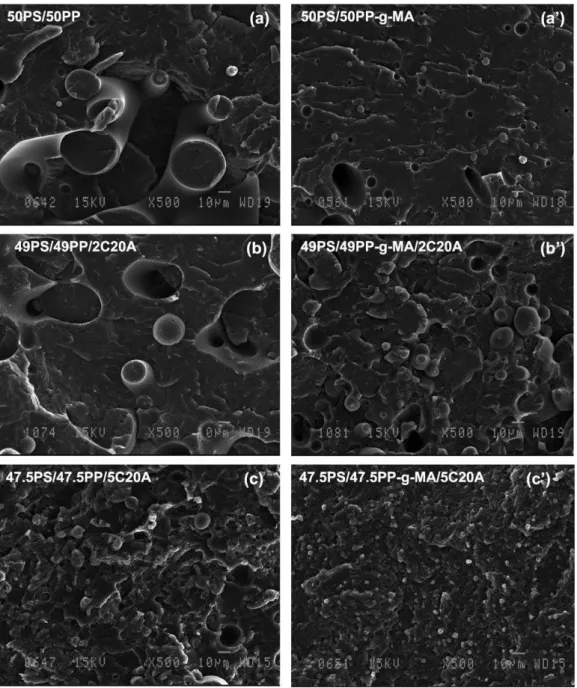
Fig. 2. SEM images of fracture surfaces of unmodified and C20A modified (50/50) PS/PP and PS/PP-g-MA blends.
Table 1
Characteristics of the polymers used in this study
Polymer Density (g/cm3) ASTM D792 Melt flow rate (g/10 min) ASTM
D1238
Supplier
PS 1.04 1.5 (200 8C/5 kg) Dow Chemicals
PP 0.902 12 (230 8C/2.16 kg) Basell-Polyolefins
PP-g-MA (MA grafting level 1. 2 wt%)
2.3. Characterization
Blend morphologies were examined by scanning elec-tron microscopy (SEM) using the JEOL model JSM-820 apparatus operating at an accelerating voltage of 15K. The samples were fractured in liquid nitrogen and then sputtered coated with gold/palladium (50/50), to avoid charging.
The actual position of intercalated and exfoliated silicate layers in blends were examined by transmission electron microscopy (TEM) using the Hitachi model H-800 apparatus operated at an accelerating voltage of 80 kV. The TEM specimens were about 50–70 nm thick. They were prepared by ultramicrotoming the blends encapsulated in epoxy at K130 8C with a diamond knife. To enhance the contrast between the phases, the sections were stained by osmium tetra-oxide, OsO4, vapor.
The XRD patterns were recorded on a Simens-500 diffractometer. The beam was Cu Ka radiation (lZ 0.154 nm) operated, at 40 kV and 40 mA. Data were obtained from 2qZ1–108 at a scanning speed of 0.12 8/min. The basal spacing of the organically modified layered silicate before and after intercalation was estimated from the position of (d001) peak in the XRD pattern.
Interfacial tension of PS/PP and PS/PP-g-MA with C20A was measured using drop deformation and relaxation technique [39]. C20A (0.5 wt%) was first mixed with PP and PP-g-MA. Thereafter a drop of PS was introduced between two films of PP or PP-g-MA. The total sandwich type assembly was put between the two parallel plates of the Linkam-shearing device mounted directly on a Zeiss optical microscope. The sample was then heated to 200 8C and sheared at this temperature at slight deformation. The shape of the drop was then recorded during the relaxation process. The interfacial tension was extracted using the technique already described elsewhere[39].
Test specimens for the tensile measurements were prepared from 1.5-mm-thick plates according to the ASTM D 638. The tensile modulus, tensile strength, and elongation at break were measured in a tensile Instron tester at the strain rate of 5 mm/min at room temperature. The data presented here are averages of eight tests with a maximum error of 9%.
3. Results and discussion
3.1. Phase morphology and XRD patterns
The typical morphologies of blends are shown inFigs. 1 and 2, where a comparison is made of SEM images taken from the fractured surfaces of unmodified and C20A modified PS/PP and PS/PP-g-MA blends. SEM images of binary (20/80) PS/PP and PS/PP-g-MA blends, given, respectively, in Fig. 1(a) and (a0), show PS particles
dispersed within the PP (PP-g-MA) matrix. It should be stressed here, that PP and PP-g-MA were two different commercial grades with different viscosities and therefore the effect of the grafted MA on particle size could not be discussed here. The only thing that can be said here is that the viscosity of PP-g-MA was lower than that of unmodified PP, which may explain the large PS particles size in
PS/PP-g-MA blend. Micrographs (b) and (b0) of Fig. 1represent
SEM images of fracture surfaces of blends with the same Table 2
Viscosity (h) of the some representative virgin and C20A modified blends at the shear rate of 50 sK1
Blends h(Pa s) 20PS/80PP 287 19PS/79PP/2C20A 77 17.5PS/77.5PP/5C20A 110 20PS/80PP-g-MA 17 19PS/79PP-g-MA/2C20A 16 17.5PS/77.5PP-g-MA/5C20A 22
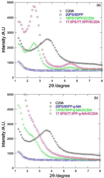
Fig. 3. XRD patterns of (a) unmodified and C20A modified (20/80) PS/PP blends and (b) unmodified and C20A modified (20/80) PS/PP-g-MA blends.
weight ratio as inFig. 1(a) and (a0), but containing 2 wt% of
C20A. The morphology of PS/PP remains quite unchanged upon addition of 2 wt% of C20A (only slight modification), with an average radius of about 8 mm, whereas a clear decrease in particles size was obtained for PS/PP-g-MA blend modified with the same amount of C20A. The addition of 5 wt% of C20A causes a further decrease in particle size. The average particle size decreased from about 8 mm in virgin PS/PP blend to about 1 mm in PS/PP modified with 5 wt% of C20A (Fig. 1(c)). In the case of PS/PP-g-MA, the decrease in particle size was more pronounced and it was not possible to distinguish the dispersed domains at this magnification (Fig. 1(c0)).
The morphology of the blends at 50/50 of PS and PP
(PP-g-MA) is shown inFig. 2. Here again, the addition of 5 wt% of C20A solid phase resulted in large modification of the state of phase dispersion and PS particle size. The 50/50 PS/ PP blend shows a somewhat interconnected morphology (Fig. 2(a)), whereas after 5 wt% of C20A addition, the state of dispersion was transformed into a dispersion-type morphology with very fine particle size and apparently good interfacial adhesion between the phases (Fig. 2(c)). A large decrease in particle size can also be observed in the case of PP-g-MA (seeFig. 2(b0) and (c0)). This observation
also indicates the possible compatibilizing effect of C20A organoclay.
Two possible effects may be evoked regarding the reduction in particle size: (i) the increase in blend’s viscosity upon addition of clay and thus high stresses are imposed to the dispersed particles and (ii) the dispersion of clay in the interfacial region that may act as a true compatibilizer. During the mixing process of the com-ponents in the batch mixer, the rotation speed was set at
60 rpm. This corresponds to an average shear rate of 50 sK1
[40]. Viscosity of the virgin and the C20A-modified blends at this shear rate is reported in Table 2. Addition of 2 and 5 wt% C20A of course increases the viscosity at low shear rate, but here only viscosity at 50 sK1corresponding to the conditions of mixing is of interest.
Clearly, the viscosity increases only very slightly in the case of PS/PP-g-MA blends with the addition of 5 wt% C20A. On the other hand, in the presence of C20A, the viscosity of PS/PP blends was low as compared to the virgin blend. This behavior may be due to the lubricating effect of C20A for PS/PP system. Therefore, the viscosity ratio cannot solely explain the dramatic decrease in particle size. To verify the eventual compatibilization effect of clay, interfacial tension of the virgin and C20A modified blends was measured using the drop deformation method [39]. Upon addition of only 0.5 wt% of C20A, the interfacial tension has decreased from 5.1 to 3.4 mN/m for PS/PP and from 4.8 to 1.1 mN/m for PS/PP-g-MA, suggesting a possible interfacial activity of C20A that may be localized at the interface in similar fashion to classical compatibilzers. To play this role, clay should be at least partially exfoliated and should have some interactions with both phases. To verify the state of dispersion of clay, X-ray diffraction analyses were carried out for the virgin C20A and C20A-modified blends.
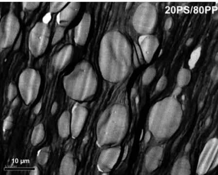
Fig. 3(a) shows the XRD patterns of pure C20A and PS/ PP (20/80) blends with 2 and 5 wt% of C20A. The intensity of the characteristic peak of C20A in 19PS/79PP/2C20A was reduced and a broad peak was observed at 2qZ2.68 (d001Z3.53 nm), indicating intercalated structure. By increasing the loading of C20A in PS/PP (20/80) blend to 5 wt%, the characteristic peak of C20A retains almost its Fig. 4. Bright field TEM image of (20/80) PS/PP blend in which white ellipsoids correspond to the dispersed PS domains.
position, but the intensity was increased sharply compared to the 2 wt% C20A containing blend. This behavior may be due to the weak interaction between the matrices and C20A, and the parallel stacking of the silicate layers increases in
the presence of high C20A content. So, with 2 or 5 wt% C20A in PS/PP (20/80) blends, silicate layers are inter-calated stacked and they prefer to stay at the interface between the two blend’s components.
The XRD patterns of pure C20A powder and PS/PP-g-MA (20/80) blends with 2 and 5 wt% C20A are shown in
Fig. 3(b). The characteristic peak of C20A was observed at 2qZ3.68 (d001Z2.48 nm). In the X-ray diffraction pattern of PS/PP-g-MA (20/80) with 2 or 5 wt% of C20A, the
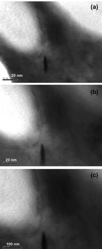
Fig. 5. Bright field TEM images of 17.5PS/77.5PP/5C20A blend.
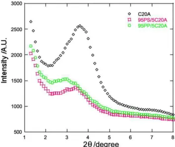
Fig. 6. XRD patterns of PS/5C20A and PP/5C20A hybrids.
Table 3
Tensile properties of pure polymers and corresponding blends with or without C20A
Sample Modulus (MPa) Strength (MPa) Elongation at break (mm) PS 1476G80.7 35.5G2.6 0.7G0.06 PP 682.5G94.8 27.3G2.1 3G1.4 PP-g-MA 1023G81.1 13.6G3.1 0.4G0.1 20PS/80PP 836.6G43.2 15.5G1.7 1.5G0.2 19PS/79PP/ 2C20A 914.4G43.6 6G0.06 6.2G0.8 17.5PS/77.5PP/ 5C20A 952.1G0.1 5G0.1 4.4G1.2 50PS/50PP 1169.1G51.2 13.5G3.1 0.3G0.07 49PS/49PP/ 2C20A 1239.5G112 12.3G1 0.26G0.02 47.5PS/47.5PP/ 5C20A 1322G91 12.1G1.1 0.23G0.03 20PS/80PP-g-MA 1299G102 5.2G0.4 0.6G0.06 19PS/79PP-g-MA/2C20A 1536.4G170 5G1 0.11G0.03 17.5PS/77.5PP-g-MA/5C20A 2503G212 4.1G0.4 0.08G0.02 50PS/50PP-g-MA 1276G134 8.8G1.4 0.2G0.04 49PS/49PP-g-MA/2C20A 1363G150 7G1 0.12G0.03 47.5PS/47.5PP-g-MA/5C20A 1797G118 7.4G1.3 0.13G0.04
characteristic peak of C20A disappears, indicating that the structure is potentially highly intercalated and exfoliated (in the case of 5% of C20A), due to the presence of the polar MA grafted group on the PP backbone.
To have more insight into C20A interfacial activity, local TEM analyses were carried out to localize the clay particles
in the blend.Fig. 4 is a bright field TEM image of PS/PP (20/80) blend that gives a general view of the dispersed PS domains (white ellipsoid) in the PP matrix. It also gives the size of PS domains, which is in good agreement with the average diameter determined for SEM images (Fig. 1(a)).
Fig. 5 shows the interfacial region in PS/PP blend with a weight ratio of 20/80 modified with 5 wt% of C20A addition. The micrographs reveal that the intercalated silicate layers are located at the interface between the blend components. The possible explanation of this observation is that both PS and PP have no strong interaction with C20A, but both were intercalated into the C20A silicate layers as was noticed on the XRD patterns in
Figs. 3(a) and 6. In the XRD pattern (Fig. 6) of the PS/C20A blend with 5 wt% of C20A, the characteristic peak of C20A appears at 2qZ3.38 (2.67 nm), indicating poorly interca-lated structure. PP/C20A blend with the same wt% of C20A has an interlayer distance of 2.95 nm (2qZ38). Interest-ingly, when 20PS/80PP blend is mixed with 5 wt% of C20A, the interlayer distance of C20A is further increased to 3.53 nm (2qZ2.68). This observation suggests that both PS and PP chains are intercalated into the C20A silicate layers. Therefore, the intercalated silicate layers are pushed towards the interphase due to the common intercalation. This results in a situation, where the layered silicates are shared by the two polymers and therefore C20A acts as an interfacial compatibilizer. This leads to a reduction in interfacial tension and thus to a reduction in PS domains size.
At the other extreme, TEM images (seeFig. 7) of
PS/PP-g-MA (20/80) blend modified with 5 wt% of C20A addition depict that the C20A particles are mainly dispersed in the PP-g-MA matrix. The relative position of the C20A particles and the PS domains is better seen in high magnification images in Fig. 7(b) and (c), respectively, where most of the exfoliated silicate layers (as noticed on XRD patterns in Fig. 3(b)) are dispersed in the PP-g-MA matrix and surround the PS domains.
These observations offer a possible explanation for the compatibilization effect of C20A. The exfoliated silicate layers disperse around the PS phase, inhibiting the coalescence of the PS domains. This effect becomes more important as the C20A loading increases. For blends with 2 wt% of C20A, some domains of the dispersed PS are observed but with 5 wt% of C20A, the dispersed domains were not observable at the studied magnification.
Now if one assumes that clay particles are fully exfoliated and all clay platelets are located at the surface of the PS particles, then the volume fraction of clay (fc)
needed to saturate the PS particles surface is given by: fcZ3e
R fPS (2)
where e is the thickness of clay platelets, R is the PS average droplet radius, and fPS is the volume fraction of PS. The
above equation was derived by assuming that all clay Fig. 7. Bright field TEM images of 17.5PS/77.5PP-g-MA/5C20A blend.
particles are located at the surface of PS drops supposed spherical with average radius R. The above equation shows that for PS volume fraction of 20 wt%, fc is of about
0.001% (RZ8 mm and ew1 nm). This simple argument shows that the saturation concentration is very small when clay is fully exfoliated. This supports the emulsification hypothesis of the clay particles. Additionally, for the concentrations selected in this work (0.02 and 0.05), one expects clay to play a double role: (i) compatibilizing agent and (ii) reinforcing filler. This means that one expects clay particles to be located both at the interface as well as in the bulk region.
In the case of 19PS/79PP-g-MA/2C20A blend, the size of
PS droplets sharply decreased in comparison with 20PS/80PP-g-MA blend, but apparently clay was not fully compatible with PP-g-MA matrix although the added clay volume fraction (0.02) was much higher than the calculated one. This observation indicates that clay particles were not in a fully exfoliated state and need more clay platelets to cover the remaining PS droplets. For this reason, when the added clay was 5 wt% (0.05 volume fraction), the dispersed particles were not observable at this magnification.
3.2. Mechanical properties
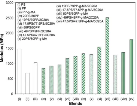
To further confirm the effect of compatibilization of Fig. 8. Tensile modulus of pure polymers and corresponding blends with or without C20A.
C20A in PS/PP blends, mechanical properties of virgin and clay-modified blends were studied in traction mode. The results are reported inTable 3. For visualization purposes, the results are also reported in Figs. 8–10 for the tensile modulus, strength, and elongation at break, respectively, without the error bars.Table 3andFig. 8show that PS has a modulus that is almost twice that of PP and PP-g-MA has a modulus that lies between those of PS and PP. The moduli of blends without C20A are quite arithmetic mean values of those of the pure components. Addition of C20A increases the modulus with respect to the virgin blend, but the modulus remains lower than that of the pure PS. Spectacular increase in modulus is obtained upon 5 wt% of C20A addition to PS/PP-g-MA (20/80). This is consistent with the micrograph (c0) of Fig. 1 that shows high level of
compatibilization due to the peculiar interactions between MA and C20A, and the insertion of PS chains into the clay galleries (intercalation).
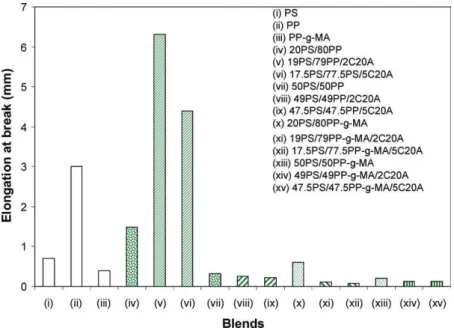
The tensile strength of all unmodified PS/PP or PP-g-MA blends decreases with PS content (Fig. 9). This is obvious because PP is a ductile polymer and the incorporation of second rigid polymer in the PP matrix often results in a decreased strength and elongation at break (Fig. 10). The tensile strength of all blends decreases with the addition of C20A. Such a decrease is more important when C20A concentration increases. This indicates that the PP matrix primarily controls the tensile strength. Curiously, addition of 2 and 5 wt% of C20A increases drastically the elongation at break of the PS/PP (20/80) blend (Fig. 10). Clearly, in these two cases, C20A plays not only the role of the filler but also that of an interfacial active agent that promotes adhesion between the phases.
In the previous section we have suggested that C20A could be a better compatibilizer for PS/PP-g-MA blends
than for PS/PP blends. The values of tensile modulus and strength (Figs. 8 and 9) of PS/PP-g-MA blends with both 2 and 5 wt% of C20A addition are much higher than those of their corresponding PS/PP blends. These data fully confirm the role of C20A as a true compatibilizer as was previously assessed by SEM and TEM observations and by the reduction in interfacial tension and average particle size.
4. Concluding remarks
The presence of C20A in the PS/PP or PS/PP-g-MA blends was studied by various techniques including XRD, SEM, TEM, interfacial tension measurements, and mech-anical tests in the traction mode. The results clearly indicate that C20A acts at the same time as a nanofiller and also as a compatibilizer. TEM analyses showed that CA20A is located at the interface. Such interfacial activity resulted in dramatic decrease in interfacial tension and thus in particle size for both PS/PP and PS/PP-g-MA blends. The compatibilization process was more efficient when PP is grafted with maleic anhydride that ensures interactions with clay side OH groups. Such a result was also confirmed by mechanical properties that show a high increase in modulus for 17.5PS/77.5PP-g-MA/5C20A.
Acknowledgements
The natural Sciences and Engineering Research Council of Canada (NSERC) and the Canada Research Chair on Polymer Physics and Nanomaterials financially supported this work.
References
[1] Ajji A. In: Utracki LA, editor. Polymer blends handbook. Dordrecht: Kluwer Academic; 2002 [chapter 4].
[2] Brown SB. In: Utracki LA, editor. Polymer blends handbook. Dordrecht: Kluwer Academic; 2002 [chapter 5].
[3] Machado JM, Lee CS. Polym Eng Sci 1994;34:59–68.
[4] Kwei TK, Frisch HC, Radigan W, Vogel S. Macromolecules 1977;10: 157–60.
[5] Locke CE, Paul DR. J Appl Polym Sci 1973;17:2597–617. [6] Barentsen WM, Heikens D, Piet P. Polymer 1974;15:119–22. [7] Fayt R, Jerome R, Teyssie Ph. J Polym Sci Part B: Polym Phys 1981;
19:1269–72.
[8] Schwarz MC, Barlow JW, Paul DR. J Appl Polym Sci 1988;35: 2053–67.
[9] Hlavata D, Horak Z, Hromadkova J, Lednicky F, Pleska A. J Polym Sci Part B: Polym Phys 1999;37:1647–56.
[10] Hlavata D, Horak Z, Lednicky F, Hromadkova J, Pleska A, Zanevskii YV. J Polym Sci Part B: Polym Phys 2001;39:931–42. [11] Radonjic G, Musil V, Smit I. J Appl Polym Sci 1998;69:2625–39. [12] Baker WE, Saleem WE. Polym Eng Sci 1987;27:1634–41. [13] Utracki LA, editor. Encyclopaedic dictionary of commercial polymer
blends. Toronto, Canada: ChemTec Publishing; 1994.
[14] Lipatov YS. Polymer reinforcement. Toronto, Canada: ChemTec Publishing; 1995.
[15] Fleer G, Cohen-Stuart MA, Scheutjens JMHM, Cosgrove T, Vincent B. Polymers at interfaces. London: Chapman & Hall; 1993. [16] Cosgrove T, Heath TG, Phipps JS, Richardson RM. Macromolecules
1991;24:94–8.
[17] Klein J, Kamiyama Y, Yoshizawa H, Israelachvili JN, Fredrickson GN, Pincus P, Fetters LJ. Macromolecules 1993;26: 5552–60.
[18] Utracki LA. Clay-containing polymeric nanocomposites. Shawbury, Shewsbury UK: RAPRA; 2004.
[19] Fukui O, Tsutsui K, Akagawa T, Sakai I, Nomura T, Nishio T, Yokoi T, Kawamura N. Thermoplastic resin composition. US Pat., 5,091,462, 25.02.1992, to Ube Industries Ltd.
[20] Chen TK, Tien YI, Wei KH. J Polym Sci Part A: Polym Chem 1999; 37:2225–33.
[21] Tabtiang A, Lumlong S, Venables RA. Polym Plast Technol Eng 2000;39:293–303.
[22] Hasegawa N, Okamoto H, Kawasumi M, Usuki A, Okada A. Resin composite. US Pat., 6,117,932, 2000.09.12, Appl. 1998.09.17, to Kabushiki Kaisha Toyota Chuo Kenkyusho.
[23] Zhu SM, Liu Y, Rafailovich M, Sokolov J, Gersappe D, Winesett DA, Ade H. Abstr Pap ACS 1999;218:109.
[24] Ferreiro V, Douglas JF, Amis EJ, Karim A. Macromol Symp 2001; 167:73–88.
[25] Wang H, Zeng CC, Elkovitch M, Lee JL, Koelling KW. Polym Eng Sci 2001;41:2036–46.
[26] Voulgaris D, Petridis D. Polymer 2002;43:2213–8.
[27] Gelfer MY, Song HH, Liu L, Hsiao BS, Chu B, Rafailovich M, Si M, Zaitsev V. J Polym Sci Part B: Polym Phys 2003;41:44–54. [28] Wang Y, Zhang Q, Fu Q. Macromol Rapid Commun 2003;24:231–5. [29] Yurekli K, Karim A, Amis EJ, Krishnamoorti R. Macromolecules
2003;36:7256–67.
[30] Yurekli K, Karim A, Amis EJ, Krishnamoorti R. Macromolecules 2004;37:507–15.
[31] Wang S, Hu Y, Song L, Liu J, Chen Z, Fan WJ. Appl Polym Sci 2004; 91:1457–62.
[32] Kawasumi M, Hasegawa N, Kato M, Usuki A, Okada A. Macromol-ecules 1997;30:6333–8.
[33] Hasegawa N, Okamoto H, Kato M, Usuki A. J Appl Polym Sci 2000; 78:1918–22.
[34] Galgali G, Ramesh C, Lele A. Macromolecules 2001;34:852–8. [35] Manias E, Touny A, Wu L, Strawhecker K, Lu B, Chung TC. Chem
Mater 2001;13:3516–23.
[36] Grim RE. Clay mineralogy. New York: McGraw-Hill; 1953. [37] Sinha Ray S, Okamoto M. Prog Polym Sci 2003;28:1539–641. [38] Southern Clay Products, Texas, data sheet.
[39] Xing P, Bousmina M, Rodrigue D, Kamal MR. Macromolecules 2000;33:8020–34.