Publisher’s version / Version de l'éditeur:
Questions? Contact the NRC Publications Archive team at
[email protected]. If you wish to email the authors directly, please see the first page of the publication for their contact information.
https://publications-cnrc.canada.ca/fra/droits
L’accès à ce site Web et l’utilisation de son contenu sont assujettis aux conditions présentées dans le site LISEZ CES CONDITIONS ATTENTIVEMENT AVANT D’UTILISER CE SITE WEB.
8th Canadian Marine Hydromechanics and Structures Conference [Proceedings],
2007
READ THESE TERMS AND CONDITIONS CAREFULLY BEFORE USING THIS WEBSITE.
https://nrc-publications.canada.ca/eng/copyright
NRC Publications Archive Record / Notice des Archives des publications du CNRC :
https://nrc-publications.canada.ca/eng/view/object/?id=a747c7f1-21de-4ffc-bcfd-cb2942fa2bfe
https://publications-cnrc.canada.ca/fra/voir/objet/?id=a747c7f1-21de-4ffc-bcfd-cb2942fa2bfe
NRC Publications Archive
Archives des publications du CNRC
This publication could be one of several versions: author’s original, accepted manuscript or the publisher’s version. / La version de cette publication peut être l’une des suivantes : la version prépublication de l’auteur, la version acceptée du manuscrit ou la version de l’éditeur.
Access and use of this website and the material on it are subject to the Terms and Conditions set forth at
Mapping motion responses for the Newfoundland fishing fleet
Mapping Motion Responses for the Newfoundland Fishing
Fleet
Akinturk A
1, Cumming D
1and Bass D
21Institute for Ocean Technology, National Research Council Canada
St. John’s, NL, A1B 3T5, Canada
2Faculty of Engineering and Applied Science, Memorial University of Newfoundland
St. John’s, NL, A1B 3X5, Canada
Email: [email protected]
A
BSTRACTIn a recent study to evaluate the occupational risks induced by ship motions on the fishing fleet of Newfoundland under the umbrella of the community initiative called SafetyNet, five fishing vessels of various sizes were evaluated during sea trials carried outapproximately 10 nautical miles off St. John’s – Newfoundland. The selection of the sizes was intended to be representative of the whole fleet – 35’, 45’, two 65’ and 75’. The two 65’ vessels had motion reducing devices: one paravanes and the other anti-roll tanks - both commonly used in this fleet. This paper describes the vessels and the trials’ conditions. The measured motions responses for roll, pitch and yaw, accelerations for surge, sway and heave are given in the paper.
1. I
NTRODUCTIONThis study reports the findings of the sea trials of the five fishing vessels conducted under the Fishing Vessel Safety Project, which is a small component of the overall SafetyNet [1] initiative to understand and mitigate the health and safety risks associated with employment in a marine environment. SafetyNet is the first federally funded research program investigating occupational health and safety in historically high risk Atlantic Canada marine, coastal and offshore industries. As part of the SafetyNet initiative, the Fishing Vessel Safety Project conducted research on the occupational health and safety of seafood harvesters. Fishing is the most dangerous occupation in Newfoundland and Labrador and is increasingly so: over the past ten years, the rates of reported injuries and fatalities nearly doubled. These trends have the effects of reducing the sustainability of the fishery, increasing health care and compensation costs, and straining the
available search and rescue (SAR) resources. The development of effective solutions, to prevent or mitigate injury, fatality or SAR events, has been seriously hindered by the scarcity of the research needed to understand the factors that influence seafood harvester occupational health and safety. The Fishing Vessel Safety project is a multi-disciplinary, inter-departmental and inter-sectorial research project. The broad-based and multi-factorial approach in investigating the inter-related factors that influence fishing safety including: fishery policy and vessel regulations, vessel safety design and modeling, human relationships on vessels and health and safety program development, implementation and evaluation.
The goal of the study reported in this paper was to obtain benchmark test cases to verify and validate the numerical tool being developed, namely MOTSIM ([2] and [3]). This tool has been used to extend the information developed on the motion profiles of the fishing fleet of Newfoundland. This information has then been used to model the effects of Motion Induced Interruptions (MII) for these vessels hence, to develop criteria to reduce MIIs ([4], [5], [6] and [7]).
The five fishing vessels used in this study varied in size from 10.64m to 22.86m (35’ to 75’), with the two of them having motion reducing devices in the form of paravanes and anti-roll tanks. A detailed description of the vessels and the trials procedure are given in [8]. This paper presents the motion responses of these vessels measured during the sea trials together with the descriptions of the sea conditions.
2. D
ESCRIPTION OF THEF
ISHINGV
ESSELSThe five fishing vessels used in the trials are designated as FV_A, FV_B, FV_C1, FV_C2 and FV_D. Their principal particulars are given in Table 1.
FV_A is a typical 35’ fiberglass fishing vessel, which primarily participates in the inshore snow crab fishery, but has the ability to harvest other species, such as codfish and capelin, when the stocks are available. It has a round bilge, single screw (fixed pitch, 4 blade propeller), single flat plate rudder vessel with a large centerline skeg and no dedicated anti-roll device other than a set of rolling chocks. The second fishing vessel, FV_B is a typical 45’ (13.69 m) fiberglass fishing vessel operated in Newfoundland waters. The vessel primarily participates in the inshore snow crab fishery, but has the ability to harvest other species using a gillnetting setup, such as codfish and capelin, when the stocks are available. It has no dedicated anti-roll device. FV_C1 is a 65’ (19.79 m) fiberglass fishing vessel. The vessel primarily participates in the inshore snow crab fishery, but has the ability to harvest other species using a trawl, such as shrimp and ground fish, when the stocks are available. The vessel has an anti-roll tank installed on board to reduce anti-roll motion. Another 65’ fishing vessel used in the trials was FV_C2. Unlike FV_C1, this is a steel vessel and uses paravanes to reduce roll motion. The vessel primarily participates in the inshore snow crab and shrimp fisheries, but has the ability to harvest other species, such as codfish, turbot, and capelin when the stocks are available.
FV_D is a 75’ long inshore fisheries research vessel and generally used by scientists to carry out fisheries related research around coastal Newfoundland. Table 1 Principal particulars of the vessels
Particulars FV_A FV_B FV_C1 FV_C2 FV_D LOA, (m) 10.64 13.69 19.79 19.80 24.9 B, (m) 4.27 7.01 7.01 7.32 6.7 D, (m) 1.52 3.05 3.81 3.05 3.5 , (tons) 16.87 78.24 228.5 251 201.4 MaxSpeed, (knots) 8 8 9 9 8
Damping? No No Yes Yes No
Notes: FV_C1 has anti roll tanks installed FV_C2 has paravanes
3. D
ESCRIPTION OF THEW
AVEC
ONDITIONSD
URING THET
RIALSDuring the trials, the target wave conditions were such that the vessel should be safe to operate (able to fish) but induce significant motions.
Table 2 gives the natural roll and pitch periodsof the vessels used in the trials. It shows that these vessels would be excited by rather high frequency waves at sea.
Table 2 Natural roll and pitch periods of the vessels Fishing Vessel Roll Period (s) Pitch Period (s)
FV_A 3.22 2.57
FV_B 3.89 3.62
FV_C1 6.34 4.01
FV_C2 7.94 4.65
FV_D 6.07 3.94
Variations for the representative wave parameters, i.e. Significant Wave Height (SWH) and Dominant Wave Period, (DWP), for the trials are given in the Figures 1 to 5. Each figure shows the variations in the waves approximately for the period of each trial. For Figure 1, wave parameters after the10 hour mark are predicted as the wave buoy broke down during the trials. Although the dominant wave period remained around the 7.5 s mark, the significant wave height showed a decreasing trend throughout the day. The higher energy was contained in relatively larger waves during the trials of FV_A.
During the trials of FV_B, the waves maintained a 1.75 m to 2 m significant wave height and the energy again contained in the larger waves for this vessel (Figure 2).
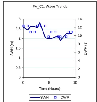
The target significant wave heights for the trials of the two 65’ vessels, FV_C1 and FV_C2 were 2.5 m to 3 m. For FV_C1, the trials began at the desired significant wave height level, however, it dropped as the trials progressed. Similar conditions were also observed for FV_C2. Completion of the trials for FV_C2 was spread over two different days. As Figure 4 shows, the second day had even smaller waves.
Figure 5 presents the variations in waves for the sea trials of the longest vessel used in this study. Significant wave height was lower than the desired level and the highest energy waves had longer periods than its roll and pitch natural frequencies.
3
FV_A: Wave Trends
0 0.5 1 1.5 2 2.5 3 0 5 10 15 Time (Hours) S W H ( m ) 0 1 2 3 4 5 6 7 8 9 D W P ( s ) SWH DWP
Figure 1 Wave properties during the sea trials for FV_A FV_B: Wave Trends 0 0.5 1 1.5 2 2.5 0 2 4 6 Time (Hours) S W H ( m ) 0 2 4 6 8 10 12 D W P ( s ) SWH DWP
Figure 2 Wave properties during the sea trials for FV_B FV_C1: Wave Trends 0 0.5 1 1.5 2 2.5 3 0 5 10 Time (Hours) S W H ( m ) 0 2 4 6 8 10 12 14 D W P ( s ) SWH DWP
Figure 3 Wave properties during the sea trials for FV_C1 FV_C2: Wave Trends 0 0.5 1 1.5 2 2.5 3 0 5 10 Time (Hours) S W H ( m ) 0 2 4 6 8 10 12 14 D W P ( s ) SWH, Day 1 SWH, Day 2 DWP, Day 1 DWP, Day 2
Figure 4 Wave properties during the sea trials for FV_C2
FV_D: Wave Trends 0 0.5 1 1.5 2 2.5 0 2 4 6 Time (Hours) S W H ( m ) 0 2 4 6 8 10 12 14 16 18 D W P ( s ) SWH DWP
Figure 5 Wave properties during the sea trials for FV_D
4. R
ESULTS ANDD
ISCUSSIONSSeakeeping trials were performed at two different vessel speeds: trawling (3 – 4 knots) and cruising (~8 knots). If the vessel had dedicated anti-roll devices, the trials were repeated with and without those devices operational. Motion responses obtained during the trials are given at the end of this paper in Figures 7 to 11 as standard deviations.
One of the problems encountered during the trials was in determining the dominant wave direction. Natural frequencies based on Table 2 vary between 0.15 to 0.33 Hz approximately. A sample spectrum and the wave spread taken from the seakeeping trials are given in Figure 6. A careful examination of the wave spread (solid squares in the figure) reveal that there is almost a 180 degree spread of wave directions in the frequency range of interest, i.e. 0.125 to 0.33 Hz. It is almost like a large swell coming from one direction and wind generated smaller waves approaching from the opposite. Similar situations were noted throughout the seakeeping trials of these vessels. Therefore, heading angle in the figures (Figures 7 to 11) should be treated with a caution. For example, Figure 7 (a) and (b) show the roll and pitch amplitudes versus headings. Intuitively, one would expect the higher pitch motions occur in head seas than in beam seas. Similarly, the highest roll can be expected in beam seas. The following points should be considered when interpreting the results presented in Figures 7 to 11:
Nondirectional Spectrum - Oct. 17, 2004 @1100 0 2 4 6 8 0.0 0.2 0.4 0.6 Frequency (Hz) C 1 1 ( m 2 /H z ) 0 100 200 300 400 D e g re e s
Spectrum Wave Direction
Figure 6 Sample spectrum and the wave spread taken from one of the sea trials data
• Heading designation should be taken with caution. Waves were continually changing both in magnitude and direction. Therefore, the direction for head seas in the morning may not be the same in the afternoon of the day of a trial.
• The results presented include effects due to the changing of wave amplitudes. Hence, some of the variations in motion responses from one heading to another include this kind of effect.
• FV_A did not have an autopilot. The helmsman seemed to be avoiding the large wave encounters therefore following rather a zigzag course than a straight one. This in turn affected the motion responses.
With respect to anti-roll devices, both anti-roll tanks and paravanes seemed to work fine (figures 9 and 10) perhaps with some penalties in other motions. As mentioned above, these penalties may be due to some other effects.
5. CONCLUSIONS
Seakeeping trials of five fishing vessels were completed successfully and some of the motion responses are reported in this paper.
What stands out in the polar plots is the comparatively small changes that occur in most motions as heading changes. The changes that do
5 occur (e.g. roll angle for FV_A in Figure 7 (a)) may be more related to wave changes.
Anti-roll devices used in these trials, anti-roll tanks and paravanes effectively reduced the roll motion amplitudes. However, they seem to introduce some small penalties in other motions. This remains to be studied further.
A
CKNOWLEDGEMENTSThe authors would like to thank all the crews of the participating fishing vessels for their enthusiastic and professional support during the sea trials, Mr. Jack Foley, MUN Dept. of Physics and Physical Oceanography and Mr. Reg Fitzgerald of Oceans Ltd. for their wave buoy support, the crew of the M.V Louis M. Lauzier for their assistance in deploying/recovering the Datawell wave buoy, Oceanic Consulting Corp. for transport support, the Canadian Coast Guard for the loan of life saving equipment, the Offshore Survival & Safety Center for IOT staff Marine Emergency Duty training and IOT technical staff for their efforts throughout the planning and execution of the sea trial. Funding support from the Search & Rescue New Initiatives Fund (SAR/NIF) and the Canadian Institutes of Health and Research (CIHR) is gratefully acknowledged. Last but not least, the staff members of IOT who contributed a lot to the success of these trials deserve heart felt thanks.
N
OMENCLATUREART Anti-Roll Tank
DWP Dominant Wave Period (s) Fr Froude number
MII Motion Induced Interrupts SAR Search And Rescue
SWH Significant Wave Height (m)
R
EFERENCES[1] “SafetyNet – a Community Research Alliance on Health and Safety in Marine and Coastal Work”, www.SafetyNet.MUN.ca, September 2003.
[2] Pawlowski, J.S. and D.W. Bass, ”A Theoretical and Numerical Study of Ship Motions in Heavy Seas”, SNAME Trans., Vol. 99, 1991, pp. 319-352.
[3] Bass, D., Vera, J., Cumming, D. and Akinturk, A. “Developing a Numerical Tool to Predict Crew Safety Related Parameters for Fishing Vessels” Proceeding of the Canadian Marine Hydromechanics and Structures Conference, Halifax, Nova Scotia, 2005.
[4] Stevens, S.C., Parsons, M.G., “Effects of Motion at Sea on Crew Performance: A Survey”, SNAME Publication Marine Technology, Vol. 39, No. 1, January 2002, pp. 29 – 47.
[5] Boccadamo, G., Cassella, P., Scamardella, A., “Stability, Operability and Working Conditions Onboard Fishing Vessels”, 7th International Conference on Stability of Ships and Ocean Vehicles, Launceston, Tasmania, Australia, February 7-11, 2000.
[6]
Crossland, P., Rich, K.J.N.C., “A Method for Deriving MII Criteria”, Conference on Human Factors in Ship Design and Operation, London, UK, September 27 – 29, 2000.[7] Graham, R., “Motion-Induced Interruptions as Ship Operability Criteria”, Naval Engineers Journal, March 1990.
[8]
Cumming, D. and Fleming, T. “Practical Considerations Related to Carrying Out Seakeeping Trials on Small Fishing Vessels” Proceeding of the Canadian Marine Hydromechanics and Structures Conference, Halifax, Nova Scotia, 2005.2 2 2 2 4 4 4 4 6 6 6 6 30 210 60 240 90 270 120 300 150 330 180 0 Heading (degrees) Fr = 0.2 Fr = 0.4 (de gre e s ) (de gre e s ) (de gre e s ) (de gre e s ) 1 1 1 1 2 2 2 2 3 3 3 3 30 210 60 240 90 270 120 300 150 330 180 0 Heading (degrees) Fr = 0.2 Fr = 0.4 (de gre e s ) (de gre e s ) (de gre e s ) (de gre e s ) 5 5 5 5 1 0 1 0 1 0 1 0 1 5 1 5 1 5 1 5 2 0 2 0 2 0 2 0 2 5 2 5 2 5 2 5 30 210 60 240 90 270 120 300 150 330 180 0 Heading (degrees) Fr = 0.2 Fr = 0.4 (de gre e s ) (de gre e s )(de gre e s ) (de gre e s )
(a) Roll angle (b) Pitch angle (c) Yaw angle
0 .1 0 .1 0 .1 0 .1 0 .2 0 .2 0 .2 0 .2 0 .3 0 .3 0 .3 0 .3 0 .4 0 .4 0 .4 0 .4 0 .5 0 .5 0 .5 0 .5 30 210 60 240 90 270 120 300 150 330 180 0 Heading (degrees) Fr = 0.2 Fr = 0.4 (m ) (m ) (m ) (m ) 0 .1 0 .1 0 .1 0 .1 0 .2 0 .2 0 .2 0 .2 0 .3 0 .3 0 .3 0 .3 0 .4 0 .4 0 .4 0 .4 30 210 60 240 90 270 120 300 150 330 180 0 Heading (degrees) Fr = 0.2 Fr = 0.4 (m ) (m ) (m ) (m ) 0 .1 0 .1 0 .1 0 .1 0 .2 0 .2 0 .2 0 .2 0 .3 0 .3 0 .3 0 .3 0 .4 0 .4 0 .4 0 .4 0 .5 0 .5 0 .5 0 .5 30 210 60 240 90 270 120 300 150 330 180 0 Heading (degrees) Fr = 0.2 Fr = 0.4 (m ) (m )(m ) (m )
(d) Surge displacement (e) Sway displacement (f) Heave displacement
0 .1 0 .1 0 .1 0 .1 0 .2 0 .2 0 .2 0 .2 0 .3 0 .3 0 .3 0 .3 0 .4 0 .4 0 .4 0 .4 30 210 60 240 90 270 120 300 150 330 180 0 Heading (degrees) Fr = 0.2 Fr = 0.4 (m /s (m /s (m /s (m /s2222)))) 0 .1 0 .1 0 .1 0 .1 0 .2 0 .2 0 .2 0 .2 0 .3 0 .3 0 .3 0 .3 0 .4 0 .4 0 .4 0 .4 30 210 60 240 90 270 120 300 150 330 180 0 Heading (degrees) Fr = 0.2 Fr = 0.4 (m /s (m /s(m /s (m /s2222 )))) 0 .2 0 .2 0 .2 0 .2 0 .4 0 .4 0 .4 0 .4 0 .6 0 .6 0 .6 0 .6 0 .8 0 .8 0 .8 0 .8 1 1 1 1 30 210 60 240 90 270 120 300 150 330 180 0 Heading (degrees) Fr = 0.2 Fr = 0.4 (m /s (m /s(m /s (m /s2222 ))))
(g) Surge acceleration (h) Sway acceleration (i) Heave acceleration
Figure 7 Motion responses for different headings for FV_A. Motion responses are given as standard deviations. (0° - following seas, 90° - beam seas and 180° head seas)
7 2 2 2 2 4 4 4 4 6 6 6 6 30 210 60 240 90 270 120 300 150 330 180 0 Heading (degrees) Fr = 0.18 Fr = 0.35 (de gre e s ) (de gre e s ) (de gre e s ) (de gre e s ) 1 1 1 1 2 2 2 2 3 3 3 3 4 4 4 4 30 210 60 240 90 270 120 300 150 330 180 0 Heading (degrees) Fr = 0.18 Fr = 0.35 (de gre e s ) (de gre e s )(de gre e s ) (de gre e s ) 1 1 1 1 2 2 2 2 3 3 3 3 4 4 4 4 30 210 60 240 90 270 120 300 150 330 180 0 Heading (degrees) Fr = 0.18 Fr = 0.35 (de gre e s ) (de gre e s ) (de gre e s ) (de gre e s )
(a) Roll angle (b) Pitch angle (c) Yaw angle
0 .2 0 .2 0 .2 0 .2 0 .4 0 .4 0 .4 0 .4 0 .6 0 .6 0 .6 0 .6 30 210 60 240 90 270 120 300 150 330 180 0 Heading (degrees) Fr = 0.18 Fr = 0.35 (m ) (m )(m ) (m ) 0 .1 0 .1 0 .1 0 .1 0 .2 0 .2 0 .2 0 .2 0 .3 0 .3 0 .3 0 .3 0 .4 0 .4 0 .4 0 .4 30 210 60 240 90 270 120 300 150 330 180 0 Heading (degrees) Fr = 0.18 Fr = 0.35 (m ) (m ) (m ) (m ) 0 .2 0 .2 0 .2 0 .2 0 .4 0 .4 0 .4 0 .4 0 .6 0 .6 0 .6 0 .6 30 210 60 240 90 270 120 300 150 330 180 0 Heading (degrees) Fr = 0.18 Fr = 0.35 (m ) (m ) (m ) (m )
(d) Surge displacement (e) Sway displacement (f) Heave displacement
0 .1 0 .1 0 .1 0 .1 0 .2 0 .2 0 .2 0 .2 0 .3 0 .3 0 .3 0 .3 0 .4 0 .4 0 .4 0 .4 30 210 60 240 90 270 120 300 150 330 180 0 Heading (degrees) Fr = 0.18 Fr = 0.35 (m /s (m /s(m /s (m /s2222)))) 0 .1 0 .1 0 .1 0 .1 0 .2 0 .2 0 .2 0 .2 0 .3 0 .3 0 .3 0 .3 0 .4 0 .4 0 .4 0 .4 30 210 60 240 90 270 120 300 150 330 180 0 Heading (degrees) Fr = 0.18 Fr = 0.35 (m /s (m /s (m /s (m /s2222)))) 0 .5 0 .5 0 .5 0 .5 1 1 1 1 1 .5 1 .5 1 .5 1 .5 30 210 60 240 90 270 120 300 150 330 180 0 Heading (degrees) Fr = 0.18 Fr = 0.35 (m /s (m /s (m /s (m /s2222))))
(g) Surge acceleration (h) Sway acceleration (i) Heave acceleration
Figure 8 Motion responses for different headings for FV_B. Motion responses are given as standard deviations. (0° - following seas, 90° - beam seas and 180° head seas)
1 1 1 1 2 2 2 2 3 3 3 3 4 4 4 4 5 5 5 5 30 210 60 240 90 270 120 300 150 330 180 0 Heading (degrees) No damping Fr = 0.15 No damping Fr = 0.30 ART Fr = 0.15 (de gre e s ) (de gre e s )(de gre e s ) (de gre e s ) 0 .5 0 .5 0 .5 0 .5 1 1 1 1 1 .5 1 .5 1 .5 1 .5 2 2 2 2 2 .5 2 .5 2 .5 2 .5 30 210 60 240 90 270 120 300 150 330 180 0 Heading (degrees) No damping Fr = 0.15 No damping Fr = 0.30 ART Fr = 0.15 (de gre e s ) (de gre e s ) (de gre e s ) (de gre e s ) 1 1 1 1 2 2 2 2 3 3 3 3 30 210 60 240 90 270 120 300 150 330 180 0 Heading (degrees) No damping Fr = 0.15 No damping Fr = 0.30 ART Fr = 0.15 (de gre e s ) (de gre e s )(de gre e s ) (de gre e s )
(a) Roll angle (b) Pitch angle (c) Yaw angle
0 .2 0 .2 0 .2 0 .2 0 .4 0 .4 0 .4 0 .4 0 .6 0 .6 0 .6 0 .6 30 210 60 240 90 270 120 300 150 330 180 0 Heading (degrees) No damping Fr = 0.15 No damping Fr = 0.30 ART Fr = 0.15 (m ) (m ) (m ) (m ) 0 .1 0 .1 0 .1 0 .1 0 .2 0 .2 0 .2 0 .2 0 .3 0 .3 0 .3 0 .3 0 .4 0 .4 0 .4 0 .4 0 .5 0 .5 0 .5 0 .5 30 210 60 240 90 270 120 300 150 330 180 0 Heading (degrees) No damping Fr = 0.15 No damping Fr = 0.30 ART Fr = 0.15 (m ) (m ) (m ) (m ) 0 .2 0 .2 0 .2 0 .2 0 .4 0 .4 0 .4 0 .4 0 .6 0 .6 0 .6 0 .6 30 210 60 240 90 270 120 300 150 330 180 0 Heading (degrees) No damping Fr = 0.15 No damping Fr = 0.30 ART Fr = 0.15 (m ) (m ) (m ) (m )
(d) Surge displacement (e) Sway displacement (f) Heave displacement
0 .0 5 0 .0 5 0 .0 5 0 .0 5 0 .1 0 .1 0 .1 0 .1 0 .1 5 0 .1 5 0 .1 5 0 .1 5 0 .2 0 .2 0 .2 0 .2 0 .2 5 0 .2 5 0 .2 5 0 .2 5 30 210 60 240 90 270 120 300 150 330 180 0 Heading (degrees) No damping Fr = 0.15 No damping Fr = 0.30 ART Fr = 0.15 (m /s (m /s (m /s (m /s2222)))) 0 .1 0 .1 0 .1 0 .1 0 .2 0 .2 0 .2 0 .2 0 .3 0 .3 0 .3 0 .3 30 210 60 240 90 270 120 300 150 330 180 0 Heading (degrees) No damping Fr = 0.15 No damping Fr = 0.30 ART Fr = 0.15 (m /s (m /s(m /s (m /s2222 )))) 0 .2 0 .2 0 .2 0 .2 0 .4 0 .4 0 .4 0 .4 0 .6 0 .6 0 .6 0 .6 0 .8 0 .8 0 .8 0 .8 30 210 60 240 90 270 120 300 150 330 180 0 Heading (degrees) No damping Fr = 0.15 No damping Fr = 0.30 ART Fr = 0.15 (m /s (m /s(m /s (m /s2222 ))))
(g) Surge acceleration (h) Sway acceleration (i) Heave acceleration
Figure 9 Motion responses for different headings for FV_C1. Motion responses are given as standard deviations. (0° - following seas, 90° - beam seas and 180° head seas) (ART: Anti Roll Tanks is operational)
9 2 2 2 2 4 4 4 4 6 6 6 6 30 210 60 240 90 270 120 300 150 330 180 0 Heading (degrees) Fr = 0.15 Day 1, Fr = 0.30 Day 2, Fr = 0.30 Day 1, Paravanes, Fr = 0.15 Day 2, Paravanes, Fr = 0.30 (de gre e s ) (de gre e s )(de gre e s ) (de gre e s ) 0 .5 0 .5 0 .5 0 .5 1 1 1 1 1 .5 1 .5 1 .5 1 .5 2 2 2 2 30 210 60 240 90 270 120 300 150 330 180 0 Heading (degrees) Fr = 0.15 Day 1, Fr = 0.30 Day 2, Fr = 0.30 Day 1, Paravanes, Fr = 0.15 Day 2, Paravanes, Fr = 0.30 (de gre e s ) (de gre e s )(de gre e s ) (de gre e s ) 1 1 1 1 2 2 2 2 3 3 3 3 4 4 4 4 30 210 60 240 90 270 120 300 150 330 180 0 Heading (degrees) Fr = 0.15 Day 1, Fr = 0.30 Day 2, Fr = 0.30 Day 1, Paravanes, Fr = 0.15 Day 2, Paravanes, Fr = 0.30 (de gre e s ) (de gre e s ) (de gre e s ) (de gre e s )
(a) Roll angle (b) Pitch angle (c) Yaw angle
0 .2 0 .2 0 .2 0 .2 0 .4 0 .4 0 .4 0 .4 0 .6 0 .6 0 .6 0 .6 0 .8 0 .8 0 .8 0 .8 30 210 60 240 90 270 120 300 150 330 180 0 Heading (degrees) Fr = 0.15 Day 1, Fr = 0.30 Day 2, Fr = 0.30 Day 1, Paravanes, Fr = 0.15 Day 2, Paravanes, Fr = 0.30 (m ) (m ) (m ) (m ) 0 .2 0 .2 0 .2 0 .2 0 .4 0 .4 0 .4 0 .4 0 .6 0 .6 0 .6 0 .6 30 210 60 240 90 270 120 300 150 330 180 0 Heading (degrees) Fr = 0.15 Day 1, Fr = 0.30 Day 2, Fr = 0.30 Day 1, Paravanes, Fr = 0.15 Day 2, Paravanes, Fr = 0.30 (m ) (m ) (m ) (m ) 0 .2 0 .2 0 .2 0 .2 0 .4 0 .4 0 .4 0 .4 0 .6 0 .6 0 .6 0 .6 0 .8 0 .8 0 .8 0 .8 30 210 60 240 90 270 120 300 150 330 180 0 Heading (degrees) Fr = 0.15 Day 1, Fr = 0.30 Day 2, Fr = 0.30 Day 1, Paravanes, Fr = 0.15 Day 2, Paravanes, Fr = 0.30 (m ) (m ) (m ) (m )
(d) Surge displacement (e) Sway displacement (f) Heave displacement
0 .1 0 .1 0 .1 0 .1 0 .2 0 .2 0 .2 0 .2 0 .3 0 .3 0 .3 0 .3 30 210 60 240 90 270 120 300 150 330 180 0 Heading (degrees) Fr = 0.15 Day 1, Fr = 0.30 Day 2, Fr = 0.30 Day 1, Paravanes, Fr = 0.15 Day 2, Paravanes, Fr = 0.30 (m/s (m/s(m/s (m/s2222 )))) 0 .1 0 .1 0 .1 0 .1 0 .2 0 .2 0 .2 0 .2 0 .3 0 .3 0 .3 0 .3 0 .4 0 .4 0 .4 0 .4 30 210 60 240 90 270 120 300 150 330 180 0 Heading (degrees) Fr = 0.15 Day 1, Fr = 0.30 Day 2, Fr = 0.30 Day 1, Paravanes, Fr = 0.15 Day 2, Paravanes, Fr = 0.30 (m /s (m /s (m /s (m /s2222 )))) 0 .5 0 .5 0 .5 0 .5 1 1 1 1 1 .5 1 .5 1 .5 1 .5 30 210 60 240 90 270 120 300 150 330 180 0 Heading (degrees) Fr = 0.15 Day 1, Fr = 0.30 Day 2, Fr = 0.30 Day 1, Paravanes, Fr = 0.15 Day 2, Paravanes, Fr = 0.30 (m /s (m /s (m /s (m /s2222 ))))
(g) Surge acceleration (h) Sway acceleration (i) Heave acceleration
Figure 10 Motion responses for different headings for FV_C2. Motion responses are given as standard deviations. (0° - following seas, 90° - beam seas and 180° head seas) ( with no roll damping and with paravanes
1 1 1 1 2 2 2 2 3 3 3 3 4 4 4 4 5 5 5 5 30 210 60 240 90 270 120 300 150 330 180 0 Heading (degrees) Fr = 0.14 Fr = 0.28 (de gre e s ) (de gre e s ) (de gre e s ) (de gre e s ) 0 .5 0 .5 0 .5 0 .5 1 1 1 1 1 .5 1 .5 1 .5 1 .5 2 2 2 2 2 .5 2 .5 2 .5 2 .5 30 210 60 240 90 270 120 300 150 330 180 0 Heading (degrees) Fr = 0.14 Fr = 0.28 (de gre e s ) (de gre e s )(de gre e s ) (de gre e s ) 0 .5 0 .5 0 .5 0 .5 1 1 1 1 1 .5 1 .5 1 .5 1 .5 2 2 2 2 2 .5 2 .5 2 .5 2 .5 30 210 60 240 90 270 120 300 150 330 180 0 Heading (degrees) Fr = 0.14 Fr = 0.28 (de gre e s ) (de gre e s ) (de gre e s ) (de gre e s )
(a) Roll angle (b) Pitch angle (c) Yaw angle
0 .2 0 .2 0 .2 0 .2 0 .4 0 .4 0 .4 0 .4 0 .6 0 .6 0 .6 0 .6 0 .8 0 .8 0 .8 0 .8 30 210 60 240 90 270 120 300 150 330 180 0 Heading (degrees) Fr = 0.14 Fr = 0.28 (m ) (m ) (m ) (m ) 0 .1 0 .1 0 .1 0 .1 0 .2 0 .2 0 .2 0 .2 0 .3 0 .3 0 .3 0 .3 0 .4 0 .4 0 .4 0 .4 0 .5 0 .5 0 .5 0 .5 30 210 60 240 90 270 120 300 150 330 180 0 Heading (degrees) Fr = 0.14 Fr = 0.28 (m ) (m )(m ) (m ) 0 .2 0 .2 0 .2 0 .2 0 .4 0 .4 0 .4 0 .4 0 .6 0 .6 0 .6 0 .6 30 210 60 240 90 270 120 300 150 330 180 0 Heading (degrees) Fr = 0.14 Fr = 0.28 (m ) (m ) (m ) (m )
(d) Surge displacement (e) Sway displacement (f) Heave displacement
0 .0 5 0 .0 5 0 .0 5 0 .0 5 0 .1 0 .1 0 .1 0 .1 0 .1 5 0 .1 5 0 .1 5 0 .1 5 0 .2 0 .2 0 .2 0 .2 0 .2 5 0 .2 5 0 .2 5 0 .2 5 30 210 60 240 90 270 120 300 150 330 180 0 Heading (degrees) Fr = 0.14 Fr = 0.28 (m /s (m /s(m /s (m /s2222)))) 0 .1 0 .1 0 .1 0 .1 0 .2 0 .2 0 .2 0 .2 0 .3 0 .3 0 .3 0 .3 30 210 60 240 90 270 120 300 150 330 180 0 Heading (degrees) Fr = 0.14 Fr = 0.28 (m /s (m /s (m /s (m /s2222)))) 0 .2 0 .2 0 .2 0 .2 0 .4 0 .4 0 .4 0 .4 0 .6 0 .6 0 .6 0 .6 0 .8 0 .8 0 .8 0 .8 1 1 1 1 30 210 60 240 90 270 120 300 150 330 180 0 Heading (degrees) Fr = 0.14 Fr = 0.28 (m /s (m /s (m /s (m /s2222))))
(g) Surge acceleration (h) Sway acceleration (i) Heave acceleration
Figure 11 Motion responses for different headings for FV_D. Motion responses are given as standard deviations. (0° - following seas, 90° - beam seas and 180° head seas)