Publisher’s version / Version de l'éditeur:
Questions? Contact the NRC Publications Archive team at
[email protected]. If you wish to email the authors directly, please see the first page of the publication for their contact information.
https://publications-cnrc.canada.ca/fra/droits
L’accès à ce site Web et l’utilisation de son contenu sont assujettis aux conditions présentées dans le site
LISEZ CES CONDITIONS ATTENTIVEMENT AVANT D’UTILISER CE SITE WEB.
Tenth International Conference on Civil, Structural and Environmental Engineering Computing [Proceedings], pp. 1-15, 2005-08-01
READ THESE TERMS AND CONDITIONS CAREFULLY BEFORE USING THIS WEBSITE. https://nrc-publications.canada.ca/eng/copyright
NRC Publications Archive Record / Notice des Archives des publications du CNRC :
https://nrc-publications.canada.ca/eng/view/object/?id=237161ad-7613-4851-b4a6-2d7d01fa44ca https://publications-cnrc.canada.ca/fra/voir/objet/?id=237161ad-7613-4851-b4a6-2d7d01fa44ca
NRC Publications Archive
Archives des publications du CNRC
This publication could be one of several versions: author’s original, accepted manuscript or the publisher’s version. / La version de cette publication peut être l’une des suivantes : la version prépublication de l’auteur, la version acceptée du manuscrit ou la version de l’éditeur.
Access and use of this website and the material on it are subject to the Terms and Conditions set forth at
Development of model-based systems for integrated design of highway bridges
Development of model-based systems for integrated design of highway bridges
Halfawy, M.R.; Hadipriono, F.C.; Duane, J.; Larew, R.
NRCC-48176
A version of this document is published in / Une version de ce document se trouve dans: International Conference on Civil, Structural and Environmental Engineering
Computing, Rome, Italy, Aug. 30-Sept. 2, 2005, pp. 1-15
Development of Model-Based Systems for Integrated
Design of Highway Bridges
M.R. Halfawy*, F.C. Hadipriono+, J. Duane+, and R. Larew+ * Centre for Sustainable Infrastructure Research, Institute for Research in Construction, National Research Council, Canada; formerly, Research Fellow,
Department of Civil Engineering, The Ohio State University, U.S.A. + Department of Civil Engineering, The Ohio State University, U.S.A.
Abstract
This paper presents a model-based approach to facilitate the implementation of integrated software systems that can support bridge design processes throughout the project lifecycle. The approach involves the use of an integrated data model and a centralized project data repository, where project data can be efficiently managed and shared across various project processes. An integrated bridge data model, based on the ISO STEP standards, has been developed. Four main views (or sub-schemas) have been identified to support the core model: structural design, structural analysis, construction scheduling, and cost estimating. An object-oriented project repository is implemented based on the proposed data model. The prototype software aims to support the design of concrete box girder bridges.
Keywords: model-based systems, bridge design, data standards, integrated systems.
1 Introduction
To reduce costs and improve project efficiency and quality, bridge designers need to adopt systems that can achieve close integration of various design and construction processes. Bridge design processes comprise a wide range of activities and are typically accomplished by a collaborative multi-disciplinary effort of several teams and organizations. Fragmentation of the industry has caused much inefficiency that can be primarily attributed to the “gaps” between the design and construction phases of a project. Project information typically flows from design to construction, with very costly and time-consuming feedback loops during the construction phase, in the form of change orders. Experience shows that project gaps have often resulted in project cost and time overruns, reduced quality and maintainability, and the inability to access and communicate project information in a systematic and timely fashion.
Project gaps have been primarily created as a result of the lack of integration of the design and construction processes and the isolation of upstream activities from any input from downstream project activities. Hisatomi and Reismann [5] reported a study that concluded that 73% of the constructibility savings could be obtained when 20% of engineering was complete; and 91% of the savings can be obtained when 50% of engineering was complete. The study also showed that the largest savings were resulting from construction input into the design process. The International Association for Bridge and Structural Engineering (IABSE) has conducted another study that showed that “The average cost of rework on industrial projects exceeds 12%. Design deviations (i.e. changes, errors, and omissions) accounted for roughly 80% of the increased costs, while construction deviations accounted for about 20%” [5]. The need for project integration and closing the project gaps is considered a necessity to improve projects efficiency, quality, and productivity by streamlining different processes throughout the project lifecycle [3].
In recent years, the industry has also been moving towards adopting integrated project delivery systems (e.g. design-build) as a way to integrate design and construction processes and to address construction issues during early design stages. With the increase in project complexity and sophistication, integrated software systems are becoming increasingly critical for efficient management of the enormous amount of data and the large number of activities involved in such projects. The current integration trends created a strong demand for adopting integrated systems that enable addressing various project life cycle issues at early design stages, and allow project information to efficiently flow between different project processes.
This paper presents a model-based approach that integrates the processes of structural design, analysis, cost estimating, and construction scheduling. The approach supports efficient management of project information, the integration and interoperation of function-specific software applications, and the collaboration of project teams. An effort to develop a data model to serve as a standard “core” model of bridge project information is described. The data model defines a consistent schema to represent, share, and exchange bridge project information, and aims to support the interoperability of bridge engineering software tools and to enable efficient sharing and exchange of project information across various disciplines involved in the bridge planning, design, and construction. A proof-of-concept prototype implementation is also discussed.
2 A Model-Based Approach for Integrating Bridge
Design Processes
The bridge engineering industry has made significant investment and progress in developing software tools to support many project activities. Software applications typically use proprietary data models to represent much of the same data. Data exchange typically requires the output of one tool to be interpreted and transformed
into another format, and the re-entering of a large part of the data into the other tool. This translation process is known to be inefficient, and prone to interpretation and mapping errors. Although translators that map between different file formats are common in the industry, differences in data models and semantics between software tools often lead to inaccurate or incomplete mapping between different formats. Lack of interoperability and inefficient data exchange between software tools has been a major impediment to efficiently exchanging project information. Improving project efficiency and quality will largely depend on the ability to efficiently share and manage project information throughout the project life cycle.
Model-based approaches have long been recognized as the main enabling technology for developing integrated project systems [4]. Model-based data representation is mainly distinguished from traditional approaches by embedding the semantics of objects, their attributes, and inter-relationships into the data to help communicate a semantically rich representation of the physical entities. Developing model-based data exchange standards has been an active area of research throughout the last decade. Several efforts have been underway to develop standard object-based data models to support interoperability and data exchange among software applications (e.g. [2]). Several data models have reached a high level of maturity in supporting a wide range of project aspects. Most notable of these models are the Industry Foundation Classes (IFC), developed by the Industry Alliance for Interoperability (IAI) [6], and CIMSteel for steel construction projects [1]. However, the development of a standard integrated representation of “bridge models” to represent and exchange bridge data has received very little attention.
In general, model-based data standards define schemas that represent the structure and organization of project data in the form of a class hierarchy of objects. The use of a standard model can significantly improve the consistency of project information, and facilitate its efficient sharing and exchange. A standard model can minimize the need for human intervention to re-interpret and reformat the data, and thus minimize the possibility of erroneous or inaccurate data transformation.
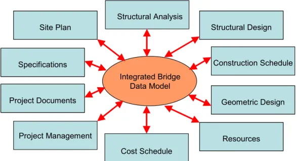
Bridge design projects involve a large number of highly inter-dependent activities that need to be efficiently managed and coordinated. An integrated data model can enable the efficient flow of information among various project activities. The integrated bridge data model can be used to represent and integrate information of different project aspect models (e.g. structural design, analysis, scheduling, estimating, etc.), and thus providing a comprehensive project data model that would bind together the multi-disciplinary perspectives of the project information, and therefore enhance the communication between the multi-disciplinary project teams. Multi-disciplinary project teams can use the integrated model to assess dependencies and interactions between different project aspects, and to evaluate decisions and resolve conflicts. Figure 1 explains the role of a standard bridge information model. The integrated project model plays an important role in ensuring the consistency and integrity of project data, and enabling efficient data sharing and exchange. The
integrated model can assist in identifying data inconsistencies, manage dependencies and interactions between different project disciplines, and communicating the data in an efficient and effective way. By explicitly modeling the relationships between various project entities, methods to determine whether any interdependent objects need to be updated as a result of a change can also be implemented.
Integrated Bridge Data Model Structural Analysis Construction Schedule Site Plan Site Plan Specifications Specifications Project Documents Project Documents Project Management Cost Schedule Geometric Design Geometric Design Structural Design Structural Design Resources Resources
Figure 1: Using a centralized shared data model to integrate bridge design processes
3 Developing a Core Information Model for Bridges
The main requirement for implementing integrated project systems in any domain is the availability of a data model that can model and integrate data across various project processes. The sheer size and complexity of data required to support bridge design activities makes the development of such a comprehensive data model a very challenging and expensive endeavour. To simplify the model development process, an approach typically known as “core models” is adopted to define a schema representing the “interfaces” or common data elements shared between various processes, with enough detail to support the integration and information flow between these processes. A major objective of this research is to define the scope and content of a Bridge Core Model (BCM) that can successfully support the integration of bridge design processes.
Similar to most other data standards, the development of the BCM schema was based on the ISO 10303 Standard for the Exchange of Product Model Data (STEP) [7]. The bridge EXPRESS model defines an integrated schema that represents the structure and organization of design data in the form of a class hierarchy. The schema defines entities such as alignment data, span arrangements, configuration of structural elements, loading data, materials properties, construction schedules, and cost items.
The full schema was decomposed to four main sub-schemas, each representing a specific aspect in the project. The sub-schemas included: structural design, structural analysis, construction scheduling, and cost estimating. The integrated bridge schema results from linking these sub-schemas through references among their entities in a consistent manner. A major advantage of using the schema integration approach is that various sub-schemas can be modified and maintained independently without impacting the rest of the data model. The first attempt in schema development involved the definition of all of these sub-schemas [3]. However, in light of the availability of more mature and complete schemas that cover the areas of structural analysis (CIS/2 schema [1]) and construction scheduling and cost estimating (Industry Foundation Classes, IFCs [6]), the effort has been focused on developing the Bridge Structural Design (BSD) sub-schema, and on integrating and harmonizing BSD with parts of the CIS/2 and IFC schemas. The CIS/2 structural analysis schema defines entities for finite element structural analysis, while the Industry Foundation Classes (IFCs) defines entities for construction scheduling and cost estimating as part of a complete schema for buildings projects.
The BCM consists of definitions of bridge structural entities, data types, and procedures, as well as rules that define the relationships among these entities. The BCM schema has been developed based on analysis of data from several projects and reviewing the information requirements of several structural applications. An entity is used to represent a class of a particular type such as beams, piers, etc. Figure 2 shows the EXPRESS-G diagram for the BCM schema indicating its structure and the entities relationships, as well as references to external schemas. The schema identified the basic structural elements of a typical bridge structure. The schema was defined, in a top-down strategy, as a decomposition hierarchy of structural entities. A schema that contains high-level abstractions was initially defined, and then lower-level entities were defined through successive top-down refinements. Specifically, a “Bridge” entity was defined at the top of the hierarchy, and the attributes of this entity were grouped into lower level entities and relationships (e.g. “Superstructure”, “Alignment”, etc.). All other entities in the model are accessible from the “Bridge” entity that represents the root of the entire schema. Relationships among different entities are described in the form of classification, association, and aggregation relationships. EXPRESS provides constructs to describe and represent each of these relationships.
Each entity in EXPRESS is described by a set of attributes. For example, a superstructure entity is described by its skew angle, spans, diaphragms, structural form, etc. An attribute value can be of simple, aggregate, or user-defined data type, which can be another entity. For example, the attribute “Has_Skew_Angle” of the “Superstructure” entity has a simple type “NUMBER”, while the attribute “Has_Spans” has an aggregate type (an array) whose elements have values of “Span” entity. Also, some attributes can be calculated or derived from other
attributes values. For example, the “Self_Weight” attribute of any structural object can be calculated given the attributes that describe its geometry and material type.
Bridge Span Beam Cross_Section Section_Properties Superstructure Project Part_of [1:1]
RC_Beam Steel_Beam Composite_Beam REAL Length [1:1] Pier Abutment Substructure Site Soil_Properties Soil_layer GWL Grid_reference Terrain_map Subsurface_Properties [1:1] Has_layers [1:n] Has_GWL [1:1] Bearings Has_Bearings [1:1] Deck Has_Deck [1:1] Pre-stressed_Beam NUMBER XSection_Location [1:1] Roadway_Surface Railing Drainage Alignment Vertical_Align ment Horizontal_ Alignment Location Parapet Foundation Has_Foundation [1:1] Has_Foundation [1:1] Coordinate_System Unit_System Curb Structural_Form Girder_Slab Truss Rigid_Frame Cantilever Orthotropic Box_Girder 1 Has_Structural_Form [1:1] Has_Coordinate_System [1:1] Has_Unit_System [1:1] Specifications Schedule Cost Estimate Documents Has_Properties [1:1] Has_Roadway [1:1] Has_Alignment [1:1] Horizontal [1:1] Vertical [1:1] Boundary_Conditions Has_Boundary_Conditions [1:1] Diaphragm NUMBER Has_Skew_Angle [1:1] Connected _To [2:?] Has_Transverse_Element [0:?] Section_Capacity Diaphragm_Props Has_Properties [1:1] Has_Capacity [1:1] Has_Railing [1:1] Has_Parapet [1:1] Has_Curb [1:1] Has_Drainage [1:1] Has_CostEstimate [1:1] Has_Schedule [1:1] Has_Specs [1:1] Has_Docs [1:n] Loads.Load_Case Loads.Load_Case CIS/2.Analysis_Model Analysis [1:1] Has_Structural_Form [1:1] Deck_Properties Has_Properties [1:1] Simple Continuous 1 Station Starting_Station [1:1] STRING Id_Name [1:1] Has_Address [1:1] Has_Grid_Reference [1:1] Has_Topology [1:1] Located_At [1:1]
Supporting _Abutments A[0:2] Has_Abutments A[1:2]
Has_Piers A[0:?]
Supporting _Piers A[1:2]
Has_Beams A[0:?] Has_XSection [1:1] Has_Load_Cases A[1:?] Has_Superstructure [1:1] Has_Substructure [1:1] Has_Spans L[1:?] 1
Figure 2. EXPRESS-G schema of the Bridge Core Model (BCM)
An entity type may have sub-types. For example, the “Beam” entity is further classified based on the beam material into “RC Beam”, “Steel Beam”, “Prestressed Beam”, or “Composite Beam” entities. Each of these sub-types can be further classified based on the beam structural form, and so on. The set of entities in each of these groupings is a subset of the entities that belong to the “Beam” entity. Each of these sub-types is called a “subclass” of the “Beam” entity type, and “Beam” is called the “superclass” for each of these subclasses. The relationship between a superclass and a subclass is often called an IS-A relationship, which signifies an inheritance or specialization/generalization relationship (a steel beam IS-A Beam). Association relationships between instances are represented in the form of object references. For example, a “Site” entity is associated with a “Bridge” entity by the “Located_At” attribute. Also, the relationship between a “Diaphragm” entity and its “Diaphragm_Properties” entity is represented by referencing the later entity as an attribute in the former entity. Aggregation relationships between instances are represented by containment of one or a group of some objects inside another object. For example, a “bridge” entity contains an “Alignment” entity, and a “Span” entity contains an array (or aggregation) of “Beam” entities. The EXPRESS code below shows the “Superstructure” and “Span” entity definitions.
ENTITY Superstructure Is_Part_Of: Bridge; Has_Structural_Form: (ONEOF Girder_Slab, Box_Girder, Orthotropic, Truss, Rigid_Frame, Cantilever); Has_Deck: Deck;
Has_Transverse_Elements: SET [0:?] OF Diaphragm; Has_Spans: ARRAY [1:?] OF Span;
Has_Skew_Angle: NUMBER; Has_Roadway: Roadway_Surface; Has_Railing: Railing; Has_Curb: Curb; Has_Parapet: Parapet; END_ENTITY; ENTITY Span Id_Name: STRING; Length: REAL; Starting_Station: Station;
Type: (ONEOF Simple, Continuous); Has_Beams: ARRAY [0:?] OF Beam; Has_Bearings: Bearings;
Supporting_Abutments: SET [0:2] OF Abutment; Supporting_Piers: SET [1:2] OF Pier;
UNIQUE Id_Name; END_ENTITY;
4 A Model-Based Project Data Repository for Integrated
Bridge Design
The project data repository contains the specific persistent design objects generated and consumed by different applications. The repository schema is created using the integrated data model described in Section 3. Typically, a repository can be implemented using simple neutral files, or using a centralized Database Management System (DBMS). File-based data exchange is known to be limited in its scalability and ability to manage a large volume of shared project information, or to support the
required data management functionality. Also, sharing project data using neutral files makes it difficult to control or track changes and versions of the data.
A centralized DBMS-based project repository is essential to support sharing and exchange of project information while being accessed concurrently by different users and applications. The DBMS helps to ensure data integrity and consistency across different applications. Users and applications can simply query the DBMS to retrieve the specific objects related to their respective views (e.g. structural objects, cost objects, etc.). The DBMS also enables the implementation of a variety of data management services that are typically required for large project systems. Besides the basic data management services, advanced functions such as version management, change management and propagation, concurrency control, security and authorization, and meta-data services, can also be implemented.
The project repository also supports data sharing and interoperability of various function-specific software applications. Existing function-specific legacy applications (e.g. structural design, analysis, scheduling, etc.) can be integrated into a unified environment to share and exchange project data. Applications that can natively support the repository’s data model will be able to simply plug into the environment. However, applications that do not support the repository’s native data model will require the use of an adapter to perform bi-directional data mapping. Depending on the specific application, adapters can be developed in several different ways. An adapter can be implemented as stand-alone software or as an add-on to the host application using any language or Application Programming Interface (API) supported by the host application to access the application’s object model.
5 Implementation of a Prototype Model-Based Bridge
Design System
A proof-of-concept prototype was implemented based on the model-based approach. The scope of the prototype was limited to support design of steel I-girder and concrete box girder bridges. A number of commercial software tools were used to support structural design and analysis (Sc-Bridge and GT-STRUDL) and construction scheduling (Primavera). Integrating commercial applications required the development of adapters to map their representation of the data to the schema implemented in the repository. Other tools have been developed to support geometric design, construction planning, quantity takeoff, and construction site modeling. These tools directly supported the proposed BCM data model, and therefore adapters were not needed for their integration.
5.1 Implementing the Project Data Repository
The project repository can generally be implemented using either a relational or an object-oriented DBMS. An object-oriented (OO) DBMS provides the functionality of a relational DBMS (e.g. persistence, concurrency control) in addition to the OO characteristics (e.g. inheritance, encapsulation). However, an OO DBMS is best
suited to support the modeling and manipulation of complex and nested structures. For example, in storing the bridge data, an OO DBMS can model the bridge as one object that contains and references a set of other objects such as piers, girders, etc., which simplifies data access and update. On the other hand, a relational DBMS will represent the objects, in a first normal form, in separate relations (or tables). For example, piers are stored in one table, girders in another table, and so on. Data related to different objects would need to be stored in different tables, which causes inefficiency in retrieving or updating these inter-related and complex objects.
EXPRESS schemas are independent of any DBMS technology, and therefore cannot be used directly to implement a database. Databases are built using a schema in a specific format supported by the database. Mapping the data model to generate a database schema is dependent on the modeling method, as well as on the specific DBMS. The schema mapping process was extensively studied in the literature, and a number of methods and tools that map EXPRESS models to relational or object-oriented schemas for a number of commercial DBMS were reported (e.g. [8]).
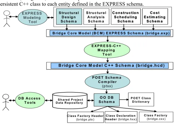
The project repository was implemented using a commercial object-oriented DBMS called Persistent Objects and Extended database Technology (POET), which is now known as FastObjects [10]. Creating the repository followed a two-step process. First, the BCM EXPRESS data model was mapped to a schema supported by the POET DBMS. Second, the data management functions of the underlying DBMS are then used to populate, query, and manage the repository. Figure 3 describes the implementation of these steps, and shows the schema mapping process and the files generated by the schema compiler.
To facilitate the first step, a schema translator was implemented to automatically map EXPRESS entities into POET persistent classes. The schema translator is based on the EXPRESS toolkit and EXPRESS Pretty Printing toolkit developed by the National Institute of Standards and Technology (NIST) [9]. The translator used calls to the Express Pretty Printing functions to translate the EXPRESS schema (stored in Bridge.exp file) to the POET C++ schema (Bridge.hcd file). The translator has three main phases. The first two phases perform parsing of the EXPRESS schema and create a symbol table and resolve references (similar to a compiler). These two phases create data structures, known as the Working Forms, that hold the data defined in the EXPRESS schema (entities, primitive data types, and aggregate data types, etc.). The third phase is used to write the POET database schema. This phase traverses the Working Forms data structures and generates the equivalent constructs in the database schema. The POET DBMS distinguishes between persistent and transient classes. The translator assumed all entities are persistent, and therefore all class definitions were preceded by the keyword “persistent.”
Database operations to update, query, and retrieve the object are defined automatically by the schema compiler. POET schema compiler generates standard C++ classes corresponding to the class declarations in the header file. The schema compiler (ptxx) uses as input the header file generated by our EXPRESS-C++
translator (Bridge.hcd) that contains persistent class definitions. This file defines a persistent C++ class to each entity defined in the EXPRESS schema.
S tru c tu ra l D e s ig n S c h e m a S tru c tu ra l D e s ig n S c h e m a B rid g e C o re M o d e l (B C M ) E X P R E S S S c h e m a (b rid g e .e x p ) B rid g e C o re M o d e l (B C M ) E X P R E S S S c h e m a (b rid g e .e x p ) S tru c tu ra l A n a ly s is S c h e m a S tru c tu ra l A n a ly s is S c h e m a C o n s tru c tio n S c h e d u lin g S c h e m a C o n s tru c tio n S c h e d u lin g S c h e m a C o s t E s tim a tin g S c h e m a C o s t E s tim a tin g S c h e m a E X P R E S S M o d e lin g T o o l E X P R E S S -C + + M a p p in g T o o l B rid g e C o re M o d e l C + + S c h e m a (b r id g e .h c d ) B rid g e C o re M o d e l C + + S c h e m a (b r id g e .h c d ) P O E T S c h e m a C o m p ile r (p txx) O O D B S c h e m a O O D B S c h e m a S h a red P ro je c t D a ta R e p o sito ry D B A c c e s s T o o ls C la s s F a c to ry (b rid g e .cx x ) C la s s D e cla ra tio n H e a d e r (b rid g e .hx x ) C la s s D e cla ra tio n H e a d e r (b rid g e .hx x ) C la s s F a c to ry H e a d e r (b rid g e .ptx ) C la s s F a c to ry H e a d e r (b rid g e .ptx ) P O E T C la s s D ic tio n a ry P O E T C la s s D ic tio n a ry
Figure 3. Mapping of the BCM EXPRESS schema to OO DBMS schema The schema compiler outputs three main files needed for the database schema: class declaration header file (Bridge.hxx), which contains persistent class declarations in standard C++; class factory header file (Bridge.ptx), which includes definitions for queries and container classes of persistent classes; and class factory file (Bridge.cxx), which defines in-memory constructors and destructors for persistent objects. The following example shows the definition of the “Superstructure” and the “Span” entities in the POET schema file. These definitions can be compared with the EXPRESS definitions of the two entities described in Section 3.
Persistent Class Superstructure {
Private: Bridge* Is_Part_Of; double Has_Skew_Angle; Deck* Has_Deck; lset<Diaphragm*> Has_Transverse_Elements; lset<Span*> Has_Spans; Roadway_Surface* Has_Roadway; Railing* Has_Railing; Curb* Has_Curb; Parapet* Has_Parapet; Public: Superstructure (); ~Superstructure();
Persistent Class Span {
Private: PtString Id_Name; double Length; Station* Starting_Station; lset<Beam*> Has_Beams; Bearing* Has_Bearings; lset<Abutment*> Supporting_Abutments; lset<Pier*> Supporting_Piers; //index on Id_Name useindex Id_NameIndex; Public: Span(); ~Span();
} }
indexdef Id_NameIndex : Span { Id_Name [[20]]; }
The POET DBMS supported a variant of the relational Structured Query Language (SQL), called the Object Query Language (OQL). The data management component used the OQL to populate and query the database. Similar to SQL queries, the OQL queries can be embedded in code, saved as stored procedures, or placed in a text file. The following is an example of an OQL that retrieves all span objects of a concrete box girder bridge stored in the repository and then searches for the span whose Id_Name attribute has the value of “Span 2” and finds the Starting_Station value of that span.
define extent allSpans for Span select i
from i in allSpans
s in i.Starting_Station
where i.Id_Name = “Span 2”
5.2 Example System Use Case
Structural Analysis Tools
3D Structural Model
Planning/Scheduling Tools
Structural Designer Structural Analyst Construction Planner
FEM Model Construction Schedule Cost Estimate Site Engineer Site Plan Site Engineering Tools Structural Design Tools Cost Estimating Tools Cost Estimator Integrated Project Data Repository
A p p l i c a t i o n s T i e r
Structural Analysis Tools 3D Structural Model Planning/Scheduling ToolsStructural Designer Structural Analyst Construction Planner
FEM Model Construction Schedule Cost Estimate Site Engineer Site Plan Site Engineering Tools Structural Design Tools Cost Estimating Tools Cost Estimator Integrated Project Data Repository
A p p l i c a t i o n s T i e r
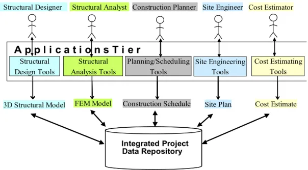
Figure 4. The use case of using the prototype integrate bridge design system The design process starts by defining the spatial features of the construction site using the site modeling application. Designers use the 3D site model to plan the bridge alignment and span arrangements. The structural design application uses the interactive 3D parametric design functionality to allow designers to interactively define the parameters of the bridge structural objects including the geometric and configuration data, the materials properties, and load data. Using the design data, the application prepares an Sc-Bridge data file and runs Sc-Bridge to generate a 3D finite element model by transforming the structural model into a set of members and elements. Using GT-STRUDL commands, the finite element model data files are loaded into GT-STRUDL, and a stiffness analysis is performed. The analysis results are saved in the GT-STRUDL internal database. The results are then extracted from GT-STRUDL database, using GT-STRUDL commands. Analysis results are extracted in a set of formatted text files. These results files include, for example, the displacement at x, y, and z directions at all joints, the rotation around x, y, and z axes at all joints, the stress and strain at the centre of each element, and the bending moment and shear values at each joint of a structural member. The generation of these files from GT-STRUDL is performed by running special GT-STRUDL commands. The analysis files are then processed to generate the data structures that are needed to support the interactive visualization of the analysis model and results.
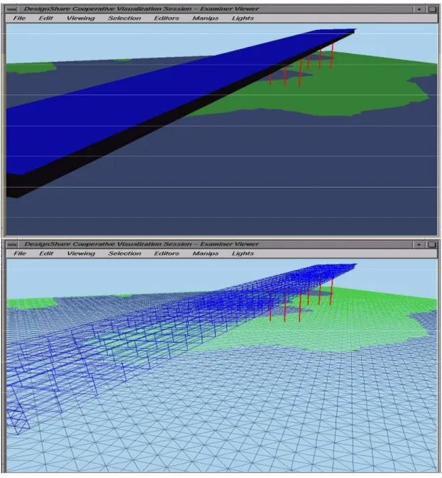
Figure 5. A shaded and wire-frame rendering of a concrete box girder bridge model After defining the bridge design parameters, construction planers and cost estimators use the design data stored in the repository, generate more objects, and link these objects with the design objects in the repository. Construction planners use the planning application to generate a preliminary construction logic plan and to interactively adjust this logic until it satisfies the project requirements. Plans can be modified by adding more activities, removing some activities, or changing the precedence relationships among activities. The planning application then prepares Primavera data files to perform scheduling calculations. The data files are loaded into Primavera and more data are entered to describe scheduling parameters such as the calendar to be used, the set of resources available, the duration of individual activities, and the number of resource units used by each activity. The application then performs the scheduling calculations. After performing the scheduling analysis,
planners can check if the project duration is within the specified requirement and whether the pattern of resource usage is within the capability of the contractor, and modify the schedule accordingly. Cost estimators also use the design data to calculate the quantities of concrete and steel for the bridge superstructure and substructure. The calculated values can then be input into a cost estimating software to calculate detailed cost schedules. Figure 5 shows an example of a 3D concrete box girder bridge model overlaid on a 3D triangulated irregular network (TIN) model of the construction site.
6 Conclusions and Future Directions
The bridge engineering industry is facing unprecedented challenges to improve the efficiency and quality of bridge design and construction projects. To address these challenges, the industry is currently undergoing a paradigm shift that emphasizes the integration of project processes throughout projects life cycle. However, the objectives of this integration can hardly be realized without the use of integrated and interoperable software systems.
This paper presented a model-based approach to enable the integration and interoperability of software systems used throughout the life cycle of bridge design and construction projects. The approach involves the use of an integrated data model and a centralized project data repository, where project data can be efficiently managed and shared between various applications and project actors. Making various aspects of project information accessible from a single repository significantly improves the flow of information across various project disciplines. An effort to develop a standard bridge core model (BCM), based on the ISO STEP standards, and to implement this model using an object-oriented DBMS was presented. Four main views (or sub-schemas) have been identified to support the core model: structural design, structural analysis, construction scheduling, and cost estimating. Because of the comprehensive nature of the bridge core model, the primary goal of future work would be to refine and extend the BCM schema, mainly for areas related to structural analysis, cost estimating, and construction scheduling. A more thorough investigation of applicable parts of the CIS/2 and IFC schemas in the context of the bridge core model is needed. Also, the prototype system needs to be enhanced and extended by using a more robust distributed object-oriented database that would enable concurrent access to project data.
Acknowledgements
We acknowledge the support of the Thomas French Fellowship program at the Ohio State University to this research project.
[1] CIMSteel Integration Standards (CIS/2), <www.cis2.org>, (Last Accessed: May 2005)
[2] Eastman, C.M. 1999. Building Product Models: Computer Environments Supporting Design and Construction. CRC Press, Boca Raton FL.
[3] Halfawy, M.R. (1998), “A Multi-Agent Collaborative Framework for Concurrent Design of Constructed Facilities,” Ph.D. Dissertation, Department of Civil and Environmental Engineering and Geodetic Science, the Ohio State University.
[4] Halfawy, M. and Froese, T., 2002. A Model-Based Approach for Implementing Integrated Project Systems, 9th International Conference on Computing in Civil and Building Engineering, Taipei, Taiwan, April 3-5, 2002. Vol. 2. pp. 1003-1008.
[5] Hisatomi, Yo, and Reismann, W. 1994. Design and Construct: Trend, Challenge, Improvement?. Journal of Structural Engineering International, No 3, Vol 4, 1994.
[6] IAI 2005. International Alliance for Interoperability, Industry Foundation Classes – IFC 2x. On-line documentation. http://www.iai-international.org (Last Accessed January 2005).
[7] ISO 10303-11, Industrial Automation Systems and Integration — Product Data Representation and Exchange — Part 11: Description methods: The EXPRESS language reference manual, International Organization for Standardization ISO, Geneva, 1994.
[8] Loffredo, David, Efficient Database Implementation of EXPRESS Information Models. PhD Thesis, Rensselaer Polytechnic Institute, Troy, New York, May 1998.
[9] National Institute of Standards and Technology (NIST), The NIST EXPRESS Toolkit, <www.mel.nist.gov/msidstaff/sauder/SCL.htm>, (Last Accessed May, 2005).