Publisher’s version / Version de l'éditeur:
Vous avez des questions? Nous pouvons vous aider. Pour communiquer directement avec un auteur, consultez
la première page de la revue dans laquelle son article a été publié afin de trouver ses coordonnées. Si vous
Questions? Contact the NRC Publications Archive team at
PublicationsArchive-ArchivesPublications@nrc-cnrc.gc.ca. If you wish to email the authors directly, please see the first page of the publication for their contact information.
https://publications-cnrc.canada.ca/fra/droits
L’accès à ce site Web et l’utilisation de son contenu sont assujettis aux conditions présentées dans le site LISEZ CES CONDITIONS ATTENTIVEMENT AVANT D’UTILISER CE SITE WEB.
7th International Conference and Exhibition on Performance of Ships and
Structures in Ice [Proceedings], 2006
READ THESE TERMS AND CONDITIONS CAREFULLY BEFORE USING THIS WEBSITE.
https://nrc-publications.canada.ca/eng/copyright
NRC Publications Archive Record / Notice des Archives des publications du CNRC :
https://nrc-publications.canada.ca/eng/view/object/?id=0b30d62c-11ff-4f8e-b16d-5ea5d3f3d370
https://publications-cnrc.canada.ca/fra/voir/objet/?id=0b30d62c-11ff-4f8e-b16d-5ea5d3f3d370
NRC Publications Archive
Archives des publications du CNRC
This publication could be one of several versions: author’s original, accepted manuscript or the publisher’s version. / La version de cette publication peut être l’une des suivantes : la version prépublication de l’auteur, la version acceptée du manuscrit ou la version de l’éditeur.
Access and use of this website and the material on it are subject to the Terms and Conditions set forth at
Mathematical modeling of ice-hull interaction for ship maneuvering in
ice simulations
Mathematical Modeling of Ice-Hull Interaction for Ship Maneuvering in Ice Simulations
Jiancheng Liu
P.O. Box 19, Faculty of Engineering and Applied Science, Memorial University of Newfoundland St. John’s, Newfoundland, Canada, A1B 3X5.
E-mail: Jiancheng.Liu@nrc.gc.ca Michael Lau
Institute for Ocean Technology, National Research Council of Canada, St. John’s, NL, Canada, A1B 3T5. E-mail: Michael.Lau@nrc.gc.ca
F. Mary Williams
Institute for Ocean Technology, National Research Council of Canada, St. John’s, NL, Canada, A1B 3T5. E-mail: Fmary.Williams@nrc.gc.ca
ABSTRACT
A new ice-hull interaction model using the analytical approach with numerical implementation for simulating various ship maneuvers in level ice is presented. Its simple physical detail and short computation time make it very suitable for real-time simulations. In the model, the icebreaking process was numerically simulated in the time domain. Three independent ice force components, the breaking, buoyancy and clearing forces, representing individual processes identified during a typical ice-hull interaction, are calculated separately and summed as the total ice force. The model is benchmarked against measurements from PMM model tests. A preliminary parametric analysis on the channel width and yaw moment due to the ship motions is carried out using the model. The simulation results demonstrate the capability of the model for the real-time simulations.
KEY WORDS: Ship maneuvering; Ice force; Ice-hull interaction model; Analytical model; numerical implementation
INTRODUCTION
Reliable modeling of ship maneuvers in ice is of great value for planning voyages, programming automatic pilot systems, and training ship operators. For applications such as training simulators and automatic pilot systems, the maneuvering model must be accurate, sufficiently detailed to provide the correct ‘feel’ to ship response, and numerically efficient to in order to provide results in real time. The model should also be general enough to simulate any specified maneuver, and adaptable to any ship.
In collaborative project between IOT and the Centre for Marine Simulations (CMS) a real time ship maneuvering in ice simulator is under development. A literature review showed that none of the published models satisfactorily met the simulator requirements: solution correctness, numerical efficiency and universality of application. Taking into account recent developments in ice engineering, a new ice-hull interaction model to satisfy the
This paper first presents a brief literature review of the existing models for the ship maneuvering in ice conditions. Then a new ice-hull interaction model is proposed and outlined. The model treats the ice-hull interaction process as a mechanical problem of global loads on a rigid body. Surge force, sway force and yaw moment on the hull caused by the ice are efficiently calculated. To demonstrate the capability of the model, four typical runs in model tests were simulated. A series of model tests carried out at IOT on the Canadian Coast Guard vessel Terry Fox were used to benchmark the numerical model. The resulting channel geometry and yaw moments on the ship are selected for discussion.
REVIEW OF EXISTING MODELS
Ship navigation in ice has attracted people’s attention for many years and considerable effort has been dedicated to modeling ship performance in ice conditions. Some of these models estimate the ice forces on the hull due to the ship navigation in level ice. Most of the models focus on resistance forces only.
In a large proportion of the available studies, some reasonable simplifications are made or empirical formulas are applied to model the complicated ice-hull interaction process, i.e. Lewis et al’s model (1982), Menon’s time domain model (1986), and Williams and Waclawek’s model (1998). In those models, the empirical coefficients were derived by fitting formulae to data from the model tests and full-scale trials. Due to the limitation of data available from model tests and sea trials, the expressions are simple, with few empirical constants. Hence there is a limitation on the application scope and expected accuracy of the model. A semi-empirical approach with theoretically derived mechanical formulae for calculating ice force components can take into account more detail of ship-ice interaction, i.e. Lindqvist’s model (1989) and Canmar’s steady turning model (Tue-Fee et al, 1987). Also, there are some analytical models adopting fully derived mechanical formulae, i.e. Kotras et al’s model (1983) and Lindstrom’s model (1991). Those models are more complicated and require more work to apply, but they are more universal, they manifest the physical concepts of ice-hull interaction and provide scope for improving the
constant radius turns. Menon’s time domain model and Williams and Waclawek’s model are both limited in accuracy and universality. Hence all fall short of the requirements of the CMS real-time simulator.
Numerical approaches have advanced with the development of the computer technology. They can be used to solve analytical equations, i.e. Lindstrom’s model, or to simulate the continuous ship-ice interaction process, i.e., Daley’s chaotic ice failure process model (1991). In Valanto’s model (2001), the finite difference method (FDM) is adopted to calculate the response of the level ice due to ship’s contact. In particular, two numerical approaches, finite element method (FEM) and discrete element method (DEM), which divide the continuous ice material into many small elements, are widely applied. These methods have good potential due to their more detailed modeling capability and good universality. However, there is more to be learned about the mechanical properties of ice before a satisfactory simulation of the breaking process is achieved. Moreover, the hardware requirements and the large calculation time present a challenge for real-time simulations.
The CMS simulator requires the simulations of arbitrary ship maneuvers in ice. Considering that none of the existing models can entirely satisfy its requirements, therefore, a new reliable ice-hull interaction model is introduced in the following.
DESCRIPTION OF THE MODEL
The model follows from a preliminary model presented in Lau and Derradji-Aouat (2004).
In the time domain, the ice breaking by the ship is comprised of the following processes: 1) the ice deforms with the relatively small deflection and some initial crushing failure at the ice edge. The vertical force on the ice keeps increasing until the ice flexural bending failure occurs and an ice cusp due to ice flexural bending failure is formed. In the case of thick ice or a structure with a large angle of incidence, the ice may be broken due to shear failure before the flexural bending failure. 2) The broken ice is rotated to be tangent to the wet surface of the hull. Ventilation above the rotating broken ice floes may occur due to the inability of the water to fill the void above the rotating ice floes. 3) Some ice pieces slide tangentially along the wet surface of the hull to the bottom and they leave the hull eventually. Others may slide to the ship side and be further acted upon by the hull.
The ice undergoes a similar physical process for each ice piece in both ship advance (resistance) and ship turning. From the macroscopic point of view, the amounts of the breaking ice on two sides of the longitudinal center section plane are different when the ship turns in the ice. This can cause an asymmetric force on the hull. Also, more parts of the hull may directly contact the unbroken ice compared to the ship advance case. Different ice failure modes may happen simultaneously from the stem to the stern along the waterline on the hull when the ship turns in the various level ice conditions due to the changing flare angle of the contact surface of the hull.
In the model, the ice force on the hull is calculated by the linear sum of the contributions from three independent ice force components, i.e., breaking force component, buoyancy force component and clearing force component, which respectively represent the corresponding physical phenomena during the ice breaking process as the following equation
F
ice=
F
br+
F
buoy+
F
cl (1) Where, Ficeis the total force,br
F
is the breaking force, Fbuoyis the buoyancy force andF
clis the clearing force.An overview of the ice-hull interaction model is given in Fig. 1.
Icebreaking force
The ice breaking force component represents the contributions from the ice breaking process. A time domain methodology is adopted to calculate the contact area between the hull and the unbroken ice and the channel is tracked through a simple house-keeping method. The ice-model first estimates the ice-hull contact area at the next step based on the current channel and the ship motion: displacement, velocity and acceleration, as the shown in Fig. 2. Then, based on the contact area and the ice mechanics, the ice breaking force is calculated. The new icebreaking area is applied to the previous channel to generate the new channel for next calculation step.
The actual ice crack patterns during the ship breaking ice process are stochastic and complex. The cusp pattern with the corresponding plate theory gives a reasonable representation of observed breaking patterns, and has frequently been applied in ice-hull contact models. The ice breaking pattern in the present model is patterned after Kotras et al (1983) as shown in Fig. 3.
Ice (Density, thickness, strength, etc)
Ice-hull contact and Ice pieces motion
Breaking force (Multi-failure
ice breaking model)
Forces from the ice pieces
Buoyancy force (Density difference) Clearing force (Velocity dependent)
∑
Linearsum Ship Motions (Displacement, velocity, etc) Hull Geometrics (Waterline, skew angles, underwater form, etc)Surge force, sway force and yaw moment Fig. 1 Ice force calculation model
X
Y
O
x
y
o
WaterlineFig. 2 Schematic of the ice-hull contact in the numerical framework
Channel width Ice edge at ‘i+1’ step Ice edge at ‘i’ step
The average breaking depth, D , is taken as 0.2 times the ice characteristic length (Lau et al, 1999). The width, W, is proportional to the cusp depth based on the full-scale trials (Kotras V., 1983).
h D
W= 10 (2) Where
h
is the ice thickness given in m.According to Kashtelyan (Kerr, 1976), the failure load,
P
f, to break off the two 90° wedges is2
518 .
0 h
Pf = σf (2)
where
σ
f is the flexural strength of ice;h
is the ice thickness. Besides flexural bending failure, the crushing failure is also considered as shown in Fig. 4. The crushing forcecrush
F normal to the ice-structure
contact surface is related to the nominal contact area, A, as (Sanderson, 1988);
A
P
F
crush=
0⋅
(3) Where, 0P is the compressive strength of ice.
Buoyancy force
The buoyancy force component represents the lift force from the ice pieces covering the hull due to the density difference between the ice and water. This is a velocity independent term. The time domain method is used to estimate the ice piece distribution over the wet surface of the hull during the ship’s maneuvers.
A flat-plate model is used to represent the underwater part of the ship for buoyancy force calculation, as shown in Fig. 5. Observations from
forces are then calculated by multiplying the volumes of the ice on the hull by density difference between ice and water. Ignoring the ice/hull friction, the ice forces on the hull are always normal to the contacting surface of the hull. Then the forces acting on the hull can be calculated using the balance of forces on the ice piece. The motion of the broken ice pieces on the hull is dependent on the ship geometry and the ship motions.
Clearing force
Representing different phenomena in the ice clearing processes, as shown in Fig. 6, the following ice force components may be included in the clearing force calculation: viscous drag and inherent buoyancy for the rotating ice floes, forces caused by wave pressure and ventilation of the rotating ice floes, and inertial forces due to the ice acceleration.
The energy method is adopted to calculate the ice mass inertial force. The inertial forces are identified as the forces that are required to accelerate the ice floes from zero speed to a sliding speed on the hull surface equal to the ship horizontal velocity divided by cosine of the angle,
Ψ
, as shown in Fig. 6. HereΨ
is the angle between the normal of the surface and a vertical vector. The horizontal force is equal to the kinetic energy of the ice floes with the added mass divided by the ship travel distance during the breaking cycle as the following equation.2 2 tan 5 . 0 Ψ = i n c hWV F ρ (4) Here i
ρ
is the ice density; W is the width of the structure; and V is the nstructural velocity in the direction normal to the ice-structure contact surface.
The added mass of the water excited during the ice piece turning process can be approximated using the following equation (Blevins, 1979): 8 2 D W Ma d d= ρwπ , (5)
where Wis the width of the ice cusp, D is the cusp depth of the ice cusp, and
ρ
wis the density of water.The ventilation phenomena above the turning ice piece due to the bow wave pressure and the hydrostatic pressure under the ice pieces was observed and studied by many previous researchers. In the present version, the forces due to the static pressure and bow wave under the turning ice piece are estimated using the theories of Enkvist (1972). Figure 3 Schematic the ice cusp pattern
Waterline W D
α
θ
B
T
η
Fig. 5 Simple model for buoyancy force calculation I’ I II II’ b l
a
Fig. 4 The ice breaking model
Hull
Flexural bending Crushing
Global force and moment
The whole hull is first divided into discrete segments and the breaking force and clearing force on each small segment are calculated. The final global force is the vectoral sum of the force components on all the small segments. The corresponding global yaw moments caused by the forces on all segments will also be calculated separately and linearly added together to arrive at the final yaw moments caused by the breaking force and clearing force. The global buoyancy force and resulting yaw moment are calculated directly based on the simple flat-plate model and added into the final total ice force and yaw moment on the hull.
Model verification
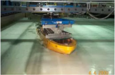
The model will be verified using the captive model tests. Captive model tests not only provide information for verification of the ice-hull interaction model, but are also valuable tools to develop and improve the theoretical model. The Institute for Ocean Technology, National Research Council of Canada (IOT/NRC) constructed a 90 meter ice tank in the 1980’s and a PMM (Planar Motion Mechanism) was installed in the 1990’s. Using the PMM apparatus in ice tank, the model motions in the horizontal plane, surge velocity, sway velocity and yaw rate, can be actually controlled and the global forces on the model, surge force, sway force and yaw moment, can be measured and recorded in time domain as shown in Fig. 7.
Fig. 7 The PMM Terry Fox Model Test (Lau, 2006)
PARAMETRIC AND QUALITATIVE OBSERVATIONS Accurate representation of the channel in the ice broken by the ship is a strong indication that the icebreaking process is being correctly modeled. It is also important in the simulation applications for icebreakers performing escort operations. Furthermore, the energy to break the ice, and hence the resistance force, is a function of broken channel area (Tue-Fee et al, 1987; Lau and Derradji, 2004) and hence a useful design parameter. The yaw moment is the key factor that decides the limiting ice condition for ship turning and the ship maneuverability. Yaw moments due to different yaw rates and drift angles are easily calculated by the model. Hence for this preliminary analysis of model results, channel width and yaw moment are selected as the parameters to consider.
In the following, the model is applied for the hull form of the Terry Fox and the ice conditions from a set of recent maneuvering experiments conducted in IOT (Lau, 2006). The segmented water line width and the flare angles at those positions of the Terry Fox model are given in Table 1. The target ice thickness and flexural strength were 40 mm and 35 kPa, respectively.
Table 1 IOT Terry Fox model hull section data Location (m) Draft (m) WL Width (m) Angle
Ψ
(°) 3.440f 0.368 0.037 23.3 3.096f 0.368 0.265 24.5 2.752f 0.368 0.389 24.5 2.408f 0.368 0.393 31.5 2.064f 0.368 0.396 80.5 1.720f 0.368 0.396 80.5 1.376f 0.368 0.396 80.5 1.032f 0.368 0.395 80.5 0.688f 0.368 0.389 24.5 0.344f 0.368 0.370 24.5 0.000 0.368 0.294 24.5Two coordinate systems, i.e., the global coordinate system and the moving coordinate system, are used to depict the ship motion and the force on the ship. The global coordinate system is static. The moving coordinate system is fixed to and moves with the ship. Its origin always stays at the center of the ship’s center of gravity. The surge (x)-axis is positive in the direction of the bow and the sway (y)-axis positive pointing towards starboard.
Constant Radius Turns
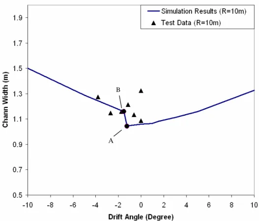
A series of constant radius turns at 10 m radii and different drift angles are simulated with the fixed pivot point at the mass center of the ship. The corresponding channel widths are presented in Fig. 8. As might be expected, the drift angle, β, has a major influence on the broken channel width created by the ship. Fig. 8 also shows the measured channel widths in the model tests (Lau, 2006). The figure shows that simulated channel widths are acceptable to a preliminary model. The differences between the simulations and measurements are logically due to the assumptions about piece size in present version of the model. Hence piece size estimates will be refined in the subsequent version. Fig. 6 Schematic of the ice piece turning and sliding
Water Hull Level Contact Ventilation O t Vn* n V
n V
Wave and hydrostatic pressure
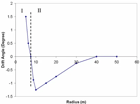
Overall, the channel width vs. drift angle curve shows a “V” shape. In the 10 m circle, the sharp increase in channel width occurs as the stern first contacts the channel edge (at A), and then, with a slight increase in drift angle, breaks a piece at the channel edge (at B). For constant radius turns, the drift angle that causes the smallest channel width may be nonzero. The drift angles generating the smallest channel widths at different turn radii are calculated and re-plotted in Fig. 9. The two parts of the curve in Fig. 9 indicate two different breaking processes. In part I, with negative drift angle, the stern always breaks the ice. In part II, The drift angle at which the stern contacts the unbroken ice decreases with the increase of turning radius. At large radius, minimum channel width nearly corresponds to zero drift angle. That means a very little drift angle will cause the stern to break the ice. The drift angle dividing the curve of the Fig. 11 into I part and II part is dependent to the ship geometry and the ice properties.
The effect of drift angle on yaw moment was investigated through a series of simulations of constant 10 m radius turns with 0.1, 0.3 and 0.6 m/s velocity and –10°~10° drift angles. The simulation results are given in Figure 10. Again, the sharp increase in yaw moment from drift angle –1.25° to drift angle –1.5° occurs as the stern begins to break ice at the edge of the channel.
Apart from stern contact, the influence of drift angle on final yaw moment is due to the change in the contact zone between the ice and hull, which in turn causes a change in the ice breaking force distribution over the whole hull. In fact, with increase of the drift angle, a greater part of the hull side including the stern will directly contact the unbroken level ice and the location of the ship turning pivot may change. In the current simulations, the turning pivot is fixed at the mass center of the ship in the simulations. Simulations for free running ship motions would result in a different contact zone.
Fig. 8 The channel widths vs. drift angles
A B
Fig. 9 The narrowest channel widths vs. drift angle in the different radius turning runs
I
II
Fig. 10 Yaw moment in turning circles (R=10m)
Pure yaw and pure sway
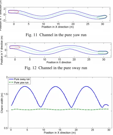
Two idealized PMM model test runs - pure yaw run and pure sway run - for the Terry Fox model in level ice are simulated in order to showcase the capability of the model to simulate arbitrary maneuvers in level ice.
Fig. 11 and Fig. 12 show the channel geometry for the two runs. The channel widths are plotted against time in Fig. 13. Fig. 14 and Fig. 15 show the yaw moments in two runs. The phase of yaw moment curve in pure yaw run shows one quarter of period difference to that in pure sway run. Although, the yaw moments in both runs are approximately between ±55N*m, the force causes are different. In pure yaw run, the bow and some stern contacting the unbroken level ice produce the major contributions to the final yaw moment. In the pure sway run, most of the hull side directly contacts the unbroken level ice and the final yaw moment is determined by the different geometry of the aft- and fore-body of the hull.
In open water conditions, the yaw moment is linearly proportional to small variations of the ship motion. The corresponding stability derivatives, i.e. yaw moment to sway velocity, yaw moment to yaw rate, can be obtained from pure yaw and pure sway runs. However, the ship maneuvering in level ice is actually a solid-solid interaction process that is different from fluid-structure interaction. The simulated yaw moment of the those two runs in level ice shows a complicated shape, which indicates the yaw moment is not linear in the ship motion parameters.
This paper presents a work in progress. To verify the model, the qualitative and quantitative simulation results will be compared with the results of the Terry Fox results referenced here as well as model and full scale measurements on other hull forms.
Fig. 11 Channel in the pure yaw run
Fig. 12 Channel in the pure sway run
Fig. 14 Yaw moment in the pure yaw run
Fig. 15 Yaw moment in the pure sway run
SUMMARY AND CONCLUSIONS
1) The new ice-hull interaction model treats ice-hull interaction as a mechanical problem and faithfully models the physical details of the interaction. Hence it gives realistic forces and ship motions. The analytical approach yields a short computation time. Hence the proposed ice-hull model is very suitable for the real-time simulations.
2) A preliminary parametric analysis with the qualitative discussion on the channel geometry and yaw moment on the hull due to the ship motions in level ice was carried out. The simulation results show reasonable trends. The drift angle strongly influences ice-hull contact area and the yaw moment on the ice-hull. The channel width and final yaw moment in the constant radius turns are sensitive to whether or not the stern breaks the level ice. The channel width varies over a large range during the pure sway run, while it remains relatively constant in pure yaw run. The yaw moment curves in two runs shows the yaw moment may not be linear to the small variations of ship motions.
3) A preliminary version of the ice-hull interaction model has been presented. Planned refinements include: based on the available PMM model tests, a more detailed ice breaking failure process; the ship velocity effect on the ice piece size; the buoyancy force based on the real underwater form of the hull; enhanced hydrodynamics in the clearing force calculation; and the fictional drag force on the ship.
ACKNOWLEDGEMENTS
This work was supported by the Institute for Ocean Technology and the Atlantic Innovation Fund through the Modeling and Simulation of Harsh Environments Project.
REFERENCES
Blevins R.D., “Formulas for Natural Frequency and Mode Shape”,
Copyright by Van Nostrand Reinhold Company, Inc., New York, USA, 1979
Daley, C. “Ice Edge Contact - A Brittle Failure Process Model”, Acta
Kerr, A. “The Bearing Capacity of Floating Ice Plates Subjected to Static or Quasi-Static Loads”, Journal of Glaciology, Vol. 17, No.
76, 1976.
Kotras, T.V., Baird, A.V., and Naegle, J.W., “Predicting Ship Performance in level Ice”, Trans.SNAME, Vol.91, p.329-349, 1983. Lau, M. “Preliminary Modeling of Ship Manoeuvring in Ice Using a PMM”, Institute for Ocean Technology Report, 2006.
Lau, M., Molgarrd, J., F. M. Williams and A.S.J. Swamidas, “An Analysis of Ice Breaking Pattern and Ice Piece Size around Sloping Structures”, POAC’99, St. John’s, NL, 1999.
Lau, M. and A. Derradji-Aouat, “Preliminary Modeling of Ship Maneuvering in Ice”, 25th Symposium on Naval Hydrodynamics, St. John’s, CANADA, 2004.
Lewis, J.W., Frank, W.D., Vanya, A.B., “Resistance and Propulsion of Ice-Worthy Ships”, TRANS. SNAME, Vol. 90, 1982.
Lindqvist, G., “A Straightforward Method for Calculation of Ice Resistance of Ships”, POAC’89, Lulea, Sweden, pp722-735, 1989.
Lindstrom, C.-A, “Numerical Estimation of Ice Force Acting on Inclined Structures and Ships in Level Ice”, Proceedings of 22nd
Offshore Technology Conference, OTC 6445, Houston, Texas, pp209~216, 1991.
Menon, B., Edgecombe, M., Tue-fee, K., Glen, I., “Maneuvering Test in Ice Aboard USCGC Polar Star in Antarctica 1985”, Arctec
Canada Limited, Report, Ontario, Canada, 1986.
Tue-Fee, K., Keinonen, A.J., Menon, B.C., Bayly, I.M., “Model for Predicting the Steady Turning Performance of Conventional icebreakers in Level Unbroken Ice”, Proceedings of the
International Conference on Ship Maneuvrability, 1987.
Valanto, P., “The Resistance of Ships in Level Ice”, SNAME
Transactions, Vol. 109, 2001,
Williams, F.M. and Waclawek, P., “Physical Model Tests for Ship Maneuvering in Ice”, Proceeding of the 25th
American Towing Tank Conference, Iowa, 1998.