Publisher’s version / Version de l'éditeur:
Questions? Contact the NRC Publications Archive team at
https://publications-cnrc.canada.ca/fra/droits
L’accès à ce site Web et l’utilisation de son contenu sont assujettis aux conditions présentées dans le site LISEZ CES CONDITIONS ATTENTIVEMENT AVANT D’UTILISER CE SITE WEB.
Laboratory Memorandum (National Research Council of Canada. Institute for Ocean Technology); no. LM-2005-08, 2006
READ THESE TERMS AND CONDITIONS CAREFULLY BEFORE USING THIS WEBSITE. https://nrc-publications.canada.ca/eng/copyright
NRC Publications Archive Record / Notice des Archives des publications du CNRC :
https://nrc-publications.canada.ca/eng/view/object/?id=1187a288-150d-4a2b-92b4-d990d06b3263 https://publications-cnrc.canada.ca/fra/voir/objet/?id=1187a288-150d-4a2b-92b4-d990d06b3263
Archives des publications du CNRC
For the publisher’s version, please access the DOI link below./ Pour consulter la version de l’éditeur, utilisez le lien DOI ci-dessous.
https://doi.org/10.4224/8894845
Access and use of this website and the material on it are subject to the Terms and Conditions set forth at Marine icing system modifications to system 2
TABLE OF CONTENTS
List of Figures ... iii
List of Tables ... iii
INTRODUCTION ...1
DEPLOYMENT INSTRUCTIONS FOR PHASE 2 (2004) OF THE MARINE ICING PROJECT ...2
Special Connectors ...2
Special Connections...2
Powering Up the System ...2
Connection Diagram / Images ...3
CONNECTION...19
WIRING DIAGRAM...20
WIRE COLOR...20
PIN NUMBER ...20
DESCRIPTION ...20 Appendix A: Power Supply Modifications
List of Figures
Page
Figure 1 - Connection Diagram ...3
Figure 2 - Power Enclosure (Outside)...5
Figure 3 - Power Enclosure Main Switch ...6
Figure 4 - Power Enclosure (Inside)...7
Figure 5 - Computer Enclosure (Outside). ...8
Figure 6 - Battery UPS Switch. ...9
Figure 7 - Computer Enclosure (Inside). ...10
Figure 8 - Ethernet/data connection between the cameras and the computer inside the computer enclosure. ...11
Figure 9 - Satellite Phone. ...12
Figure 10 - Camera Enclosure (Outside). ...13
Figure 11 - Camera Enclosure (Inside). ...14
Figure 12 - Camera Enclosure (Wiper). ...15
Figure 13 - Water Reservoir...16
Figure 14 - Computer to Camera Cable...17
Figure 15 - Power Enclosure to Computer Enclosure Cable...18
List of Tables
Page Table 1 - Connector List...19INTRODUCTION
This report describes the wiring modifications which were made to the second of two environmentally controlled dual still camera systems which were purchased through PERD Project 42_836_16 from a commercial vendor to study the accretion of ice on Marine Vessels or Structures.
The system consists of 2 still cameras enclosed in separate environmental
housings, an embedded camera control PC and associated peripherals enclosed in an environmental enclosure, a power supply enclosure, and a commercial satellite phone with an environmental enclosure.
The system is meant to be deployed into the field for periods of 1 to 2 years. The still camera images are stored on 2 hard disk drives simultaneously for
redundancy purposes and the images are taken at preprogrammed intervals. Images are transferred off the system by connecting an external laptop pc at the deployment site.
The purpose of the satellite phone is to periodically monitor the status of the system. The satellite phone data transfer rate is very slow and thus transfer of the high resolution images captured by this camera system in “real time” is not possible.
To enable greater flexibility in deploying this system in the field it was decided to add connector sets at each environmental enclosure so that each cable which enters or exits the enclosure can be disonnected. Because of the expected deployment environment, these connector sets were sealed against water / moisture ingress.
An added modification to this system was performed to enable the system to be powered from 120Vac or 240Vac input power at the deployment site.
DEPLOYMENT INSTRUCTIONS FOR PHASE 2 (2004) OF THE MARINE ICING PROJECT
Special Connectors
Network cables are used to transport data to and from the cameras. These network cables have fragile connectors on each end, which may easily be broken. Great care should be taken when handling these. It is recommended
that these types of connectors be wrapped in electrical tape to help prevent damaging the ‘key’ until they are ready to be inserted into the proper jacks.
These cables also required the use of larger glands so as to permit the connector to pass through. Because of this, a small area of the cable’s diameter has been built up. This will allow the gland to more snuggly tighten down over the cable. It is important to be sure that the built up area of the cable is actually in the gland before tightening the gland down. Glands are located at connections 2, 4, 11, and 13. Do not over tighten the glands; the material used to build up the diameter of the cable may break.
Special Connections
Connections 8, 9, 18, and 19 also require special attention when setting up the system in the field. These connections are not located directly at the enclosures but are located approximately 18” away, on the cable itself. These connections should be weatherproofed after they are made. To do this it is recommended to tightly wrap the connection in vulcanizing tape after it has been completed. Also, after these connections have been made they should be secured to the camera enclosure to prevent blowing/moving around in the wind/weather.
Powering Up the System
Once all the connections have been made it is safe to turn the system on. Please follow these steps to insure a trouble free power up:
• Check all connections to insure that they are done correctly.
• Check the position of the main power switch on the power enclosure and make sure it is in the off position.
• Check the position of the battery switch on the computer enclosure and make sure it is in the off position.
After a few minutes the system will be powered up and acquiring images. To check the system’s functionality on-site, connect a laptop to the computer enclosure’s exterior network connection using a crossover cable (see page 6).
Connection Diagram / Images
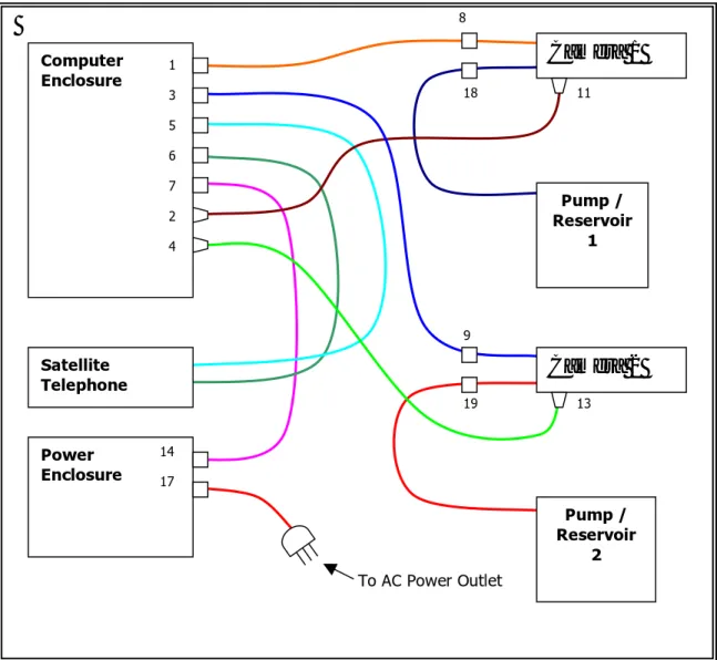
The following pages detail the connections, wiring diagrams, and connector diagrams for the complete system. Figure 1 provides an overall connection diagram, Table 1 provides a connector list, and Table 2 provides a wiring
diagram. A red square with a labeled red circle inside indicates more information is available about that particular area of the photo.
Connection Diagram 8 To AC Power Outlet Camera 1 Pump / Reservoir 1 13 11 Camera 2 Pump / Reservoir 2 9 19 18 Computer Enclosure 3 4 2 7 6 5 1 Power Enclosure 17 14 Satellite Telephone
Completed System Pictures
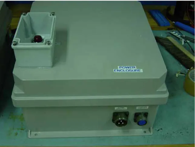
Figure 2. Power Enclosure (Outside).
Connections made in this picture:
• 14 • 17
Other information:
B
C
A
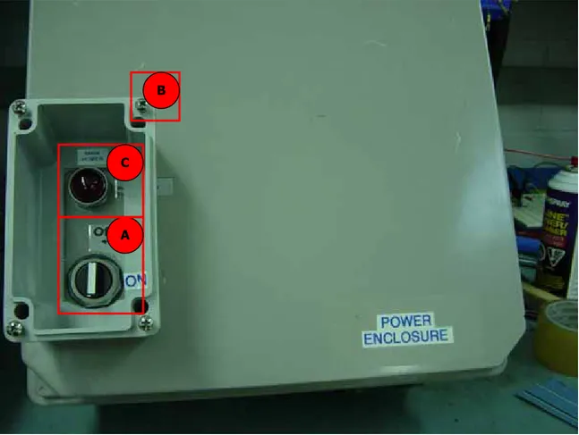
Figure 3. Power Enclosure Main Switch
Connections made in this picture:
• N/A
Other information:
A. This will be the first switch you turn on when starting the system in the field.
B. The waterproof cover is attached via four screws. Insure these are
securely attached when system initialization/checking is finalized.
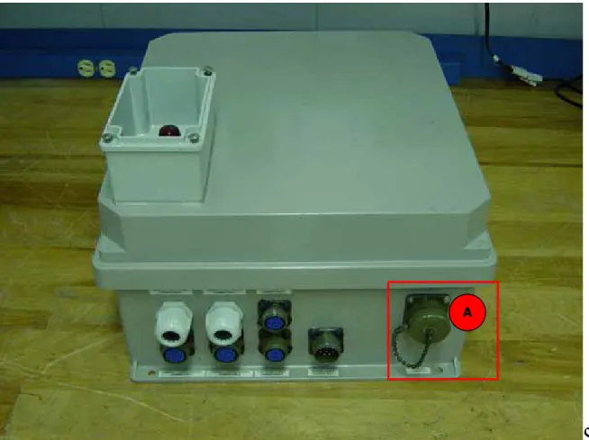
Figure 4. Power Enclosure (Inside).
Connections made in this picture:
• N/A
Other information:
A
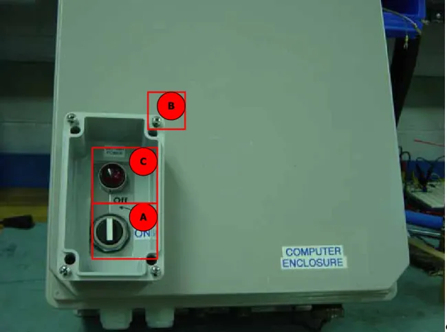
Figure 5. Computer Enclosure (Outside).
Connections made in this picture:
• 1 • 2 • 3 • 4 • 5 • 6 • 7 Other information:
B
C
A
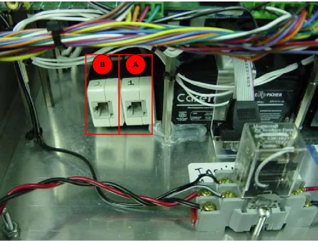
Figure 6. Battery UPS Switch.
Connections made in this picture:
• N/A
Other information:
A. This switch enables the battery backup (UPS) system. When this switch is enabled the computer will do an orderly shutdown in case of power failure to the system. This switch should be enabled in normal
circumstances.
B. The waterproof cover is attached via four screws. Insure these are
securely attached when system initialization/checking is finalized.
C. This light will be lit when the switch to enable orderly shutdown is turned to the ON position.
A B
Figure 7. Computer Enclosure (Inside).
Connections made in this picture:
• N/A
Other information:
A. Mouse/Keyboard Connectors used when you need to operate the system locally.
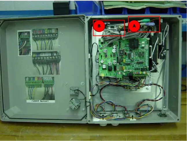
A B
Figure 8. Ethernet/data connection between the cameras and the computer inside the computer enclosure.
Connections made in this picture:
• N/A
Other information:
A. The Ethernet/data connection for camera 1 (connection 2) plugs in here. B. The Ethernet/data connection for camera 2 (connection 4) plugs in here.
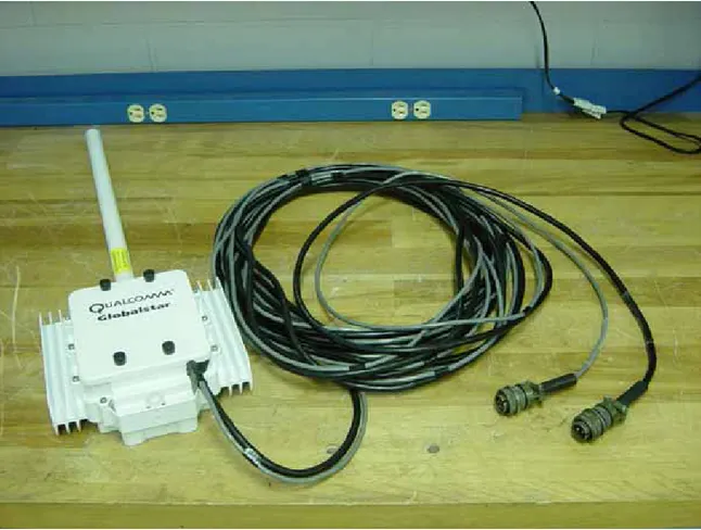
Figure 9. Satellite Phone.
Connections made in this picture:
• 5 • 6
Other information:
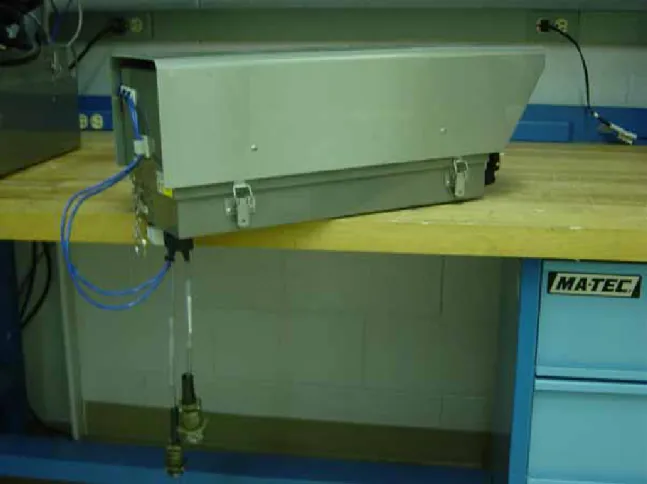
Figure 10. Camera Enclosure (Outside).
Connections made in this picture:
Camera 1: • 8 • 11 • 18 Camera 2: • 9 • 13 • 19 Other information: A. N/A
A
B
Figure 11. Camera Enclosure (Inside).
Connections made in this picture:
• N/A
Other information:
A. Connect the Ethernet/data cable here.
B. The Ethernet/data cable passes through the gland and into the camera enclosure here. The cable diameter has been built up here to
A
Figure 12. Camera Enclosure (Wiper).
Connections made in this picture:
• N/A
Other information:
A. Release this set screw to remove the wiper blade. Removing the wiper blade will make it easier to open and work on the inside of the camera enclosure. You will need a 3mm Allan Key to release this set screw.
B
A
Figure 13. Water Reservoir.
Connections made in this picture:
Pump/Reservoir 1: • 18
Pump/Reservoir 2 • 19
Other information:
A. This end of the hose hooks up to the sprayer on the camera enclosure. B. Note that there are two of these reservoir/pumps, one for camera 1 and
B
A
Figure 14. Computer to Camera Cable.
Connections made in this picture:
Camera 1: • 1 • 2 • 8 • 11 Camera 2: • 3 • 4 • 9 • 13 Other information:
A. The cable diameter has been built up here to accommodate a large sized gland. Do not over tighten gland.
A
Figure 15. Power Enclosure to Computer Enclosure Cable.
Connections made in this picture:
Computer enclosure: • 7
Power enclosure: • 14
Other information:
A. This is a heavy cable and care should be taken when finding somewhere to place it. Prevent twisting and kinking of the cable.
Connector List
CONNECTION Description Connector Pins Box or Cable Mount Socket or Pin
97-3102A-18-1S Box Socket
1 Camera 1 power/control
97-3106A-18-1P 10 Cable Pin
2 Camera 1 (RJ45) gland N/A Box N/A
97-3102A-18-1S Box Socket
3 Camera 2 power/control
97-3106A-18-1P 10 Cable Pin
4 Camera 2 (RJ45) gland N/A Box N/A
97-3012A-16-11S Box Socket
5 Satellite telephone power
97-3106A-16-11P 2 Cable Pin
97-3102A-16S-1S Box Socket
6 Telephone data (serial port)
97-3106A-16S-1P 7 Cable Pin
97-3102A-18-1P Box Pin
7 System power
97-3106A-18-1S 10 Cable Socket
97-3106A-18-1S Cable Socket
8 Camera 1 power/control
97-3100A-18-1P 10 Cable Pin
97-3106A-18-1S Cable Socket
9 Camera 2 power/control
97-3100A-18-1P 10 Cable Pin
11 Camera 1 data (RJ45) gland N/A Box N/A
13 Camera 2 data (RJ45) gland N/A Box N/A
97-3102A-18-1P Box Pin
14 System power
97-3106A18-1S 10 Cable Socket
97-3102A-22-2P Box Pin
17 AC power connection
97-3106A-22-2S 3 Cable Socket
97-3106A-14S-1P Cable Pin
18 Pump 1 power/control
97-3100A-14S-1S 3 Cable Socket
97-3106A-14S-1P Cable Pin
19 Pump 2 power/control
97-3100A-14S-1S 3 Cable Socket
WIRING DIAGRAM
Connection WIRE COLOR PIN NUMBER BLACK A BLUE B YELLOW C GREEN D WHITE E ORANGE F BROWN G RED H 1, 3, 8, 9 PURPLE J RED A 5 BLACK B BLACK A BROWN B WHITE C GREEN D RED E
ORANGE F Wiring Inside Enclosure
6
BLUE G Wire Color DESCRIPTION
BLACK A BLUE
BLACK W/WHITE B BROWN
WHITE C WHITE
GREEN D BLACK
ORANGE E YELLOW
BLUE F ORANGE
WHITE W/BLACK G RED
RED W/BLACK H GREEN
MAIN POWER
RED J BLACK (-)
7, 14
GREEN W/BLACK K RED (+)
SAT. PHONE POWER TO RELAY BLUE A BROWN B 17 GREEN W/YELLOW C BLACK A 18, 19 RED B
Connection 2, 4, 11, and 13 are gland connections.
APPENDIX A
M
ARINEI
CEM
ONITORINGS
YSTEM#2 P
OWERS
UPPLYM
ODIFICATIONSI
NTEGRATIONO
FA
S
TEP-D
OWNT
RANSFORMERF
OR120/240 V
O
PERATION1.0 I
NTRODUCTION1.1 B
ACKGROUNDCurrently at National Research Council Canada’s Institute for Ocean Technology (NRC-IOT) an ice monitoring system has been developed to monitor the accumulation of ice on ships. The ice monitoring system is currently being prepared for installation on board a supply vessel for application in a harsh environment. However some modifications to the system are necessary to make the system ready for installation on the actual ship.
1.2 P
ROBLEMThe modifications to be made to the system involve alterations to the power enclosure to support dual supply voltage operation. Currently the system is wired to operation from a 120 VAC, 60 Hz source. The vessel the system will be installed on has a 208 VAC power system running at 60 Hz. Therefore the power enclosure will need to be modified to accommodate a 208V/120V step-down transformer so that the system can be
integrated into the ships power system. Additionally since the system is likely to be ported to other ships running on 120 V power it is necessary to maintain the current power supply configuration. This was done using a double pole double throw (DPDT) switch to serve as a voltage selector.
During the installation of the above modifications, a number of deficiencies were noted in the current construction of the system. These issues needed to be addressed before the system could be deemed safe to install. The problems identified are noted below. When examining the existing wiring of the system it was noted the ON/OFF power switch was wired into the neutral of the main input line. This presented a potentially unsafe condition since when the system is shut off all components will be ‘hot’ (above ground potential). A fault to ground could allow current to flow, and possibly cause the system to become active.
The second problem was that all over-current protection in the power supply was located on the secondary side of the 120V/24V step-down transformers. There was no such protection on the primary side of the system. Any fault in the primary would cause damage to the power supply and potentially cause a fire if the shipboard protection
2.0 S
YSTEMM
ODIFICATIONSThe layout of the power enclosure was rearranged to accommodate the new step-down transformer. A new DPDT slider switch was integrated to allow selection of the input voltage level. The main power transformer was moved to allow sufficient space for the 208/120 step-down transformer. The enclosure layout before and after the modifications is shown in figures 1, and 2 respectively.
Figure 16: Layout Before Modifications
20 VAC Test
115 VAC Test Input Power
24 VAC Test
Additionally the five point terminal block was replaced with a twelve-point block. Jumpers were added to short the terminals into two six-point buss bars. This was to provide multiple points for connecting the output transformers and thus provide for cleaner wiring.
While the enclosure was undergoing these modifications some issues arose with respect to the standard wiring techniques.
First the main power switch was wired into the neutral line, normal practice wires power switches into the hot line since the neutral is typically connected to ground potential at the main panel. In this condition with the switch in the off position the system
components remain live even though the system is not running. The switch was rewired into the hot line to address this issue.
The next problem that arose was that all the overcurrent protection circuitry was located on the secondary side of the power supply. There was no such protection on the primary side of the power enclosure, and a fault in the primary could cause a fire within the enclosure. Fusing the hot and neutral input lines of the power enclosure solved this problem.
Finally it was recommended that a new double pole single throw main power switch be purchased to break both the hot and neutral lines to completely disconnect the system from the power source. This is due to the fact that most shipboard distribution systems do not ground the neutral line. Thus there are actually two hot lines in the system, and disconnecting only one line would still leave the system live and pose a shock hazard. By adding the switch to break both lines the system is now rendered electrically dead and safe.
With these modifications complete a new 100’ power cable was also made to carry 208 V AC power. The cables and connectors were potted for waterproofing. The system is meant only to run on 120 or 220 VAC power and does not have dual voltage inputs. Therefore it is imperative that the operator/installer be certain the voltage select switch is in the correct position for the available operating voltage.
Upon examination of the complete Marine Icing Monitoring system it was discovered that the satellite phone was insufficiently waterproofed (The satellite phone had been previously used in a past project). There was evidence of water penetration inside the unit through the cable pass-through in the bottom of the casing, and at the screw holes, which hold the cover in place. To fix this the cable entry point was sealed with flange sealant, and there were o-rings placed over the screws to provide better sealing. Then all the o-rings and gaskets were covered with a film of vacuum grease to prevent them from drying out, and the cover was replaced back on to the phone. These measures should
Table 3: Parts List
Part Number Description Manufacturer Vendor
SJOOW 100' 14-3C PORTABLE CORD Carol Anixter
BST-001 NC Contact Block for ASD211N Switch IDEC WESCO Distribution BST-010 NO Contact Block for ASD211N Switch IDEC WESCO Distribution 91F8306 97-3106A-22-2S Connector Backshell AMPHENOL Newark
96F4879 97-3057-1012-1 CABLE CLAMP W. BUSHING AMPHENOL Newark 46F1695 V80212SS05Q DPDT Select Switch C & K Newark
12 Position Terminal Block With Jumpers Any Any
Fuses 5 A, 240 V Any Any
Dual Fuse Holder Any Any
THG500W 500W 120/240 Step-up/down Autotransformer AED International Voltage Converters.com
3.0 T
ESTSUpon completion of the modifications to the power system, functional checks to ensure proper system operation were carried out. First the power enclosure was powered up unconnected to any other components in the Ice Monitoring system. The transformer outputs at various points were verified using a DMM. CAUTION: There are dangerous voltage levels present inside this enclosure so proper care should be taken when probing the system. The output side of the voltage converting transformer should read 115 VAC ± 5 V, the output of the main power transformer should be 24 VAC ± 2 V, the smaller secondary transformers should read 20 VAC ± 2 V. The test points are highlighted in figure 2.
Once proper power supply operation was verified the entire system was setup and run for at least one day. All components were checked for proper operation including the
computer system, the satellite phone, the cameras, and wiper/washer system.
4.0 C
ONCLUSIONSand
R
ECOMMENDATIONSThe work completed as noted above provide increased versatility for the Marine Icing Monitoring System, and extends its application to a wider variety of ships (and thus a greater variety of sea conditions). The second system (or rather the first system that was tested on board the MV Caribou) has not yet been modified to support dual voltage operation. This system will also require the same modifications as above. Given timely availability of materials, and following the changes to the system as discussed above, it is expected the work can be performed in two working days (provide there are no
significant differences between the two systems).
During full system testing performed by Wayne Pearson, he noted that it was not possible to run both the wipers and the washer pump motors at the same time. This problem can be adjusted for by avoiding running the devices at the same time. However future