Alcator C-Mod Soft X-Ray Pulse Height Analysis
System
by
Eliseo Gamboa
Submitted to the Department of Physics
in partial fulfillment of the requirements for the degree of
Bachelor of Science in Physics
at the
MASSACHUSETTS INSTITUTE OF TECHNOLOGY
June 2007
@
Massachusetts Institute of Technology 2007. All rights reserved.
A ,
Author ...
Department of Physics
May 18, 2007
/1Certified by.... ...
/
John E. Rice
Principal Research Scientist, Alcator Project
Thesis Supervisor
Accepted by
MASSACHUSETTS INSTITUTE OF TECHNOLOGYAUG 0 6 20o07
SLIBRARIES
. . .. . ... ... .;...-.... . ... . . ...Professor David E. Pritchard
Senior Thesis Coordinator, Department of Physics
Alcator C-Mod Soft X-Ray Pulse Height Analysis System
by
Eliseo Gamboa
Submitted to the Department of Physics on May 18, 2007, in partial fulfillment of the
requirements for the degree of Bachelor of Science in Physics
Abstract
A pulse height analysis (PHA) system has been installed on the Alcator C-Mod mag-netic confinement fusion experiment. The PHA utilizes a Si(Li) detector to measure soft X-rays in the 1-30 keV range with an energy resolution on the order of 100eV. A FASTComtec MCA-3 multichannel analyzer allows integration times of ims while the PHA supports counting rates of up to 80kHz. The thermal electron temperature is measured from the energy dependence of the intensity of the electron bremsstrahlung spectrum. lVleasurements of line radiation allows the PHA to identify impurity ions within each plasma shot. The result is a diagnostic that measures thermal electron temperatures while aiding in the indentification of heavy (ZL12) impurities.
Thesis Supervisor: John E. Rice
Acknowledgments
I would like to foremost thank everyone at the MIT PSFC. I am indebted to my thesis suprevisor John Rice and the invaluable tutelage of Matt Reinke. I would also like to thank Alex Ince-Cushman, Yuri Podpaly, Tom Toland, Earl Marmar, Bruno Coppi,
Contents
1 Introduction
1.1 Background to Fusion Energy .... 1.2 Progress in Fusion Research ... 1.3 The Magnetic Confinement Solution. 1.4 Nuclear Fusion Reactions... 1.5 X-Ray Emissions ...
1.5.1 Measurement Goals... X-Ray Emission
Continuum Electron Radiation . . . . 2.1.1 Bremsstrahlung Radiation . . . . 2.1.2 Radiative Recombination . . . . 2.1.3 Combined Bremsstrahlung and Recombination Radiation
sivity . . . . 2.1.4 Profile Effects ...
2.1.5 Temperature Measurement . . . . 2.1.6 Bound Electron Interactions . . . .. 2.1.7 Impurity Line Radiation . . . .
17
. . . . 17
. . . . 18
. . . . 23
Emis-and Signal Processing Apparatus Semiconductor Radiation Detectors . . . . Saturation and Pulse Pile-Up . . . . Attenuation Filters ... 43 45 47 49 9 . . . . 10 . . . . 11 . . . . 13 . . . . 14 . . . . 15 . . . . 15 2 Soft 2.1 3 Detection 3.0.8 3.0.9 3.0.10
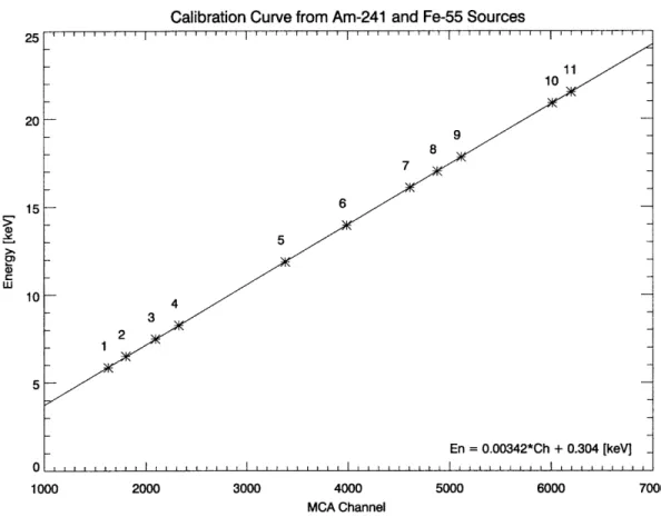
3.1 MCA Interface ... ... . ... 50 3.1.1 MCA Settings .. ... . 51 4 PHA Measurements 53 4.1 Energy Calibrations .. ... ... . 53 4.2 Plasma Measurements .. .... . ... . 56 4.3 Conclusion ... ... . 56
Chapter 1
Introduction
Creating new and alternative energy sources to meet the ever-growing global demand is one of the most difficult problems facing scientists and engineers today. Ever since crude coal fired power plants blackened 19th century cities, new technologies have emerged that have made electricity production cleaner and more efficient. Never-theless, it seems that power production through conventional fossil fuel based tech-nologies will never be sustainable. Creating power through nuclear fusion holds the promise of yielding a clean and nearly inexhaustible source of power through manip-ulating the same reactions that sustain the sun. Realizing this goal is not without challenge as scientists all over the world have strived to create energy through fusion for over fifty years.
The technique of magnetic confinement fusion studied in the Alcator C-Mod ex-periment holds the best chance of realizing net power production. This paper details the development of a new soft x-ray diagnostic in C-Mod to study the behavior of electrons and impurity ions in the plasma. The overall goal is to utilize advances in computerized signal processing elements to give researchers a between shot measure-ment of the emissivity of the plasma in the energy range of 1 to 30 keV.
The first chapter gives some background to the development and implications of nuclear fusion power. It then goes on to describe the operating goals of the PHA. The second chapter gives a theoretical model of the emissivity of the plasma in the soft x-ray range and considers the appropriate approximations based on the
limi-tations of the detector. The third chapter presents the PHA hardware along with calibrations and limitations of the system. Chapter four gives some sample spectra collected from plasma discharges and presents a comparision to the results from es-tablished diagnostics. Finally, possibilities for future expansions of the PHA system are discussed.
1.1
Background to Fusion Energy
While modern fossil fuel power plants are orders of magnitude cleaner than their predecessors, the finite fossil fuel supply and the environmental impact from these power stations calls into question the long term viability of energy from these sources. The majority of power production in the United States comes from coal, widely regarded as one of the dirtiest ways to generate power. Particulates, sulfur com-pounds, and heavy metals emitted from coal power plants are difficult to mitigate. Scrubbers can cut this pollution, but they add to the overall cost and complexity of the power stations. While government regulations can force operators to install these systems in the United States, countries in the developing world often lack this technology or incentives to install it. In particular, China, which is undertaking a massive expansion of their electrical production capacity through building new coal power plants, is set to overtake the United States in net carbon dioxide output.
The current alternatives to fossil fuels all have their own drawbacks as well. While producing little carbon, the massive Three Gorges Dam under construction on the Yangtze in China has displaced over a million people from their homes and drasti-cally altered the local ecology. Solar and wind power still cannot compete with the economies of scale possible through fossil fuels. Public opposition to nuclear fission power and concerns about proliferation have greatly curtailed the scale of nuclear power production. In comparison to other methods of generating power, nuclear fu-sion presents somewhat of an anomaly - power without appreciable carbon emissions and a fuel as common as water.
The chemical reactions in fossil fuel plants release energy on the scale of a few eV per reaction. Fusion reactions typically release energy seven orders of magnitude greater. Harnessing this energy source could revolutionize the way our society treats issues of development and economic leverage.
With the construction of the next generation ITER experiment expected to begin in 2008, research in fusion is on the verge of a great breakthrough in capabilities. Barring any major catastrophes, the knowledge gained at ITER should put researchers within striking range of building the first demonstration fusion power plant.
1.2
Progress in Fusion Research
With the advances of quantum mechanics in the early 20th century, physicists were first able to describe accurately the reactions that powered the sun. Beginning in 1920, Arthur Eddington advanced the idea that nuclear reactions, not chemical processes or gravitational contraction, were responsible for the great energy source within the sun. In the late 1930, Hans Bethe worked out the details of stellar nucleosynthesis and showed that the CNO cycle and p-p chain were the mechanisms by which hydrogen in the sun's core was converted into helium.
The next great advance in early fusion research came with the development of the thermonuclear bomb. Edward Teller and Stanislaw Ulam were the chief contributers to the design of a bomb which would produce the first artificial fusion reactions. The 1951 Teller-Ulam design became the basis of future thermonuclear weapons. While fusion can be produced with relative ease through detonating a thermonuclear weapon, creating and maintaining the extreme temperatures and densities necessary to produce fusion reactions are very difficult to do in a controlled manner.
The earliest efforts at creating a controlled nuclear fusion reaction centered on toroidal devices using electric currents to generate magnetic fields. Pinch devices dominated early research, but the inherent instabilities of these configurations pre-sented a major hurdle to progress. These early efforts were also constrained by the reality of the Cold War. Fusion power research was kept under close secrecy as it was
Figure 1-1: Cutaway of ITER device (published with permission of ITER)
largely a derivative of weapons research and itself a strategic asset.
Starting in 1958, the secrecy behind fusion research was lifted and a global effort towards realizing controlled nuclear fusion began to form. In 1968, Andrei Sakharov and his team unveiled the T-3 fusion experiment to the world. The novel device was based on a tokamak and had operating parameters far and above any other experiment in the world. Mainstream fusion research embraced the tokamak and construction of large tokamak-based fusion experiments began around the world in the 1970s.
In 1975, the Alcator A experiment began operation in the MIT Francis Bitter Magnet Laboratory. The experiment was conceived as a compact, high-field torus able to probe plasmas at densities and temperatures out of the reach of the reach of larger experiments. The facility was upgraded and in 1982 Alcator C went online. Finally, the latest iteration, Alcator C-Mod began operation in 1993.
In 1985, the European Union, United States, Soviet Union, and Japan agreed to collaborate on the construction of a next-generation fusion experiment. The exper-iment, dubbed ITER, underwent various political and financial difficulties over the next two decades owing to the diversity of the parties involved. The plan was final-ized in November 2006 with construction to begin in 2008 and generation of the first
plasma around 2016.
1.3
The Magnetic Confinement Solution
The problem in designing a containment vessel for a fusing plasma comes from the ex-treme operating parameters demanded of the device. For typical fusion experiments, the containment vessels have to contain plasmas with temperatures in excess of 10 million degrees. Fortunately, plasmas lend themselves to be contained by electromag-netic forces by nature of the charges of the constituents.
The early pinch devices use a single magnetic field to confine the plasma. Powerful magnetic coils lining the chamber generate a toroidal field that pinches and guides the plasma around the torus. The critical instability in a pinch device comes from a cross drift. Inhomogeneities in the applied magnetic field and centrifugal forces act on the plasma. As the plasma particles circulate around the torus, positively charged ions will tend to drift towards the top of the device and electrons will collect on the bottom.
These instabilities can be compensated for by applying an additional magnetic field. In tokamaks, a current is introduced within the circulating plasma. This current generates an additional poloidal field. The toroidal and poloidal fields superimpose to generate a combined field that traps the plasma along helical field lines wrapping around the torus.
Since the 1970s, tokamaks have been the mainstream of research into magnetically confined fusion. Consequently the physics of tokamak confined plasmas is better understood than any other configuration. With the exception of major breakthroughs in other devices, tokamaks have the best chance of achieving power production in the near future.
1.4
Nuclear Fusion Reactions
In the simplest terms, a nuclear fusion interaction occurs when two light nuclei com-bine to form a heavier daughter nucleus. For this interaction to occur, the two nuclei must have sufficient initial kinetic energies to overcome the Coulombic force of repul-sion from their positively charged protons.
If the nuclei can overcome the Coulombic energy barrier and come to a very close proximity, the nuclear force will dominate and pull the nuclei together forming a new atom. For light elements, the resulting atom will be in a lower energy state and thus some of the initial nuclear binding energy will be released in the form of energetic particles and photons.
Since the Coulombic repulsion is proportional to Z2 and the strength of the nuclear forces increases with the number of nucleons, the isotopes of hydrogen are an ideal fuel for fusion reactions. Because of the low temperature and high cross section for interaction, currently the most promising fusion reaction for study is that between the two hydrogen isotopes deuterium and tritium.
3T +2 D __4 He + n
The D-T reaction produces 17.6 MeV of energy in the form of the kinetic energies of the alpha particle and neutron. While the alpha particle can be contained using electromagnetic fields, the neutron escapes the fusing plasma taking a fraction of the reaction energy with it.
For a fusing plasma to be self-sustaining, the self-heating from collisions with the energetic alphas must compensate for the energy losses from radiation, interactions with the containment vessel, and other losses. A plasma at this state is said to be ignited, no additional heating is necessary to sustain the reaction. Producing ignited plasmas is one of the end goals of fusion research as power can be produced in the steady state.
1.5
X-Ray Emissions
Critical to constructing a successful fusion experiment is understanding and managing the power radiated from plasmas by high-energy photons. If we model the plasma as a black body, the peak in intensity will come from soft x-rays. Measuring this emission can yield information on the temperature and composition of the plasma.
The PHA diagnostic I have developed uses a high-range, low-resolution solid state detector to measure the soft x-ray spectrum from plasmas in C-Mod. While the Si(Li) detector used in the PHA system lacks the fine resolution of diffractometers, the modest resolution allows the detector to monitor emission over a large energy range.
PHA systems using solid-state detectors are nothing new to the Alcator exper-iment. Some of the first work with PHA systems in Alcator was done by Rice et. al.on Alcator A [1] and later on Alcator C [2]. Similar system are in use at JET [3], HT-7 [4], and nearly every other tokamak experiment.
The strength of the current PHA system lies in the use of modern computerized signal processing equipment, particularly the FastComtec MCA-3 multichannel an-alyzer, paired with a software interface developed to automate data acquisition and analysis. The new PHA system is a diagnostic that trades energy resolution for range to give an overall description of soft x-ray radiation from plasma discharges. Fast signal processing allows the PHA to operate continuously in real time across entire plasma discharges.
1.5.1
Measurement Goals
The PHA system has two overall goal from measurements of the emissions in the soft
x-ray spectrum from 1 - 30 keV.
The first goal is to measure bremsstrahlung radiation from the interaction of free electrons and ions in the plasma. Analysis of the bremsstrahlung spectra will give a measure of the thermal electron temperature. This measurement will act as a comparison to the values from established temperature measurements from electron
cyclotron radiation and Thomson scattering.
The second primary goal is to investigate the soft x-ray spectra from bound elec-trons in ionized impurities within the plasma. While the resolution of the detector is not sufficient to resolve the charge states of individual emitters, it will permit easy identification of impurity species over a broad range of energies.
Time integration of the data collection will allow determination of when the plasma takes on each impurity. Comparing these values to the measured electron temperature across different plasmas will yield information on the temperature dependence of the relative impurity emission rates.
The full spectrum from each discharge will give a measure of the relative abun-dance of impurity species relative to baseline values. For a variety of different plasma operating regimes a comparison will be done of the recorded impurity content and electron temperature.
An additional goal comes in the detection of plasma collision with the containment vessel. This will manifest itself as a sudden increase in the line strength of impurities that make up the plasma facing components. The PHA system will support the detection of these collisions.
Chapter 2
Soft X-Ray Emission
A theoretical description of the emission of soft x-rays in the 1-30 keV range can be broken into three broad categories depending on the final and initial states of the electrons. Free-free and free-bound electron radiation make up a radiation continuum while bound-bound transitions manifest themselves as discrete line emissions. The continuum radiation and line emissions will be treated seperately.
2.1
Continuum Electron Radiation
At temperatures above a few eV, the deuterium fuel inside the containment vessels is ionized. As we go higher in temperature towards the few keV in C-Mod, impurities within the plasma will ionize as well. We may divide the constituents of the plasma into a few broad categories. The main component of the plasma is the ionized deu-terium fuel. This ionization gives rise to two majority populations, the deudeu-terium nuclei and a collection of free electrons. In addition to the deuterium, there is also a very small population of alpha particles from fusion reactions.
Understanding the behavior of electrons in the plasma is of key importance to a successful fusion experiment. In particular, we may measure the interactions of free electrons with impurities to yield information about the plasma. Radiative free elec-tron interactions with impurities occur through two primary methods. An incoming electron may collide and scatter off an ion, emitting a photon in the process. This
free-free electron interaction is known as bremsstrahlung radiation. Similarly, an ini-tially free electron may collide with an impurity and enter into a bound state. The radiation emitted from free-bound interactions of this type is called recombination radiation.
For the range of x-ray energies visible through the detector, the bremsstrahlung and recombination radiation will come from a population of thermal electrons. The intensity of the bremsstrahlung spectrum will be dependent on the electron temper-ature. The overall goal from the measurement of free-electron radiation will be to arrive at a value for the electron temperature.
2.1.1
Bremsstrahlung Radiation
When a free electron collides and scatters off a positively charged ion, the electron will undergo a deflection from its initial course. In the deflection the electron ex-periences an acceleration. That acceleration causes the electron to emit radiation. This characteristic bremsstrahlung radiation forms a continuum with the energy of the emitted photon dependent on the initial energy of the electron, impact parameter of the collision, and the charge of the ion
For a first approximation, we may treat the problem classically as a two body col-lision. We have an electron with impact parameter b and initial velocity v0 scattering off the Coloumbic potential of an ion of mass M and charge +Ze. Two unbound orbits are possible, a parabolic orbit and a hyperbolic orbit. The path of the electron is described by the orbit equation as
41reomevdb2
r(e) = Z 1co+ O) (2.1)
Ze2 (1
+
E COS 0)where e is the eccentricity given as
47rEomv2b
E
and conservation of energy yields the relation
MV2 = Mý2 +(ý)2 Ze2
1/2mv = 1/2m
2+
1/2mr()
2(2.2)
47Eor"
Taking the interaction as a two body system suggests we use the dipole radiation formula to get the radiated power. If we calculate the acceleration of the electron from the orbit equation, we may then easily arrive at the dipole radiation spectrum [5]. dE 4 e2 d - d21 (w)12, (2.3) dw/2r 3c3 4reo e Ze me
M'
Here d is the non-dimensional strength of the electric dipole and /t is the reduced mass of the electron-ion system.
Following [6], we can express if(w) as a Fourier transform of the acceleration if(t) of the electron as described in our expressions for energy conservation and the orbit equation. Solving the differential equation for r given in 2.2 using 2.1 and differen-tiating yields an expression for if(t). Performing the Fourier transform on f(t) and substituting this expression into (2.3) gives the following
dE
4
e
22
d
=
-d2
J
(t)etdt
,(2.4)
du 3c3 47reo -0
Finally, to find the total power emitted per unit frequency per volume for an electron to interact with a collection of ions of density ni, we must multiply the above expres-sion by nivj. Integrating over all values of the impact parameter gives the following expression for the power spectrum
dP _ 4nivo e2 d2 2wbdb f(t)ewtdt (2.5)
dv
c3 47EO]o
]
t
Evaluating these integrals gives a formula for the classical bremsstrahlung energy spectrum which was first derived by Kramers [7]. In terms of Hankel functions of the
first kind, the full expression for the bremsstrahlung radiated power is dP 2Z 2ir2nid2 e2 )3
d- = 3cVo o iH (zvo)IH (w2o) (2.6)
dv
3c3vo
47rco
V2O
e
2
Vo0 = WCo ,
001
where vo is a non-dimensionalized frequency. This result can be expressed for the case of an electron scattering off a stationary ion in somewhat simpler form as [6]
dP 327r2Z2ni (_e2 3 7r/ uH ))
- = 2 -3iTn - U90oHu9o(U9o)H u9o(U9o) , (2.7) dv 3 em c3vo 4wco / 4
iwb9o b9o Ze2
U90 --" O , 4bom 2 (2.8)
vo
4ercomevowith boo as the impact parameter necessary for 90' scattering and ugo defined anal-ogously to vo. Grouping the Hankel functions together with u into a new function G(u) defined as G(u) = 43 Hu(u)Hu(u) (2.9) we can rewrite 2.7 as dP 327r2Z2 ni(e 2 3 d-v 3/mcv - G(u90o), (2.10)
dv
3
e
c3vo
(47rEO)
The non-dimensional factor G(u) is called the Gaunt factor after the work of J.A. Gaunt [8]. Gaunt originally derived approximation functions to G(u) as corrections to Kramer's derivation of the bremsstrahlung power spectrum to fit observations of astronomical x-rays. However, Gaunt was unable to devise a correction that gave a full agreement between Kramer's classical derivation and observations of high-energy radiation. To arrive at a full description of bremsstrahlung radiation, we must intro-duce quantumn mechanical corrections. These corrections are traditionally expressed as modifications to the Gaunt factor to preserve the classical limit of Kramer's deriva-tion.
Quantum Mechanical Bremsstrahlung
The first full quantum treatment of bremsstrahlung radiation was performed by Som-merfeld and Maue in 1935 [9]. The derivation was based on two quantum numbers, 70
and 7f, representing the initial and final energy states of the free electron in a manner analogous to the energy states of bound electrons in the Bohr model. We may define these quantum numbers in terms of the ionization energy of hydrogen RY = -13.59 eV and the frequency of the emitted radiation v as
Z2 R Y 1 2 Z2 = Eo = = -m•mv, (2.11)
710
2
1 1 hv = Z2RY( - 1 (2.12) rif 77iThe quantum mechanical Gaunt factor was given in 1939 by Sommerfeld[10] in the form
G= 2 1(_ e2|,1
d
IF (x) 2(2.13)
(e~w7 - 1)(I - 2Tf)d
where F(x) is the ordinary hypergeometric function defined as
F(x) =2 Fi(Mro, Zqf; 1; -x) (2.14) 2 = 1+ lo X + (Zl 0 -_ T12) (Z /f T12) -+ ..., _ 4 770'tlf
(m;
- 0)
2
To calculate the emissivity of the bremsstrahlung radiation, we return to our expression for the differential power spectrum 2.10 and integrate over an appropriate electron energy distribution. The emissivity comes from evaluating the integral
47r(v)) =
/dP
f(v)d vf
(2.15)Here the emissivity is in units of power
/
unit frequency volume solid angle. Con-tinuum radiation in the soft x-ray range in Alcator has been observed fromelec-tron bremsstrahlung radiation[I]. Taking the elecelec-tron energies to follow a Maxwell-Boltzmann distribution and integrating over the initial electron velocity v0 we have
JO) 2 mG G(',VO)emv/2kT4 vd (2.16)
47rc() = A 2 GT Voo 2kT4X dvo
(2.16)
32w2Z2ri (_ 2 3
A
= 3v 2Z2 °4
) (2.17).F30m2c vo 47co
Where I have grouped all the constants into a factor A with units of power per unit frequency. Rewriting the integral in terms of Eo0 = 1/2mvy yields [6]
()
= ne G(v, v)e-Eo/kTdEo (2.18)c(v,) = 27r& 2rkTJ, kT
(2.19)
Using 2.11 and 2.12, we may rewrite the integral in the above expression in terms of of the final electron energy
-h/k oGc • , hi,')e-Ef/kT dE f
gff = e-hu/k T G(v, Ef + v)e-E kT (2.20)
This quantity gff is called the Gaunt factor for free-free emission. This represents the quantum mechanical correction for free-free electron interactions. Rewriting the total bremsstrahlung power per unit frequency given in 2.16 in terms of this new factor, we have
8irZ2 rue e2 m -h/T
E(V)
= 8rcZ2nin( C2 ) m -he v/kTgff (2.21)3
v/ 2C
m
3
4-FEO
2xkTe
This expression gives the total bremsstrahlung power emitted from thermal electrons in a Maxwellian plasma interacting with a single impurity species in terms of the ion and electron densities, the plasma temperature, and the Gaunt factor for free-free emission.
Even though we have an expression for the intensity of the emitted radiation in closed form in 2.21, the presence of the hypergeometric function in gff makes this expression difficult to use in practice. Fortunately, we can use an approximation in
place of the free-free Gaunt factor. For the range of x-ray energies likely to be seen by the detector, replacing gff by (hv/kT)3 gives a very good approximation [1].
Observation of the bremsstrahlung spectrum from plasmas yields a continuum spectrum with discontinuities which our formula for continuum radiation cannot ex-plain. A correction for recombination radiation is needed to introduce the quantized nature of the bound electron energy levels in the impurity ions.
2.1.2
Radiative Recombination
Radiative recombination is the process by which an initially free electron is captured and put into a bound state by an impurity ion. Recombination radiation was first discussed by Kramers [7] then Menzel and Pekeris[11] and expanded by Brussard and Van de Hulst[12] and then Karzas and Latter[13]. Here I present an overview of the calculation of the power spectrum from radiative recombination.
We can understand free-bound electron transitions in terms of transitions from free hyperbolic orbits into bound elliptical ones. The process releases an energy which can be expressed as
1 1
AE
2 2(2.22)
where n is the principle quantum number of the final bound state and ro is the Sommerfeld quantum number for the free electron. The electron interaction with the atom is dependent on the initial electron energy. For an electron with initial kinetic energy Eo = 1/2mvy, recombination is only possible if the initial energy is less than the energy of the bound state, E0 < Z2R
n2. If the opposite is true, the electron will scatter off the ion and emit bremsstrahlung radiation.
For the case of electron recombination, we can rearrange 2.22 to give the allowed energy spectrum.
Z2R
AE=
+
Eo
(2.23)
or, rewriting to give the radiation spectrum, we have
Z2 Ry
hv -Z2 + 1/2myv, (2.24)
The radiation spectrum will thus be a series of discrete jumps superimposed on the bremsstrahlung continuum.
Following [6], we may arrive at a semi-classical estimate of the recombination radiation by the correspondence principle. Assuming a parabolic collision, the radia-tion spectrum from recombinaradia-tion should come completely from quantized radiaradia-tion. There will be no continuum, only a series of stepwise radiation bands. However, the correspondence principle tells us that at the limit of high electron energy any formula we derive for recombination radiation should reproduce the bremsstrahlung continuum. Using this reasoning, each recombination level n should quantize the bremsstrahlung continuum for some region near n. We can modify our expression for the radiation spectrum to account for this by quantizing the bremsstrahlung contin-uum using 2.24.
Around each level we take the condition that each discrete energy level covers some range in the continuum. The recombination energy hu quantized by the nth level is smeared out over a range given as
2 Z2R hv2
1/2mv2
< hv <
1/2mv
2Z
1
(2.25)
(n + 1/2)2 + (n - 1/2)2'
The power emitted from the capture of an initially free electron into a bound state n is then
P(n) = dP Vgn(V), (2.26)
du
where we use the expression given in 2.21 for d in the classical limit. dP 32w2Z2ri ( 3
d = A = 3v2_mcv ° ) (2.27)
du 30 c3 4eo24
The quantum mechanical calculations are encapsulated in the new Gaunt factor g,(v). Calculations of this factor are similar to that of the free-free Gaunt factors and amount to evaluating transition dipole matrix elements with final states that are bound. Low-Z impurities present in the plasma, like carbon and oxygen, are likely to be completely ionized. For low-Z impurities, calculations of the transition dipole matrix elements are straightforward and the recombination radiation can be easily calculated. Calculations of the Gaunt factor for partially ionized heavy impurities are considerably more complex. In many cases it is easier to measure directly the radiation spectrum from partially-ionized heavy-Z impurities than calculate the emitted power from 2.26.
Using 2.25, the frequency range quantized by each level Av, is approximately
A =2Z2R
v = 2Z2R (2.28)
hn3
Substituting the expressions for Av. and dP into 2.26 gives
P(n, vo) = Ag(v) hn (2.29)
This is the power emitted from recombination radiation of an electron with initial velocity v to the energy level n. To calculate the total power emitted from an as-sembly of electrons, we must convolve the power spectrum with the electron energy distribution and integrate over the electron velocity. However, since the recombina-tion radiarecombina-tion is quantized by n and lacks a continuum to sum over, we can write the recombination radiation contribution simply as
41rE(v) = Pn4v 2 d v dv', (2.30)
Rearranging our expression for the radiation spectrum gives an alternate form for the electron velocity in terms of the emitted photon energy and energy level of the final
bound state.
2
Z
v = -(hv- ) (2.31)
m n
Substituting this back into 2.30, the emissivity of the recombination radiation is then e(v) = nA m e [2Z2 gn(h)eZR/nkT , (2.32)
4---Tn[k•e-- gL vjn3
2.1.3
Combined Bremsstrahlung and Recombination
Radia-tion Emissivity
Comparing the emissivities from recombination and bremsstrahlung radiation, the two emissivities have the same physical dependences. We can then set them equal up to a constant [14].
e(')recomb = 6(V)brems(7 - 1)
(2.33)
here the quantity (-y - 1) is equal to the term in square brackets in 2.32. Since the
total intensity of the continuum is I = I•brems + Irecomb, the factor 7y describes what
portion of the continuum comes from recombination radiation. This term is called the x-ray enhancement factor and its behavior explains the finite steps in the continuum from recombination radiation. As shown in 2-1, the continuum exhibits a series of edges. Since there is a minimum photon energy from recombination corresponding to an incoming electron at rest, the recombination radiation will exhibit a series of steps at energies defined as the recombination edges. For increasing temperatures, "7 grows smaller as more electrons are ejected from bound states in ions and the contribution from bremsstrahlung grows greater. Comparing the recombination radiation inten-sity to our previous expression for the bremsstrahlung inteninten-sity, we can express the combined emissivity of the power radiated from bremsstrahlung and recombination
IV I0' "o 10 s:C Ni t series l imits 9T0 18.0 Z7.0 36.0 x10O V (s-')
Figure 2-1: Combined bremsstrahlung and recombination radiation spectrum from carbon (after [15])
as
A
m hi 2Z2RY 2VnkE(4)
=
n,
gk
+
kT-
3
gn (v)
eZ
2~ 2kT
(2.34)
Radiative recombination varies more strongly with atomic charge than bremsstrahlung. For recombination radiation, we have e oc Z4 while bremsstrahlung power varies only as Z2. This result agrees with our conceptual picture of recombination radiation; higher-Z impurities should more strongly attract electrons into bound states and thus recombination radiation should be stronger in Z than bremsstrahlung.We can write the combined bremsstrahlung and recombination radiation in terms of a modification of the gaunt factor. The new combined gaunt factor is then [1]
g = g f + f,(T, hv) (2.35) 0i/n2 f (T,hv) )=20 n0 gn(v), (2.36) n=mi (hu) Z2j~ O - ZkT2 (2.37)
The expression is summed from the lowest quantum number n = mi(hv) which corre-sponds to the lowest energy level the electron can be bound to and still emit a photon of energy hv. We define this level as
mi(hv) - 1 < h )1/2 < mi(v) (2.38)
Z2RY),<
i
The exponential factor 9i in the expression for
fi
(T, hv) determines the relative strength of the contribution from recombination radiation. For a typical electron temperature of a few keV, the contribution from recombination with the major con-stituents of the plasma (deuterium and helium) is negligible as 0i 10- 3. However, for impurities with Z > 10 we have 0 greater than 1 and recombination radiation becomes a major contributer to the plasma radiation continuum.Finally, summing over all impurity species gives the total emissivity from free electron interactions.
8ii-Z2 n2 / 2 \ 3
e(u) = 8 ef
(
e m e-hv/kT (gfIf + fi) (2.39)3V/3M2
\
4ircoJ
2irkTe(39
Zeff -= n-Z2 (2.40)
ne
where we define an effective charge Zeff that is characteristic of the entire plasma.
2.1.4
Profile Effects
With the expression for the combined bremsstrahlung and recombination emissivity, we may calculate the total photon flux incident upon the detector. Emissivity is defined as power per unit frequency volume solid angle. The differential form is
dP
de(u) - dVdQd= (2.41)
We know that the detector subtends a solid angle AQ. Multiplying through by 'Q gives
AQde(v) = dP(242)
h dVd(hv) (2.42)
The incident power comes through a flux of N photons per second, each with an energy of h'. Substituting in dP = hvdN/dT we have
AG
AQ()
hv dN/dt= h) dNdt (2.43)
h d(hv) dV
To simplify the problem, we may assume that the plasma cross section is circular. Since the detector views the plasma through a chord of cross section dA, we can replace the volume element with dV = dAdl. Here 1 is the length of the chord that the detector sights along. The variable 1 is related to the toroidal parameter r by
12 = r2 - d2
where d is the distance from the chord to the center of the torus. The above relation becomes
AtcvdAQ()dl - hv dN/dt
h dNdt (2.44)
h d(hv) dA
The left hand side is the differential photon flux incident upon the detector from a region of the plasma of thickness dl and cross sectional area dA. If we integrate over
1, the total photon flux in units of photons /(second cm2) is
I(v) = Ah e(v)dl (2.45)
Following [1], we may calculate the incident photon flux by taking representative func-tions for the parameters in 2.45 and performing the integration. Taking a parabolic density profile, we may write nfe(l) as
T2
12
+
d
2
ne(1) = no(1 - ) = n0(1 - 2+ ) (2.46)
where no is the central plasma electron density and at is the limiter radius. The temperature profile is assumed to be Gaussian and vary as
T(1) = Toe-r2 2 Toe(_ 2+d)/a2 (2.47)
where a is the characteristic width of the temperature profile.
For a clean, hydrogenic plasma we have Zef = 1 and n (1) = ne(1). Using the
approximation gff(1) = (hv/kT(1))'/ 3 and assuming that recombination radiation is negligible for a hydrogenic plasma, 2.45 takes the form
AA- m -IL hv )
I(V) = n e(1)2 e kT( kl ) (2.48)
4x h 0
V27kT (1)
kT (1)
Inserting the functions gives
1
AAQ• 2 m hv •L L 2
5(d
2+ d
12+
d24
h
-n 2rkTokTo
)expC5(/ 2±d
2)() = o T a• )exp 6a2
+
exp( 2 2 ))dlThe integration contains terms only dependent on the geometry of the detector and will be constant between shots. Since the PHA is only concerned with the relative itensities of the emission, we may absorb the integration into a constant. Dropping all terms that are constant between shots yields an expression for the relative photon flux incident upon the detector face
1
(V) oc Z2 2 1 hv • -hv
I(n)
oc Zo
kokT To
exp(-
k
To
)
(2.49)
2.1.5
Temperature Measurement
By measuring the relative bremsstrahlung intensity we can easily come to the central electron temperature. Taking the logarithm of 2.49 gives
hzv 1 hv 1
where I have lumped together all the constants into the factor Io. For temperatures above RY = 13.59eV and hv > kT the term v dominates the spectrum.
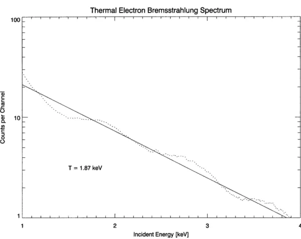
A semi-log plot of the intensity of the bremsstrahlung radiation against the energy of the detected x-rays will give a straight line with the slope inversely proportional to the electron temperature. Measurement of the bremsstrahlung spectrum will then be our primary method of determining the central electron temperature. This measure-ment is somewhat complicated by the presence of recombination radiation which will in practice be measured alongside the thermal bremsstrahlung. As shown for carbon in 2-1, the discontinuous recombination edges will distort the thermal bremsstrahlung continuum and must be cut out during analysis.
2.1.6
Bound Electron Interactions
In addition to the free-free and free-bound electron interactions that are responsible for the thermal continuum, electrons may transition between bound energy states. The simplest case for line radiation is a hydrogenic atom. We may quantize the electron energy levels using the Bohr model.
E= Z P (2.51)
i n2
An electron transition between two levels, nj and n2, will then give emit a photon with wavelength given by the Rydberg formula
he
1 1
= 2- (n2 n2) (2.52)
Using this formula, we can make a first approximation to the range of impurities species viewable by the detector. The energy range of the detector is from about 1 keV up to 30 keV. The strongest line radiation should come from K-alpha emission due to electron transitions from the innermost K shell to the second L shell. We can make the approximation that the remaining electron in the K shell will screen the nuclear charge giving an effective charge of (Z - 1). Using the Rydberg formula,
an energy range of 1-30keV corresponds to K-alpha radiation from elements with 10 < Z < 55. Many constituents of the the plasma facing components fall into that range. Line radiation is expected from A1, S, C1, As, Ti, Cr, Fe, Ni, Cu and Mo.
Radiative Transitions and the Einstein Coefficients
We may describe the emission of photons from bound electron transitions in terms of the Einstein coefficients. For simplicity, consider a collection of a single impurity species with two bound electron states. The lower state has a wave function
101
> and the upper state is 102 >. The total impurity density is ni with nl of the atoms in the lower state and n2 in the upper energy state.There are three different processes by which an electron may transition between the two states. An electron initially in the upper state may spontaneously decay into the lower state and emit a photon. If we assign this process a rate coefficient A2 1,
the total rate of spontaneous decay is given as n2A21. Similarly, an electron in the
lower state may absorb a photon and be promoted to the higher state. The transition rate for this process is described by another coefficient B12I(u) where I(u) is the energy density of the electric field of the absorbed photon. The upward transition rate is then njB12I(v) Finally, an electron in the upper state may absorb a photon and undergo stimulated emission. The rate coefficient for this process is B21I(u) and the downward transition rate is n2B21I(V).
For the atoms to be in thermal equilibrium, the total upward transition rate must be balanced by the downward rate of transitions. We can write this balance as
n2A2 1 + n2B21I(V) = n1B12I(u) (2.53)
Denoting the energy of the two states as El and E2, a downward transition releases an energy
At a temperature T, the number ratio of the two states is then
ni1 = e(E1/kT) = ehvl2/kT (2.55)
n2 e- (E2/kT)
Solving the balance equation for I(v) gives
I() = A2 1 (2.56)
ehv12/kTB 12 - B2 1
At thermal equilibrium we may take the electromagnetic energy density to be given by the Planck radiation formula.
4hv3
I(v) = c3(eh/kT- 1) (2.57)
c3
(ehv/kT
Comparing these two expressions for I(v), we must have B12= B2 1 and A21 given as
8-xhv3
A21 - 3 B21B (2.58)
Using this rate coefficient, the emission coefficient for spontaneous emission from this single transition is
hv2 1
=(v21) 421 n2A21¢(v21),
(2.59)
41r
where ¢(v21 is the line emission profile. While atomic transitions have very well defined energies, the uncertainty principle and perturbations to the energy levels broaden the emission profiles away from delta functions. To calculate the emission coefficient from line radiation we will need an expression for the emission profile.
Emission Profiles
In the absence of broadening effects the profile from line emission would be sharply centered around the transition frequency. The emission profile would be very well described by a delta function. However, perturbations to the energy levels from
quantum effects, observation effects, and interactions with other atoms spread out the emission profile. The two main broadening effects are natural broadening from the uncertainty principle and Doppler broadening from the motion of the particles in the plasma. The electric fields from nearby particles tends to perturb the energy levels of the emitter through strak broadening. However, these effects are expected to be too small to measure with the PHA detector.
Natural Line Broadening
The mean lifetime of the excited state determines the natural width of the line emis-sion profile. The Einstein coefficients are defined in terms of transition probabilities expressed in transitions per unit time. It follows that the lifetime of the excited state
1'2 >is inversely proportional to the transition rate. 1
- A21 (2.60)
The uncertainty principle gives the relation between the lifetime of the excited state and the measurable spread in the energy of the line radiation.
AE = (2.61)
At
The natural width of the line emission profile will then be
1
Av- 2= At
27rAt
(2.62)For the electrons in the excited state, the decay to the ground level is described in terms of an exponential function
n2(t) = n2(O)e- ' / At (2.63)
so that the fraction of atoms in the excited state at time t is given as e-t/r. Performing a Fourier transform on this quantity yields the fraction of ions in the excited state as
a function of the frequency.
2 f
f(V)
= e-t/Ate-2ivtdt (2.64)(o=v:
Evaluating this integral gives the familiar Lorentzian distribution centered around the spontaneous transmission at vK
1 1/2irAt
f
() =
7r (1/2wAt)
/2 t
2+ (V)2
(2.65)
where f(v) is normalized so that f ". f(v)dv = 1. Finally, convolving the fractional
distribution of the energy states with the delta function model of the line emission gives the line emission profile due to natural broadening.
1 Av
(v) = - (2.66)
7r (Av)2 + (V - V21)2 .66)
Doppler Broadening
In addition to the natural broadening from the uncertainty in the energy, a broadening is introduced from the Doppler shift caused by the motion of the particles in the plasma. For non-relativistic motion, the Doppler shift in the frequency v21 due to the particle velocity v along the line of sight of the detector is
A V =v21
AV = V c21 , (2.67)
C
For the thermal particles in the plasma, the velocity distribution will be Maxwellian. The fraction of atoms with velocity in the range v to v + dv with respect to the detector is then
m -my 2
f
(v)dv= exp(( 2 )dv, (2.68)where m is the mass of the emitter ion at temperature T. Writing Av = v21 - v and
solving for v in 2.67 gives the particle velocity in terms of the shifted frequency.
v = (1 - ) c (2.69)
/21
Finally, substituting the above expression into 2.68 and convolving with the initial assumption of a delta function emission profile gives the Doppler broadened line emission profile in terms of frequencies. The distribution is thus a Gaussian centered at the transition frequency v2 1
m
xp(mc2 (V21- 2¢b(u) =
( 2 7rkT
expkTkT
2z ) (2.70)2v221
For hydrogenlike argon at 3.7 A, the lifetime of the excited state has been measured as 3.54 x 10- 9 s [16]. The line broadening from the uncertainty principle is on the order of 10-6 eV and negligible to the PHA.
Ion Temperature Measurement
Measurements of line radiation will encounter both Doppler and natural broadening. The combined effects of these broadening mechanisms will be to create a new emission profile. The convolution of the Lorentzian and Gaussian is a Voigt profile. Doppler broadening is expected to dominate over the natural line width. The measured line shape should. be approximately Gaussian.
We may arrive at an estimate of the ion temperatures by measuring the FWHM of the Doppler broadened energy distributions. The FWHM of the Doppler energy distribution is given as
hAV12 = 2V2 ln(2) ic hu21 (2.71)
olving for the temperature gives
kT= mC2 (hv
112)2 (2.72)
8 ln(2) (hv)2
For a typical ion temperature on the order of 1 keV and a transition energy of 10keV, the Doppler broadened width will be on the order of 1 eV. Unfortunately, the overall resolution of the detector is two orders of magnitude higher. Ion temperature diag-nostics have traditionally used crystal spectrometers [17]. While measuring Doppler shifts is out 'of reach for the current PHA system, future advances in detection equip-ment should make ion temperature measureequip-ment a goal for subsequent PHA systems.
Combined Line Emission Profile
As stated before, Doppler broadening is expected to dominate over the natural line width. However, the Doppler width is much smaller than the resolution of the detec-tor. Since the broadening is too small to be recorded by the detector, we may discount line broadening and treat the line emission profiles incident on the detector as delta functions. The main source of broadening will come within the detector itself. Thus the emissivity that the detector see will be simply
hi21
e(v 2 1) = rhivA21, (2.73)
47r
2.1.7
Impurity Line Radiation
If we assume the plasma is in coronal equilibrium, ions are promoted to excited states by collisions with free electrons and downward transitions occur through spontaneous emission. Here, I present the simpler case of collisional excitation. This occurs when a free electron collides with an ion and promotes a bound electron to a higher state. The excited bound electron then transitions downwards, emitting a characteristic photon. We can arrive at an estimate of the emissivity from collisional excitation by means of the Einstein coefficients.
Collisional Excitation
To calculate the emissivity of the line radiation we must first calculate the cross section for excitation. For monoenergetic electrons, a collection of ni ions in the
lower energy state sees an incoming flux of nev electrons. For an interaction cross section a12, the total reaction rate per unit volume is then
Ro = nevnl12 (2.74)
Extending this to a Maxwellian population of thermal electrons, we must take the velocity average of the reaction rate.
R =< Ro >= nenl al2v 2Uf(v)d3v, (2.75)
Here the lower limit of integration is the velocity v0 which corresponds to the incoming electron having just enough energy to excite the bound electron to the next state. The minimum velocity is defined as 1/2mv2 = hv
12.
With the line emission profile defined, we return to our expression for the emissiv-ity 2.73. For an optically thin plasma, downward transitions from stimulated emission can be taken as negligible. We can then rewrite the balance equation as
n2A21= nIB1 21(v) (2.76)
Since the collisional excitation rate is specified in 2.75, we can set R = nentB12I(v) or
A21 = ne Ji 2v
f (v)d3v
(2.77) n2At temperature T, the ratio of the density of ions in each state is
1_• _ep-E12
n= exp( ) (2.78)
For an opticly thin plasma with a single two-state ion, in terms of the interaction
cross section, the emissivity is
hv1 2 -hz 12 tc 1(v) = 4 neni exp( kT ) aU
12vf(v)d3v, (2.79)
47r
kT
fUO
Following [6], we can arrive at a semi-classical estimate of the collisional excitation cross section by approximating the electron-ion system as an electric dipole. For collisional excitation, we can treat the perturbing electric field of the colliding electron in very much the same way as we did for bremsstrahlung radiation. A collision between a free electron and an ion has a certain chance of inducing an electron transition that is related to the Einstein coefficient B12. The interaction cross section
is
1 2 =B 1 2
7r Rao
G (2.80)where a0 is the Bohr radius, v is the velocity of the incoming electron, and G is the
usual Gaunt factor which encapsulates the quantum mechanical corrections. Contin-uing our assumption of an electric dipole and dropping higher order contributions, the transition probability B12 can be written in terms of the dipole moment of the
system [18].
47rB
2 2e 2 r 12(2.81)
3coh2C
B12- =3WC I < '021 )l > (.1
here the quantity
I
<1
211I1> 12 is the the square of the magnitude of the dipole moment for the transition and 7 is the sum of the position vectors of the all of the interacting electrons.For hydrogenic ions, we can easily calculate the magnitude of the transition dipole moment. The heavier impurities in the plasma will only be partially ionized. Calcula-tions of the transition dipole moment must take into account the complex interacCalcula-tions between the transitioning electron and the rest of the bound electrons in the ion. In addition, screening effects must be included to account for the fact that each electron only sees a portion of the nuclear charge. The matrix elements for the transition dipole
moment for heavier ions are not well described analytically and must be measured empirically.
We can express the cross section given in 2.80 in terms of classical oscillators. We define the classical oscillator strength f12 as the ratio of the number of classical oscillators to the number of ions in the upper level. For states that are weak emitters, transitions occur infrequently and the ion can be treated as a state of relatively few oscillators so f12 --+ 0. Conversely, strong transitions oscillate more readily and so nearly all the electrons may be modeled as oscillators, f12 --+ 1. This ratio is given in terms of the Einstein coefficients as
4wEo me
f12 ro m h12B12 (2.82)
The oscillator strengths are generally well known from empirical measurement and are compiled by NIST. Using oscillator strengths in our calculations is advanta-geous because they are unit-less quantities. Unlike the Einstein coefficients, oscillator strengths merely describe the strength of the transition.
In terms of classical oscillators the cross section in 2.80 is then e2 R, R,~ flG
e122 Ry Ry f12 (2.83)
47rEa 2 o 1/2mev2 hv
12
v 3(
Which we can rewrite to recover the form originally given by van Regemorter [19] as
87 812 - R2 (hV12)
=( 1a 2 G(v) (2.84)
73=
1(hv12)2 1/2mev2The emission rate is then
647aoR3 m -h212 -mV2
R = f•2 kT exp kT) exp( 2kT)vG(v)dv (2.85)
limit. The integration yields
647r3 aRne m (m
R = 64 aO•ekTfl2 exp (282kT6)
hv12m 2.kT
2kT
The total emissivity is
M(v
1 2)
a
22 M:f2kTninT exp 2hV2 (2.87)
C(m2 M2
V2:rk:T
kT
Dropping the constants yields the overall temperature dependence of the emissivity
e(v12) c nif12 exp ( 2 kT h )
V
(2.88)For a given transition, the emissivity is exponential for low temperatures and goes as vT for kT > hV12.
The difficulty in measuring the throughput of the PHA system means that we cannot in general measure absolute emissivities. However, measurements of the line strength of each shot relative to a baseline will yield information on the relative im-purity concentration. For each shot, we may use the the temperature found from measuring the electron bremsstrahlung radiation to factor out the temperature de-pendence of the emissivity. With the complicating effects of temperature factored out, the relative ion density can be determined by the ratio of the measured line strength to the baseline value.
Chapter 3
Detection and Signal Processing
Apparatus
Alcator C-Mod is a compact, high field tokamak with a major radius of 68 cm and a minor radius of 22 cm. While the small size of C-Mod allows record high magnetic fields, the compactness makes ensuring all the diagnostics have a view of the plasma a rather difficult problem.
Ports on the outside of C-Mod allow for diagnostic access to the plasma. The soft x-ray PHA diagnostic views the plasma through K Port. The PHA viewing chord is nearly at the midpoint of the torus so the PHA sees a good portion of the central and edge effects. Since so many diagnostics are packed around the device, a long beam line was installed to carry the photons from the exit point at the K port flange to where there was space to fit the detector.
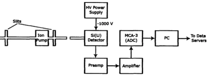
A block diagram of the experimental apparatus is given in Figure 3-1. The left most side indicates the connection to the K port flange. From the flange, a 2 3/4 inch stainless steel tube forms the beam line that carries the x-rays from the plasma. Approximately 65 inches along the beam line, a slit was installed to collimate the x-rays. From the pinhole aperture of the slit, the x-rays continue out another 60 inches until they encounter another collimating slit.
Since the beam line is in direct contact with the plasma, it is essential that the interior be held at vacuum. An ion pump was attached to ensure that the beam line

![Figure 2-1: Combined bremsstrahlung and recombination radiation spectrum from carbon (after [15])](https://thumb-eu.123doks.com/thumbv2/123doknet/13917805.449517/27.918.307.607.108.437/figure-combined-bremsstrahlung-recombination-radiation-spectrum-carbon.webp)
![Figure 3-2: ORTEC SLP Silicon (Li) X-Ray Detector in PopTop Capsule. Adapted from [20]](https://thumb-eu.123doks.com/thumbv2/123doknet/13917805.449517/45.918.258.677.112.392/figure-ortec-slp-silicon-detector-poptop-capsule-adapted.webp)
![Figure 3-3: Diagram of Si(Li) detector element. Adapted from [20]](https://thumb-eu.123doks.com/thumbv2/123doknet/13917805.449517/47.918.264.681.110.383/figure-diagram-si-li-detector-element-adapted.webp)
![Table 4.1: Reference transition energies Peak Emitter Transition Energy [keV]](https://thumb-eu.123doks.com/thumbv2/123doknet/13917805.449517/53.918.283.645.764.1055/table-reference-transition-energies-peak-emitter-transition-energy.webp)