HAL Id: in2p3-00802929
http://hal.in2p3.fr/in2p3-00802929
Submitted on 20 Mar 2013
HAL is a multi-disciplinary open access
archive for the deposit and dissemination of
sci-entific research documents, whether they are
pub-lished or not. The documents may come from
teaching and research institutions in France or
abroad, or from public or private research centers.
L’archive ouverte pluridisciplinaire HAL, est
destinée au dépôt et à la diffusion de documents
scientifiques de niveau recherche, publiés ou non,
émanant des établissements d’enseignement et de
recherche français ou étrangers, des laboratoires
publics ou privés.
SPIRAL2 RFQ design
R. Ferdinand, G. Congretel, A. Curtoni, O. Delferriere, A. France, D.
Leboeuf, J. Thinel, Jc. Toussaint, M. Di Giacomo
To cite this version:
R. Ferdinand, G. Congretel, A. Curtoni, O. Delferriere, A. France, et al.. SPIRAL2 RFQ design. 9th
European Particle Accelerator Conference (EPAC 2004), Jul 2004, Lucerne, Switzerland.
pp.2026-2028. �in2p3-00802929�
SPIRAL 2 RFQ DESIGN
R. Ferdinand
#, G. Congretel, A. Curtoni, O. Delferriere, A. France, D. Leboeuf, J. Thinel,
JC. Toussaint, CEA-Saclay, DSM/DAPNIA/SACM, 91191 GIF-Sur-Yvette, FRANCE
M. Di Giacomo, GANIL, Boulevard H. Becquerel, F - 14076 Caen
Abstract
The SPIRAL2 RFQ is designed to accelerate at 88MHz two kinds of charge-over-mass ratio, Q/A, particles. The proposed injector can accelerate a 5 mA deuteron beam (Q/A=1/2) or a 1 mA ion beam with Q/A=1/3 up to 0.75 MeV/A. It is a CW machine which has to show stable operation, provide the requested availability, have the minimum losses in order to minimize the activation and show the best performance/cost ratio. It will be a 4-vane RFQ type, with a mechanical assembly, the global goal being to build an RFQ without any brazing step. Extensive modelisation was made to ensure a good vane position under RF. A 1-m long hot model prototype is under construction in order to validate the manufacturing concept.
INTRODUCTION
The SPIRAL 2 extension of the existing GANIL facilities is under detailed study. It will extend the exotic particle productions of the present SPIRAL cyclotron towards heavier elements [1].
The first idea was to use a deuteron beam to induce fission in an uranium target. A specific driver was chosen, and the concept of a superconducting linear accelerator for very high intensity light and medium-heavy ion beams was selected as the best option. The acceleration of deuterons by this driver would achieve the specifications fixed for SPIRAL 2, namely 1013 fissions per second. The project is in the detailed study phase which has to be finished in October 2004.
The driver is required to accelerates in CW mode either 5 mA of deuteron beam up to 40 MeV or 1 mA of Q/A=1/3 particles to an energy of 14.5 MeV/u. It will be made of two dedicated ion sources, a single RFQ, and 2 families of superconducting quarterwave resonators. This paper describes the RFQ development.
DESCRIPTIONS
The SPIRAL 2 RFQ is a 5-m long cavity CW machine with the following specifications :
• Obtain the requested intensity and emittances
• Have a stable operation and a good reproducibility
• Show the requested availability
• Have the minimum losses in order to minimize the
activation
• Have the best possible performance/cost ratio.
Cavity types
The different cavity types were first evaluated. We were helped in this task with a comparison made for the RIA
project at MSU [2]. The power consumption of the most common RFQ structures was compared: split coaxial, four rods, IH, and four vanes. The comparison was performed for the same RFQ aperture (4.5 mm), vane voltage (60 kV) and frequency (80 MHz).
Figure 1 : Cavity types evaluated for the comparison. The analyses showed that 4-vane structures are the less consuming ones (more than a factor 2 compared to 4-rod or IH structures). 4-rod RFQs show a very high peak power loss (91.5 W/cm2). This value can be manageable (IPHI 352 MHz RFQ operates at a higher peak value), but it induces engineering difficulties and possible deformation in CW mode. Split coaxial RFQs look not far from 4-vane RFQs, if the opening is not too big.
The 4-vane structure is the oldest one and one of the most frequently built for RFQs. It has been used for CW operation at 80 MHz successfully [4]. 4-vane RFQs are well known in the CEA laboratory [5]. They have shown good reliability in CW condition [6]. Taking into account the above results and the availability and knowledge of the team, it was decided that the SPIRAL 2 RFQ would be a 4-vane RFQ. 0 0.2 0.4 0.6 0.8 1 1.2 1.4 1.6 0 50 100 150 200 250 300 350 400 450 500 550 Z (cm) Ap e rt u re s (c m ) , vo lt ag e ( x 10 0k V ), D + E n er g y ( M eV ) -90 -80 -70 -60 -50 -40 -30 -20 -10 P h ase ( d e g ree) Mean aperture R0 (cm) Min aperture a (cm) Vane voltages (100xkV) Deuteron energy Phase (deg)
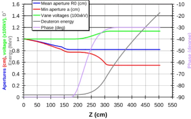
Figure 2 : Main parameters of the RFQ
Mechanics choices
The RFQ was designed by the SPIRAL 2 beam dynamics team in end-to-end linac simulations. The calculations [3] show beam transmission higher than 99%. With all combined errors it has to be higher than 97% in order to allow hands-on maintenance on the
Proceedings of EPAC 2004, Lucerne, Switzerland
cavity. The main parameters are described in Figure 2 and in the table below.
Parameter Value
Length 5.077m Mean aperture R0 8.1 – 10.0 mm Vane voltage 100 – 113 kV Modulation 1 – 1.99
Input rms emittance (π.mm.mrad) 0.2 (D+) / 0.4 (1/3) Transverse emittance growth 0
Peak electric field 1.65 kp Transmission w/o errors >99.9% Input energy 20 keV/u Output energy 0.75 MeV/u
Mechanics choices
The first error study resulted in tolerances of ±1% error on the voltage law all along the RFQ, and vanes displacement of ±1/10 mm in all directions. The construction had to take into account the above constraints and the non constant voltage and R0 profiles. The major constraint came from the CW operation mode. Recent study showed that up ±4/10 mm in all directions and ±4% error on the voltage law can be accepted from the beam dynamics point of view, while only ±25 µ m can be accepted from the RF tuning point of view. Stub tuner size and number will be optimised to raise this value.
We estimated the associated cost and risk of 4 different solutions :
• The OFE copper with 3 different welding techniques (TIG or MIG, brazed and electron beam welding).
• The copper plated stainless steel welded option. • The “skirt” RFQ with separate functions.
• A simple tube assembly, which is the selected version.
TIG/MIG techniques were discarded for the associated risk and our bad experience on MIG welding on pure thick copper. The team has a strong knowledge on the brazing process of a CW RFQ and an easy access to all needed information (IPHI project [2]). But the amount of 1/100 mm surface to machine makes it expensive. The same remark applies to the electron beam welding added to the risk and bad experience for the IPHI RFQ.
The copper plated solution was discarded because of a too high temperature rise and cavity deformations in operation, requiring too many cooling passages, as well as uncertainties on the vacuum due to plating quality.
The skirt RFQ is based on a solid steel skeleton with thin copper sheet as bottom cavity and plain copper for the vane tips. The overall system would be put in a big vacuum chamber. It was discarded because of a generally complex and unknown RFQ realization type, added to the uncertainty of the vane tip position at the end of the construction and in operation.
Prototype
The global assumption is to build an RFQ without any brazing step. This is a simple mechanical assembly,
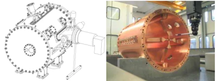
which allows using a cheaper copper. The low frequency (88 MHz) makes it possible. A 1-m long prototype is under construction to verify its feasibility and control the construction cost (Figure 3).
To do so at low cost, it was found that we could use a 5-cm thick tube as the external tank of the RFQ. The vanes are bolted to the tube with metallic vacuum joints and RF joints. The vanes being dismountable, it gives an interesting possible evolution of the RFQ.
Figure 3 : SPIRAL 2 RFQ prototype cavity The difficulty lies in the fact that we may need RF joints. 2D and 3D calculations were made with SUPERFISH and SOPRANO. They showed that the transverse current density is very low (22 A/cm) while we expect up to 38 A/cm on the vane extremities (Figure 4). High power tests will be made with and without the RF joints to verify their utility.
Figure 4: 3D view of the power deposition The prototype is chosen as the cell 253 of the final RFQ (113kV, for Q/A=1/3) the most demanding from the RF point of view. One of the four vanes is modulated. RF calculations were made using several codes : SOPRANO, MicroWave Studio and HFSS. They gave comparable results on the Q factor and on the power consumption (within 5%):
Soprano Q0 14 580 MicroWave Studio 15 040 HFSS 14 650 Power consumption 37 kW
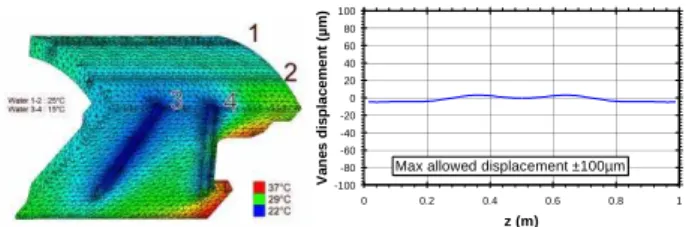
Vanes and external tubes will be water cooled with two separate water circuits, and the cavity frequency will be adapted using the water temperature. The vane circuit use simple water plungers. Under full operation, the vane displacement remains lower than 10 µ m with a temperature difference of 13.5°C for Q/A=1/3 beam and 7°C for the deuteron beam. Calculations were obtained using CATIA as the 3D mesh generator, SOPRANO-Vector Fields [7] for the power deposition and then with CASTEM for the cavity deformation [8].
Proceedings of EPAC 2004, Lucerne, Switzerland
-100 -80 -60 -40 -20 0 20 40 60 80 100 0 0.2 0.4 0.6 0.8 1 z (m) V a n e s d isp la cem e n t ( µ m )
Max allowed displacement ±100µm
Figure 5 : Temperatures and vane displacement The prototype is a nice realisation under achievement. The measurements give vane tips globally within ±25 µm of their theoretical positions with few points up to
±50 µm (measured before the final vacuum test). It will
be tested under full power (40 kW) first at INFN-LNS in Catania (Sicily), then in the IN2P3-LPSC Grenoble when the SPIRAL 2 project has received its own RF amplifier. At the LNS we will test the crucial point of the RF joint before the official end of the study. In Grenoble next year, we will measure the vane displacement in operation and the temperature elevations. The diagnostics includes 30 thermocouples, even on vane extremities, IR CCD camera (mapping of the vane temperatures), view ports for direct optical measurements and X-ray detections. Comparisons will be made with the 3D codes.
SPIRAL 2 RFQ
The final RFQ will be made of five 1-m long sections. The evolution of the mean aperture and vane voltage along the RFQ implies a modification of the cavity shape from cell to cell, to adjust the frequency. This could be done either by modifying the bottom of the cavity or by changing the vane shape.
One geometrical parameter has been selected for profile tuning taking into account ease of machining: this parameter is adjusted piece-wise linearly to best fit the required voltage profile at lower cost. Fine tuning will be obtained with standard stubs. The number of stubs, their spacing and their diameter are directly related to the desired voltage accuracy (±1%).
0 5 10 15 20 25 30 35 0 5 10 15 20 25 30 35 Cell 006 Cell 253 cm cm cm
Figure 6 : optimized shape of the final RFQ most significant cells.
Once frequency, general cross-section and RFQ length (5.077 m) have been chosen, the question of RF stability is to be addressed. The stability analysis describes the ability of the RFQ to sustain minor deformations (due to
thermal stress for instance) without perturbing the voltage profile. Excessive quadrupole-like perturbations can be prevented by RFQ segmentation, and dipole-like perturbations are reduced with properly tuned rods inserted in end-cells (and coupling-cells, if any). Analysis clearly shows that the SPIRAL 2 design is naturally stable w/r to quadrupole-like and dipole-like perturbations. Neither segmentation nor dipole rods are needed, which is favourable to cost-savings [9].
Figure 7 : Artistic view of the final SPIRAL2 RFQ
ACKNOWLEDGEMENTS
The SPIRAL 2 RFQ group is particularly grateful to the IPHI team that designed and built the IPHI RFQ and the IPHI DTL hot model for their assistance and participation.
The RFQ group wishes to thanks the INFN - LNS for hosting us for the RF hot test, with special thanks to A. Caruso and D. Riffugiato.
REFERENCES
[1] SPIRAL and SPIRAL 2 project, http://www.ganil.fr [2] R. Duperrier, F. Marti, “Power consumption comp.
between different RFQ structures in favour of the RIA project”, MSU note, Nov. 2002, 12 pages.
[3] R. Duperrier et al. "Status report on the beam dynamics developments for the SPIRAL2 project”, this conference
[4] W. D. Cornelius, “CW Operation of the FMIT RFQ Accelerator”, p 3139, Proc. of the 1985 Particle Accelerator Conf.
[5] P.-Y. Beauvais., “Recent evolutions in the design of the French High Intensity Proton Injector (IPHI)”, This conf.
[6] J. D. Schneider, “A review of high beam current RFQ accelerator and Funnels”, p.128, Proc. of the EPAC’98 Conference
[7] O. Delferriere, Design and 3D optimization of SPIRAL2 RFQ : Prototype definition, I-002817-V1 [8] D. Leboeuf, "Comportement thermo-mécanique du
RFQ prototype de SPIRAL2", sept 25, 2003
[9] A. France, “Theoretical analysis of capacitance and boundary condition errors on RFQ voltage profile” EDMS document I-002386 v.1.
Proceedings of EPAC 2004, Lucerne, Switzerland