HAL Id: cea-02873049
https://hal-cea.archives-ouvertes.fr/cea-02873049
Submitted on 18 Jun 2020HAL is a multi-disciplinary open access archive for the deposit and dissemination of sci-entific research documents, whether they are pub-lished or not. The documents may come from teaching and research institutions in France or abroad, or from public or private research centers.
L’archive ouverte pluridisciplinaire HAL, est destinée au dépôt et à la diffusion de documents scientifiques de niveau recherche, publiés ou non, émanant des établissements d’enseignement et de recherche français ou étrangers, des laboratoires publics ou privés.
Jules Horowitz Reactor
Daniel Parrat, G. Ducros, L. Ferry, P. Manen, Y. Zerega
To cite this version:
Daniel Parrat, G. Ducros, L. Ferry, P. Manen, Y. Zerega. Measurement of Fission Products and Chemical Species released by Experimental Samples irradiated in the Jules Horowitz Reactor. IGORR 2014 - The 16th International Group Operating Research Reactors Conference, Nov 2014, San Carlos De Bariloche, Argentina. �cea-02873049�
1
Measurement of Fission Products and Chemical Species released
by Experimental Samples irradiated in the Jules Horowitz Reactor
D. Parrat1, G. Ducros1, L. Ferry2, P. Manen2, Y. Zerega3
1) CEA, DEN, DEC, Fuel Research Dept., Building 151, CEA Cadarache F - 13108 Saint Paul lez Durance, France
2)CEA, DEN, DER, Reactor Studies Dept., Building 1222, CEA Cadarache F - 13108 Saint Paul lez Durance, France
3) Aix-Marseille Université, LISA EA 4672 Centre de Saint Jérôme – Service 461 F - 13397 Marseille Cedex 20, France
Corresponding author: daniel.parrat@cea.fr
Abstract. Experiments on nuclear fuels and materials in MTRs are a mandatory step for supporting their characterization and qualification before introduction at industrial scale in power reactors. They are the most often carried out in irradiation loops and capsules embarking a lot of instrumentation, either on-line or by integration. Besides measurement of local irradiation conditions (fast and thermal neutron flux, coolant temperature and pressure, stress applied to experimental load etc.), behavior of sample is monitored thanks to specific sensors measuring on-line important parameters for models and codes. However it presents a lot of constraints such as miniaturization, robustness, adapted measurement range with requested accuracy, negligible drift, materials compatibility etc. which can cause technical issues for long duration experiments. Some of these issues can be overcome by equipping with lines either the sample (internal free volume…) or the surrounding connected volumes (coolant pipe, gas gap…). Their role is to collect and route the fluids to specific out-of-pile measurement means which monitor by on-line and delayed techniques specific chemical elements and isotopes released by the sample: fission products, fissile material, activation or corrosion isotopes or molecules, either in normal conditions (high demanding conditions, power transients, innovative coolant chemistry, first barrier loss…) or during safety tests with sample damage (loss of coolant, power injection…). This paper presents the interest of such measurements for supporting the development process of nuclear fuels and materials. Relevant design data for implementation on experimental samples are given. Analysis equipment recommended to be installed in the Fission Product Laboratory and the Chemistry Laboratory of the Jules Horowitz MTR, for activity and for atoms counting, are presented. Such laboratories are underlined as a key service offered by a modern multipurpose irradiation infrastructure.
1. Introduction
To develop a new fuel product or a new nuclear material before using it at an industrial scale in a power reactor is a long process (10 to 15 years), ranging from the determination of physical properties of the material itself out of neutronic flux up to its qualification during accidental-type sequences as representative as possible of reactor conditions. Licensing file of an “optimized” fuel (i.e. which presents a slight evolution compare to an already used fuel, for clad alloy or microstructure…) can refer to previous qualification program results as a robust reference basis. Expected behavior difference can be predicted by qualified simulation models confirmed by surveillance programs on “precursors” (lead test assemblies) irradiated in power reactors and examined through post-irradiation examinations (PIEs).
However, for innovative fuels or materials, or for new irradiation conditions, qualification needs go often beyond the authorized operating domain of industrial reactors (in terms of geometry, burn-up or dpa, power level or power variation rate, behavior after loss of first barrier integrity etc.). Moreover, in some cases, the requested information is not accessible by PIEs. Additionnally PIE results are obtained in cold conditions, so could be hardly transposed to reactor operating conditions.
2
When such issues can jeopardize the qualification demonstration, irradiations in Material Test reactors (MTRs) are mandatory and become in practice the basis of the whole development process [1]. They are the best approach for studying some pending questions about fuel and material behavior such as:
Evolution of fuel basis properties under neutronic flux, versus temperature, flux level and integrated dose: i) mechanical properties (creep, dislocation density, gaseous swelling…) ii) thermal properties (thermal conductibility, thermal expansion, heat capacity), and physical-chemical properties (densification, oxygen potential…),
Oxygen and hydrogen pickup in cladding materials, and corrosion layer development in relation with the local chemistry,
Cracking initiation and propagation in metallic alloys, assisted by irradiation,
Thresholds versus fast neutrons integrated dose, burn-up or temperature (e.g. fission gas release, clad or neutronic absorber swelling, MOX agglomerate restructuration …), Unexpected or insufficiently modelled phenomena (e.g. fuel cracking network,
fuel-cladding strong contact, He behavior),
Chemical forms and distribution of fission products other than noble gases, and their release under temperature or power transients in specific atmospheres (oxidizing or reducing).
On a more general approach, quantification of margins versus safety criteria or versus the loss of the product reliability is also of prime interest and can be studied through separate effect irradiations. Moreover, MTR experiment objectives are now strongly related to the modeling needs, which become progressively the driving force for implementing such tests.
2. Use of instrumented samples in irradiation: interests and limitations
Capability to answer the above questions implies to implement experimental programs respecting a progress regarding knowledge acquisition. In general terms irradiation process starts with a purely separate effect approach, firstly on properties accessible one by one (or after coupling a few of them if only embedded effects are accessible), and secondly on global macroscopic behavior (thermal and geometrical stability, macrocracking…). Following this initial step, irradiation process integrates progressively cumulated effect of more and more environment parameters (driven by neutronic flux, temperature and pressure field, coolant chemistry…) and by testing samples representative of the industrial product (e.g. a short rod). Finally specific tests are carried out to assess the sample behavior at the limits of normal conditions and in off-normal conditions. Safety tests are included in this last category.
For that aim, experiments are often carried out in irradiation devices such as loops and capsules [2]. Loops can be “integrated” (pump is embarked in the device) or with an out-of-pile circuit (with pump, heat exchanger, pressurizer, chemistry control etc.). Flow rate can be initiated by natural or by forced convection. Integrating recent progresses in miniaturization and radiation resistance, the test section and the sample are equipped with embarked instrumentation. Sensors or detectors can deliver information on-line or in real time, or by integration.
A first category of instrumentation is devoted to monitor the local environment of the sample in irradiation. Fast and thermal neutron flux levels and profiles, gamma energy deposit, coolant temperature, pressure and flow rate, stress applied to the sample, temperature of an external gas gap, are the main monitored parameters. Other measurements are accessible in an out-of-pile area without detriment to the representativeness: e.g. coolant chemistry and radionuclide concentrations routed by coolant.
3
A second category of instrumentation is directly connected to the sample. A lot of physical or chemical parameters can be monitored, on-line when it is technically feasible. Instrumentation can be either fixed on a sample component (clad temperature, elongation or strain, crack initiation and propagation on a specimen…) or introduced in the sample (central fuel temperature, fuel elongation) or in relation with the sample inner free volume (gas total pressure, differential pressure…). In practice nuclear instrumentation in MTRs (for in-core locations or for experiments in core or in reflector), or more generally in harsh and closed environments imposed by in-reactor nuclear measurements (fission or fusion), constitutes a specific innovation and development domain, with a lot of remarkable progresses in the recent years. This paper doesn’t describe instrumentation physical principle and technology, which are topics of numerous other papers. Only a few recent review papers are mentioned here in ref. [3], [4], [5], [6].The domain is in continuous progress. In particular measurement methods without contact (e.g. by optic fibre [7] or ultrasonic waves [8]) are capable to provide new information under neutron flux.
However there are some limitations in the use of this in-situ instrumentation. Miniaturization is often presented as the most penalizing one. Manufacturing or assembly of small and fragile pieces can include mounting difficulties, especially if the operation is done in hot cell. The break risk is then often enhanced with long sample transportation. Another issue is to not interfere with the sample behavior, by modification of the sample design or by impacting thermal (gamma heating in the detector material) or stress (welding or fixation mode) fields. In some cases instrumentation adds a free volume to the monitored one, and this provokes a drop in the sensitivity or accuracy levels. Lifetime of detectors is also a strong limitation if the experiment lasts several months or years. This obliges either to use well proven designs and robust technologies (often with a decrease of measurement quality or accuracy) or to insert redundancy in the test section for key measurements. This complicates the test section design. Finally one can mention other drawbacks. One of them is isotopic evolution of detecting material by activation or transmutation, which can affect the response signal as a drift under neutron flux. Another one is the input of technical specifications imposed by some MTR experiments carried out for supporting R&D on new power reactor systems (e.g. for Generation IV systems) or for developing a more robust fuel element (e.g. accident tolerant fuels). Irradiation conditions can be at the limit of measurement level or range for some qualified detectors. A third and last drawback mentioned in this short review concerns the chemical compatibility between the sensor components and the surrounding materials or atmosphere. Some eutectics or new compounds can be formed (e.g. interaction of stainless steel and carbon) or large oxidation can occur e.g. in presence of steam or oxidizing atmosphere during a safety test.
3. How fission product measurements can enhance a MTR experiment quality?
It is clear that for a lot of data, use of instrumentation as described above is the only one way to gain information on sample behavior under irradiation. Innovation is then the driving force to overcome mentioned limitations. However some information can be substituted or completed by quantification of some nuclides released specifically by the sample. The topic concerns mainly (but not only) irradiations of fissile samples because of formation of fission product (FP) isotopes inside the material. Release of fission products (FPs) out of a fuel material gives specific knowledge on the fuel behavior and evolution of the fuel microstructure in the experiment conditions. Many parameters govern migration and release of such isotopes in the material: temperature level and gradient, burn-up, oxygen potential,
4
presence of additives or dopants in fuel playing the role of “traps”, gain size, element concentration outside the fuel, external hydrostatic constraint on fuel etc.
To separate and quantify activated parameters, a measurement strategy consists to recover released FP isotopes inside or in the vicinity of the sample, and then to route them to a measurement apparatus located in an out-of-pile zone. Basically, measurement of concentrations in the routing fluid allows, after deconvolution of the fluid transfer characteristics (flow rate, transit time etc.), knowing the release rate (expressed in atoms/s) of interest isotopes out of the fissile material. Moreover isotope ratios, in particular on radioactive ones having same chemical behavior, allow using radioactive decay as a chronometer. When the formation mode and distribution are known, ratio results constraint the possible migration and release mechanisms activated. Release quantification can also be used more directly to verify if a safety criterion is fulfilled or not, or to provide codes with input data. Main information gained through this type of measurement can be resumed below:
Pressure evolution in hot conditions in the inner free volume of the fuel element (rod, pin...) caused by released fission gases (FG: xenon and krypton) and sometimes also by helium. This can be an issue limiting the lifetime of a fuel product in power reactor in nominal conditions,
Inner pressure can be also affected by power transients, provoking a release burst either due to the power change rate, or to the maximum power reached. This accounts for operational transients but also incidental conditions. This quantification, as the previous one, is driven by stable fission gases isotopes, largely more abundant than radioactive ones,
Radioactive source term immediately available for escaping in coolant in case of sudden first barrier loss of integrity. This concerns not only fission gases but (if coolant is a fluid such as water or sodium) other fission products, already present in the inner free volumes, which have a high volatility or which can be soluble in the coolant: I, Cs, Br, Te etc.
Radioactive source term permanently released at equilibrium (e.g. in the coolant) in case of continuous operation of the fuel element in a failed mode during normal operation. This release provokes activity in the primary circuit which has to comply with operating technical specifications of the reactor,
In some fuel element design (e.g. HTR particle), permeation of some FP isotopes (e.g. from Pd or Ag) through the first barrier at high temperature,
Detection of fuel element failure degradation in normal operation (e.g. after interaction with coolant), with starting of fissile material release,
Radioactive source term released during accidental transients with fuel element degradation. This concerns FPs and other chemical compounds build up after interaction between fuel element and surrounding structures (guide tubes, neutron absorbing material etc.). Release of fissile material can also occur and shall be quantified (quantity, size grading…).
Gaseous isotopes are of specific interest for measurement: they consist the most often in noble gases (Xe, Kr, He), without chemical reactions and with a low probability of deposit. Moreover they are not affected by the method of collection or of transfer (except for the radioactive decay and the spreading in the gas line). On a scientific point of view, they have got a good diffusion coefficient in the fissile material, with the property to form bubbles inside the grains or at the grain boundaries. So they are good indicators of the local fuel material behavior. Currently monitored radioactive isotopes have half-lives ranging from a few minutes to a few days, so they are performant for detecting changes in the release mechanisms and can be quantified by different counting techniques (see § 8).
5
4. Techniques for recovering fission products and chemical species in MTR experiments Two main techniques are used for implementing on a sample, on the test section, or on the coolant circuit a system for recovering FPs or other species:
4.1 Recovering thanks to a separate gas line
For gaseous isotopes (Xe, Kr, He, H2, CO2, CO…), the technique is quite simple and aims at
recovering the scientific information as near as possible of the release location. In practice, sample can be equipped with minitubes for inner free volume (if any) sweeping with a routing gas. A well-known design is a rod or pin geometry having end-plugs equipped with such lines (internal gas pressure measurement by gauge is not considered as a FG analysis technique). The same system can also be applied to a capsule containing samples and a gas volume. In this case the swept gas volume is outside the samples. This is applied to “open” samples (e.g. fuel disks) or samples without free volume (e.g. HTR compacts or pebbles). Another specific configuration is a sodium (or NaK) loop or capsule, or a LWR fuel device after a safety test (e.g. after a LOCA), where interest isotopes are recovered by sweeping of the in-pile inert upper gas blanket. For all configurations, routing gas then goes to measurement means described below. Sample cooling is obviously physically separated from the recovering circuit. As only gaseous FPs shall be measured in the out-of-pile circuit, a filter that blocks the volatile isotopes such as Br, I, Cs, Te is generally inserted in the gas line downstream of the sample. A dryer can also be used if there is a risk of residual steam transportation.
4.2 Recovering thanks to a line connected to the main coolant circuit
For measurement of all released isotopes or species, including heavy nuclei, a low and continuous coolant flow rate (liquid or gas) is derived from the main experiment coolant circuit and is routed to measurement means. Depending on irradiation device design, derivation can be located either in in-pile part or in cubicle. However this recovering technique is only adapted to elements for which deposit on line walls, or during transfer process, is negligible. In some cases (e.g. safety test) it is interesting to recover and to route the whole device coolant after the test, for measurement and build-up of a FP balance.
5. Strategies for transferring FPs and chemical species from in-pile part to measurement means
Two main transfer modes are used: the first one is based on a continuous sweeping at constant flow rate whatever the experimental conditions (in particular if the pressure drop of the experimental sample varies during the protocol). It allows measuring on-line atom concentrations of elements or isotopes in the routing fluid.
The second one let isotopes accumulate in the experimental sample thanks to closed valves for a given period of time. Then routing transfers the totality of accumulated information in a very short period of time (a few seconds or tens of seconds) directly to a measurement technique or more often to a pre-voided capacity or trap, for sampling and storage.
The first mode is preferable because it allows continuous monitoring of the coolant or of the fluid in contact with the sample under neutron flux. A release evolution is immediately identified and can be correlated to the irradiation process or parameter change. However it necessitates sufficiently high isotopic or elemental concentrations to be detectable on-line or semi on-line (i.e. successive countings with short integration time for each). If not, the second mode shall be used and the objectives are to quantify i) mean release rate of each isotope
6
since the previous sweeping when the sample is operated at constant LHGR and ii) fractional release of isotopes after a power variation or an external transient (e.g. change in coolant temperature and/or pressure).
There is no need to have a short transit time, because sufficient information is deduced from short and middle half-life isotopes. Very short half-lives (less than about one minute) are also very sensitive to transit time and to a spreading due to fluid velocity distribution in the routing line. So concentration values are often affected by a large uncertainty. Moreover they cause issues for radioprotection in out-of-pile circuits. In practice a transit time between roughly 3 to 15 minutes is generally used, if necessary by adding delay lines.
Flow rate in the line is generally low, and is dependent from the type of fluid. For a routing gas flow rate is about one to a few cm3/s STP. For liquid coolant, the flow rate is higher (10
l/h to a few tens of l/h). This allows using small diameter lines and avoiding transfer perturbation phenomena such as retro-diffusion. However, to avoid FP deposits during the transfer, water lines shall be heated above about 150°C.
As the pressure drop is generally done by the experimental sample itself, the routing fluid pressure downstream the sample is low and shall only ensure the flow rate for a correct measurement, sampling or evacuation to waste lines. However the upstream inlet pressure can be high in case of high burn-up sample sweeping (more than 100 bars).
6. Interest isotopes to be measured
With respect to the input data given in the previous paragraph, interest FGs can be roughly classified in different half-life categories:
The “30 s group”: 90Kr (32.3 s) and 139Xe (39.7 s),
The “3 min group”: 89Kr (3.16 min) and 137Xe (3.84 min),
The “15 min to 1h group”: 138Xe (14.2 min), 135mXe (15,3 min) and 87Kr (76 min),
Above about 1h radioactive isotopes are considered as middle and long half-lives, which are not affected by the transit time between in-pile part and measurement/sampling mean. Because of their longer half-lives they can be concentrated in a sample if the detection threshold is not simply reached. Main isotopes in this class are: 88Kr (2.84 h), 85mKr (4.48 h), 135Xe (9.15 h), 133mXe (2.19 d), 133Xe (5.24 d), 131mXe (11.9 d),
The stable isotopes are the large majority of FGs. These are: 83Kr, 84Kr and 86Kr, 131Xe, 132Xe, 134Xe and 136Xe. Long half-life 85Kr (10.7 y) is often considered as a
stable gas (e.g. for pressure calculation). At high burn-up, they constitute a significant part of the total FP inventory in the fuel (about 30%).
When release occurs after fuel-coolant contact without significant dimensional change of sample, experimental results show that FP release from the failed fuel material is considerably higher than for a tight one (about 10 times in LWRs), and is considerably dependent from the rod LHGR. A large set of FPs can be released in coolant at a significant level. They can be classified into 4 main families, listed below for LWR nominal conditions and chemistry (middle and long half-lives radioactive isotopes of these elements have to be considered):
Noble gases : Xe, Kr
Volatile elements : Br, Te, I, Cs, Rb
Less volatile elements : Se, Sr, Mo, Tc, Ru, Rh, Ag, Sb, Ba Non volatile elements : Zr, Nb, La, Ce, Y, Nd, Pr, Eu
Release of non-volatile isotopes corresponds to a significant sample degradation (e.g. during a safety test) and is often accompanied by fissile elements (U, Pu, Am, Np, Cm) which are also
7
of interest but necessitate specific sampling and preparation before counting (except 239Np
and 241Am). Moreover they could lead to significant circuit operation and maintenance issues.
Above list is limited to FPs and consequently to fissile material samples. It can be extended to other sample types, through measurement of other radioactive or stable chemical compounds:
Release of corrosion or activation products (e.g. metallic oxides) due to chemical interaction between coolant and first barrier. This impacts the global radioactive level of primary circuit, especially when chemical conditioning of coolant is changed, Release of chemical species resulting of various interactions between materials
constituting the fuel element and impurities routed by coolant. One example is release of CO, CO2 species in a HTR circuit when there is air ingress in the gaseous coolant,
Quantification of tritium production, permeation or release out of specific targets is also of interest for some programs, for example in support to fusion technology.
7. Measurement methods for FPs and chemical species quantification 7.1. On-line measurement
Fluid transporting FPs is monitored when passing in front of a detector. A measurement chamber can be used in order to increase the fluid volume monitored and consequently to decrease the detection limit for a given FP. Monitoring can be:
Permanent, with an instantaneous analogic measurement, or with a given acquisition (or counting) time. In this case the delay between two integrations is null,
Semi on-line (periodic measurements), but at a frequency sufficiently high that lost information (during the “blind” periods) is negligible given the experiment's objectives.
Types of information gained (after signal assessment and calibration) by this technique are: The instantaneous release Ri(t) in atoms/s from the experimental sample for each
measured FP i, if the measurement can be carried out in a very short period of time, The mean release <Ri(t)> during the acquisition time, if the release does not vary
significantly during this period and can be considered as a “release at equilibrium”. Of course the time resolution to assess a physical phenomenon is the time between two successive acquisitions,
The integral release {Ri(t)*dt} of a release 'burst', if the relative burst profile and/or
the hydraulics of the sweeping line are well known.
For radioactive isotopes, activity signal is mainly due to short and middle half-life isotopes (typically less than one day), and long-lived isotopes are often not detectable.
7.2. Accumulation and sampling techniques
7.2.1. Accumulation techniques
FPs swept by the fluid are retained (or “trapped”) by a physical or a chemical process on a specific media. The media can be a filter (for aerosols, particles or grains), a resin (for ionised atoms) or an adsorption surface (e.g. activated charcoal or zeolite at liquid N2 temperature for
fission gases). This technique presents three main advantages:
To accumulate a larger number of atoms than for on-line monitoring, this can be measured further more easily. In case of radioactive isotopes, accumulation is balanced by the radioactive decay, and maximum possible atom inventory is obtained after about 4 times of the half-life, and then is more or less constant,
8
To concentrate them in a small volume, by the design of the retaining material. This enables the volume to be placed closer to the detector, for increasing the signal level and consequently to lower the detection limits,
To wait after the sample accumulation and perform the measurement “off-line”. This allows some interfering short-lived isotopes to die away and reduce the background. This technique is worthwhile implementing when experiment deals with very low concentrations or quantities of FPs and the aim is to improve measurement detection threshold. This improvement results either from concentration of isotopes of interest, or by upstream elimination of isotopes which would degrade the measurement quality.
However, some precautions have to be pointed out:
Trapping time can vary, from a few minutes to several hours (depending on irradiation mode and expected concentration level to be attained). Assessment can be made using either of the following hypotheses:
- The release can be considered as nearly constant during the accumulation time, and the result represents the mean value <Ri(t)> during this time, as defined
above,
- If FP release is due to parameter change (transient…), release time history can be a 'burst' much shorter than accumulation time. Consequently trapped quantity will represent only the total released quantity {Ri(t)*dt}, without knowing detailed
release time history (except if several samples can be taken during the burst), In case of radioactive isotope trapping, signal due to short half-life isotopes will be
low compared to the long half-life isotopes one. This technique favours the detection of this longest-lived isotope group (a few hours or longer),
Trapping flow rate and accumulation time are dependent on the media efficiency and on the known detection limits of the technique and the apparatus geometry. These parameters have to be defined prior to going into operation,
Chemical form of the element trapped shall also be well known to establish the efficiency of the operation,
Trapping of noble gases at liquid N2 temperature surfaces implies that there is no
water vapour in the carrier gas, and consequently a drying unit shall be inserted upstream of the trapping point. Other gases with boiling points much higher than liquid N2 (77°K) such as CO2 (sublimation point 195°K) must also be absent or be
removed from the gas stream. Finally cold traps are re-generated occasionally by heating at 200 - 250°C while swept with an inert gas.
7.2.2. Sampling techniques
The objective is to sample a given quantity of the fluid carrying the FPs for later measurement. This technique is rather classical, because the container can be either inserted on the routing line (and can be by-passed when not in use), or can be located at the end of a “sampling line” that is normally isolated. The sampling is generally carried out at room temperature, and the container can be pre-voided or flushed with the carrier gas to facilitate the sampling and to avoid fluid or sample losses (in this case the final pressure can be kept under the atmospheric pressure). The sampling quantity is very variable, depending on FP activity level and on sampling volume:
In case of water coolant, it can range from about 2 cm3 up to about 100 cm3,
In case of a gaseous fluid, the order of magnitude is from about 10 cm3 STP up to
about 500 cm3 STP.
However, there are some generic precautions:
9
Air-tightness is imperative, as the fluid contains gaseous isotopes, which may need to be stored several months before the last measurement (about 6 months is common), With liquids (especially water) the sampling flow rate and quantity should avoid an
immediate or delayed degassing inside the capsule,
Sampled quantity has to be adapted to expected information and to measurement range of analytical device, to avoid a subsequent transfer (dilution, purification…),
Sample should be kept until the data are complete and have been verified. 8. Fission product and chemistry analysis laboratories in the Jules Horowitz MTR
It is recommended to carry out FP measurements in a purpose-built laboratory attached to the MTR. This architecture presents a lot of advantages: benefit of common systems (e.g. shielded cells or glove boxes with suitable radioprotection), gathering of transfer lines (minimizing feedthroughs, connecting boxes, radioprotection and lines corridors), proximity of measurement devices, monitoring of same fluid by several techniques etc. Moreover, FPs can be trapped efficiently in the Laboratory and this limits quantity of activity transferred downstream to cubicle tanks. Only in very specific cases, i.e. when a specific property of the isotope can affect the measurement (e.g. too quick decay, deposit on line wall, change in aerosol size…), it should be necessary to install the measurement device as near as possible to the irradiation device outlet or in the cubicle when the main coolant transit time is short. It is the case e.g. for measuring delayed neutron emitters (DND method).
Complying with this principle, the Jules Horowitz MTR (JHR) will be equipped with 2 FP-devoted laboratories [9]:
8.1. Fission product laboratory
The fission product laboratory (FP Lab.) will be solely devoted to on-line and delayed measurement of radioactive and stable fission products, their temporary trapping for further measurements, and their purification and storage as a waste. This infrastructure will be based on shielded cells connected either to irradiation devices or to experimental cubicles, or to the both. Depending on the device and the type of fluid to monitor, measurement can be carried out either on the fluid coming directly from the in-pile part (e.g. coolant or device upper gas blanket) or on fluid present in the cubicle (e.g. for sampling). Equipment study of this laboratory is still in progress, and so far four main components are planned.
A shielded cell devoted to measure radioactive and stable fission gases by on-line gamma spectrometry and on-line mass spectrometry (this new device is under development and is presented in § 8.4). This cell will also contain a set of traps coolable until liquid N2 temperature to retain Xe and Kr,
A shielded cell capable to welcome coolant routing an elevated fission product concentration. Measurements on the passing fluid will be based on on-line gamma spectrometry, delayed neutron detection (DND) and sampling,
A third shielded cell connected to the two previous ones will welcome the samples taken and will deal with the delayed counting and the short-term storage between two measurements,
A ventilated glove box for counting gas coolant or sweeping gas routing low concentrations of noble gas isotopes (Xe, Kr), or other gases (He, CO, CO2…).
These components will be progressively installed in the FP Lab., depending on the expressed needs for programs coming from future end-users.
10 8.2. Chemistry laboratory
This laboratory will deal mainly with the experimental part of the JHR. Its role will be: Verify that loop coolant chemistry characteristics are within specifications,
Welcome samples taken in the FP Lab. or in experimental cubicles, and to quantify isotopes or elements, relevant for the scientific objectives of an experiment, thanks to specific measurement systems (delayed measurement),
Analyse gaseous and liquid wastes released by the experiments, Support the operation of the JHR.
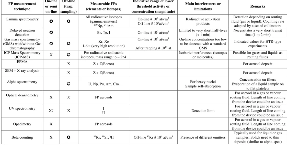
8.3. Recommendations on techniques to be installed in JHR analyses Laboratories
So far the scientific equipment of these both infrastructures is not completely defined. However a first set of recommendations regarding the type of valuable techniques to install in a modern MTR has been released at the European level thanks to the European program “MTR+ I3” (6th Framework programme) [10]. These recommendations have been updated
and are presented in table 1 below.
8.4. Innovation on FP measurement by on-line mass spectrometry method with implementation in JHR
Techniques listed in table 1 are not described here due to lack of place, but they are largely implemented in laboratories. Some details and applications to FPs are given in [10]. Besides these means, collaboration between Aix-Marseille University (AMU) and CEA Cadarache is on-going for developing an innovative on-line mass spectrometry device devoted to measure FP release at very low concentrations in JHR experiments [11].
Mass spectrometry is an interesting tool enabling the identification and quantification of both chemical compounds and stable/long-lived isotopes in numerous nuclear research applications and facilities. With on-line mass spectrometry, the gas-sampling device must ensure the pressure drop between the line at about 1 bar and the mass spectrometer vacuum chamber at 10-7 torr (1.3*10-5 Pa) with a fast response and without mass segregation. Typically, that requires a double-stage pressure and a double-flow inlet device using a capillary and a molecular leak, and two separated pumping devices. Such an inlet device has been implemented in a mass spectrometer using a triple quadrupole analyser [12]. This mass spectrometer is the first collaboration target between AMU and CEA. It will measure at 1 ppm the release kinetics of Kr and Xe isotopes from irradiated fuel material submitted to thermal transients in the MERARG II facility at CEA Cadarache [13].
Important scientific works have been developed by the Japan Atomic Energy Agency and some Japanese Universities to analyse the cover gas of fast neutron reactors in order to detect and locate leaks of nuclear core components. The multi-photon ionisation is a very sensitive (almost 100%) and selective ionisation method, suitable for ultra-trace analysis. With a fast pulsed-valve and a multi-photon ionisation source coupled to a time-of-flight (TOF) mass spectrometer, 1 ppt detection level has been obtained for the whole of Kr and Xe isotopes in Ar carrier gas without isobaric interference [14].
Besides FPs trace analysis, low-mass detection (from 1-6 u) is also of a great concern in fusion and fission domains for the detection of hydrogen and helium isotopes and associated compounds. The highest performances in term of mass-resolution must be reached by the analyser to separate 3He+ - T+ (0.00002 u) and HD+ - H
3+ (0.00165 u), for instance. Few
manufacturers propose advanced triple quadrupole mass-filters: these devices are able to separate helium and deuterium (0.026 u) [15], [16]. Research works are carried out to increase the mass-resolution of mass-filters [17], [18] and ion trap [19]. The ion trap operated in Fourier Transform mode proves to be an interesting tool to analyse hydrogen and helium isotopes as resolution increases at low masses [20].
11 FP measurement technique On-line or semi on-line Off-line (trap, sampling) Measurable FPs (elements or isotopes)
Indicative range of lower threshold activity or concentration (magnitude)
Main interferences or
limitations Remarks
Gamma spectrometry
All radioactive isotopes (gamma emitters)
239Np, 241Am
On-line # 108 at/cm3
Off-line # 106at/cm3
Radioactive activation products
Detection depending on routing fluid (gas or liquid). Counting rate
adapted by a set of collimators Delayed neutron
detection Br, Te, I On-line # 10
7 at/cm3 Limited to very short half-lives
(< 1 min)
Necessitates a very short transit time (1 to 2 min) Gas mass spectrometry
(GMS) with/without Gas chromatography
1-6 u (very high resolution) Kr, Xe On-line # 10
7 at/cm3
After trapping # 1011 at
On-line concentrations too low to be detected with a standard
GMS
Indicated values for HTR-type experiments
ICP Mass Spectrometry
(ICP-MS) X
For radioactive and stable isotopes, mass range: 6 – 254
Isobaric interferences (isotopes or molecules)
Possible for gases and liquids as routing fluids
EPMA
X Z > Z(Boron) For aerosol deposit SEM + X-ray analysis
X Z > Z(Boron) For aerosol deposit Alpha spectrometry
U, Np, Pu, Am, Cm For heavy nuclei Sample self-absorption
Concentration on filters Evaporation of a liquid sample on
to flat platelets Optical densitometry
X X FP aerosols
For aerosol in a gas or vapour routing fluid. Length of line coming
from the device could be an issue UV spectrometry
X? X I
U Detection limit
For aerosol in a gas or vapour routing fluid. Length of line coming
from the device could be an issue Opacimetry X FP aerosols
For aerosol in a gas or vapour routing fluid. Length of line coming
from the device could be an issue Beta counting X 85Kr, 90Sr, ³H Off-line 85Kr # 106 at/cm3 Presence of different emitters
Typically used for liquid or gas samples. Solids need to thin deposits (similar to alpha-spec)
Method considered as necessary to implement in JHR X Method recommended to implement in JHR
12 9. References
[1] Parrat, D., et al., “Nuclear fuels and materials qualification programs in the European Jules Horowitz Material testing Reactor”
Proc. of the WRFPM - Topfuel 2013 Conference, September 15-19, 2013, Charlotte (NC, USA) [2] Blandin, C., et al., “Fuel and material irradiation hosting systems in the Jules Horowitz Reactor” IGORR-15 Conference, October 13-18, 2013, Daejeon (South Korea)
[3] Solstad, S., et al., “Instrument capabilities and developments at the Halden Reactor Project” Nuclear Technology, 173, 78 (2011)
[4] Kim, B., et al., “Review of instrumentation for irradiation testing for nuclear fuels and materials” Nuclear Technology, Vol. 176, pp 155-187, November 2011, Review paper
[5] Villard, JF., “Innovative in-pile instrumentation developments for irradiation experimets in MTRs” IGORR-10 Conference, September 12-16, 2005, Gaithersburg (Maryland, USA)
[6] Villard, J.F., et al., “Innovations for in-pile measurements in the framework of the CEA-SCK•CEN Joint Instrumentation Laboratory”
ANIMMA 2009 International Conference, June 7-10, 2009, Marseille (France)
[7] Cheymol, G., et al., “Fiber optics for metrology in nuclear research reactors : applications to dimensional measurements”
ANIMMA 2009 International Conference, June 7-10, 2009, Marseille (France)
[8] Augereau, F., et al., « Piezoceramic reliability for ultrasonic transducers in nuclear environments” European Workshop on piezoelectric materials, July 16-18, 2008, Montpellier (France)
[9] Parrat, D., et al., “Non-destructive examination benches and analysis laboratories in support to the experimental irradiation process in the Jules Horowitz Reactor”
IGORR-13 Conference, September 19-23, 2010, Knoxville (TN, USA)
[10] Parrat, D., et al., “FP measurement techniques on fuel experiments in a modern MTR”
JRA2–WP2.5 “fission gas measurement”, MTR+ I3 EU program FI6O-656-036440, September 2008 [11] Zerega, Y., et al., “Analysis of fission gas release kinetics by on-line mass spectrometry”
IEEE Transactions on Nuclear Science 59 (2012) 1323-1334
[12] Guigues, E., et al., “On-line mass spectrometry measurement of fission gas release from nuclear fuels”
Submitted to Thermal Transients. IEEE Transactions on Nuclear Science (2014) under press
[13] Guigues, E., et al., “Fission Gas Release (FGR) from nuclear fuel: Xe-Kr isotope monitoring at 1 ppm by on-line mass spectrometry”
HOTLAB-2014, 51st Annual Meeting of the Working Group "Hot Laboratories and Remote Handling", September 21- 25, 2014, Baden, Switzerland
[14] Iwata, Y., et al., “Improvement of the resonance ionization mass spectrometer performance for precise isotope analysis of krypton and xenon at the ppt level in argon”
International Journal of Mass Spectrometry 296 (2010) 15-20
[15] Extrel ; Gas Analysis, Helium / Deuterium Analysis, MAX50 and MAX120 Series ; http://www.extrel.com/Module/Catalog/ApplicationsCategory/default/Gas_Analysis/Helium___Deute rium_Analysis?id=64 (June, 1st, 2014)
[16] Hiden Analytical ; qRGA ; http://www.hidenanalytical.com/en/for-residual-gas-analysis/qrga-a-system-for-tokamak-torus-fusion-research#overview (June 1st, 2014)
[17] Sreekumar, J., et al., “A quadrupole mass spectrometer for resolution of low mass isotopes” Journal of the American Society for Mass Spectrometry 21 (2010) 1364-1370
[18] Syed, S., et al., “Factors influencing the QMF resolution for operation in stability zones 1 and 3” Journal of the American Society for Mass Spectrometry 23 (2012) 988-995
[19] Orient O., J., et al., “Baseline resolution of 1,2H and 3,4He isotope mixtures with a Paul ion trap mass spectrometer”
Review of Scientific Instruments 74 (2003) 2936-2938
[20] Zerega, Y., et al., “Chapter 9: A Fourier Transform Operating Mode Applied to a Three-Dimensional Quadrupole Ion Trap. In Practical aspects of trapped ion mass spectrometry”
Theory and Instrumentation, volume IV, J. F. J. Todd; R. E. March, Eds.; CRC Press: Boca Raton, 2009; 469-522