Design of a Biomechanically Synergistic Exotendon Suit
by
Carmen Marten-Ellis Graves S.B. Mechanical Engineering
Massachusetts Institute of Technology, 2011
MASS AI ETrS INS E
OF TECHNOLOGY
NOV 12 2013
DBRARIES
SUBMITTED TO THE DEPARTMENT OF MECHANICAL ENGINEERING IN PARTIAL FULFILLMENT OF THE REQUIREMENTS FOR THE DEGREE OF
MASTER OF SCIENCE IN MECHANICAL ENGINEERING AT THE
MASSACHUSETTS INSTITUTE OF TECHNOLOGY
SEPTEMBER 2013
© 2013 Massachusetts Institute of Technology. All rights reserved.
Signature of Author:
Department of Mechanical Engineering ,,August 9, 20J3
Certified by:
bae Kim Assis t Professor of Me ical Engineering Thesis Supervisor
Accepted by:
favid E. Hardt Ralph E. and Eloise F. Cross Professor of Mechanical Engineering Chairman, Department Committee on Graduate Students
.I-- I z -__
Design of a Biomechanically Synergistic Exotendon Suit
by
Carmen Marten-Ellis Graves
Submitted to the Department of Mechanical Engineering on August 9, 2013 in partial fulfillment of the Requirements for the Degree of Master of Science in
Mechanical Engineering
Abstract
The focus of this thesis is on the design, development, and evaluation of a lightweight,
exotendon suit for load carriage. The suit is intended to be worn underneath the wearer's own clothes for use in a military setting, while reducing the energy expenditure of the wearer. A simple exotendon suit architecture was designed and implemented, consisting of two knee braces, a length of polypropylene tendon, a belt, two electro-magnet clutches, and a control box. The electro-magnet clutches are mounted at the waist and tendons are used to apply the
actuator's force to the wearer's ankles. This is advantageous, as many current exoskeletons mount actuators at the ankles, requiring a greater amount of additional energy expenditure. Testing was performed at the Wyss Institute for Biologically Inspired Engineering Motion Capture Laboratory. Metabolic power was tested using a COSMED K4b2 system and surface electromyogram (sEMG) data was collected using a Delsys Trigno system. Five male subjects participated in six trials, walking on a treadmill at 1.25 m/s, carrying a 20 kg load in a standard military rucksack. The six trials consisted of three conditions: street clothes, exosuit worn but unpowered (passive), and exosuit word and powered (active). Results of the tests were inconclusive. There was no significant evidence that powering the exosuit has a positive or negative effect on the wearer's energy usage.
Thesis Supervisor: Sangbae Kim
Acknowledgements
I would like to thank Professor Sangbae Kim for all of his support throughout this project. He has provided me with the resources to allow this project to become an invaluable experience. Thanks to Dr. Hae Won Park and Dr. Dong Jin Hyun for their assistance with the suit's
controller and thanks to Professor Conor Walsh, Dr. Patrick Aubin and Dr. Stefano de Rossi for their help with experimental testing at the Wyss Institute for Biologically Inspired Engineering Motion Capture Laboratory.
Special thanks to my mother, my father, my brother, and Delmy for never giving up on me. And thanks to Joshua Ramos for standing by me and supporting me when I thought I would not finish. You all mean so much to me. Love you all.
Table of Contents
A bstract ... 3 Acknowledgements... 5 Table of Contents ... 7 List of Figures... 9 List of Tables ... 13 1 Introduction...152 Exotendon Suit Design and Fabrication ... 17
2.1 Suit Architecture ... 17
2.2 Tendon Routing and Knee Joint... 18
2.3 Clutch Design... 20
2.3.1 Electro-Permanent Magnet ... 20
2.3.2 Electro-M agnet Clutch... 22
2.4 oc - pr g ... 23
2.5 Full Clutch Design ... 24
2.6 Electro-M agnet Cone-Clutch Prototype... . 26
2.7 W iring and Control... 30
2.8 Full Suit... 32
3 Experim ental D esign and Results ... 33
3.1 Protocol ... 34
3.2 Collection and Analysis of M etabolic Pow er D ata ... 37
3.3 Collection and A nalysis of Electrom yography ... 40
4 Conclusions and Future W ork ... 49
References... 51
List of Figures
Figure 2.1 Concept drawing of poly-articular exotendon suit... 17 Figure 2.2 Knee routing configurations tested, full knee radius (a), and no radius (b)... 18 Figure 2.3 Sleeves were sown into a neoprene knee wrap to allow the tendons to slide... 19 Figure 2.4 A cross section of an EPM. A copper coil is wound around an Alnico and NIB
m agnet core. Steel comprises the shell. ... 20 Figure 2.5 The on and off states of an EPM. A pulse of current through a coil can reverse the
polarization of the Alnico magnet, changing the state of the EPM. ... 21 Figure 2.6 The OTS rotary electro-magnet clutch used in the first prototyped clutches.
Specifications are included in the Appendix. ... 22 Figure 2.7 Labeled diagram of a clock-spring, illustrating the width, b, and the thickness, t... 23 Figure 2.8 Cross-section of OTS clutch unit. The stationary component of the OTS clutch is
shown in red, and the mating rotational component is shown in blue... 25 Figure 2.9 Close up image of the fabricated OTS clutch unit, and a cross-section showing the
clock spring w ithin... 26 Figure 2.10 Schematic of a cone-clutch and the cup (left) and cone (right) interaction... 27 Figure 2.11 FEMM of cross section of designed electro-magnet. The normal force in this model is about 245 N, which yields a holding torque of about 4.25 Nm. ... 28 Figure 2.12 Cross-section of electro-magnet cone-clutch unit. The stationary component of the
clutch is shown in red, and the mating rotational component is shown in blue. ... 29 Figure 2.13 Fabricated electro-magnet cone-clutch. The electro-magnetic cone is on the left,
Figure 2.14 Assembled cone-clutch unit. When pulled, the tendon unwraps, but when the
tension is rem oved, the tendon is retracted... 30
Figure 2.15 Footswitches from B & L Engineering. Footswitches have sensors at the heel, 1s and 5tI metatarsal, and toes. The connectors used are 5-pin LEMO connectors. ... 31
Figure 2.16 Control box housing the mbed microcontroller (Datasheet included in the A ppendix ). ... 3 1 Figure 2.17 Subject with the exotendon suit and COSMED system donned. ... 32
Figure 3.1 Bertec FIT treadmill used for the experiments. A safety harness is attached to the rucksack during testing, and an emergency stop button is at hand for the subject, should he or she ever feel uncom fortable... 33
Figure 3.2 An example of a military combat boot and MOLLE pack used by each subject during experim ental testing ... 34
Figure 3.3 Front view of subject participating in the experiment... 36
Figure 3.4 Side view of subject participating in the experiment. ... 36
Figure 3.5 Portable COSMED K4b2 system and mask worn by subjects during experimental testin g ... 3 7 Figure 3.6 V02 and VCO2 measurements of a subject during load carriage, taken over a trial about 8 minutes long. The average values of V02 and VCO2 are taken from a 2 minute segment between the 6 and 8th minute for metabolic power calculations. ... 38
Figure 3.7 Metabolic power, normalized by weight, for the three conditions tested. ... 39
Figure 3.8 Placement of sEMG sensors on a subject's leg... 40
Figure 3.10 Processed EMG data gathered from a sEMG sensor on the gastrocnemius lateralis. First, the data is normalized and rectified (blue), then it is smoothed using a RMS smooth averaging algorithm ... 42 Figure 3.11 Processed EMG data gathered from a sEMG sensor on the gastrocnemius lateralis is
shown in red. The mean voltage amplitudes for muscle activations are shown in green.43 Figure 3.12 EMG values for the gastrocnemius lateralis muscles, for the three conditions tested.
... 44
Figure 3.13 EMG values for the tibialis anterior muscles, for the three conditions tested. The sEMG sensor used on Subject 1 for the tibialis anterior measurements experienced excessive noise that could not be isolated. The data from this sensor was not used in the calculations for the results. ... 45 Figure 3.14 EMG values for the bicep femoris muscles, for the three conditions tested... 46 Figure 3.15 EMG values for the vastus medialis muscles, for the three conditions tested. The
sEMG sensor used on Subject 3 for the vastus medialis measurements experienced excessive noise that could not be isolated. The data from this sensor was not used in the calculations for the results. ... 47
List of Tables
Table 3.1 A sample protocol used during subject testing at the Wyss Institute ... 35 Table 3.2 Metabolic power, normalized by weight, for the three conditions tested... 39 Table 3.3 Mean EMG values for gastrocnemius lateralis muscles, for the three conditions tested.
... 4 4 Table 3.4 Mean EMG results for tibialis anterior muscles, for the three conditions tested. The
sEMG sensor used on Subject 1 for the tibialis anterior measurements experienced excessive noise that could not be isolated. The data from this sensor was not used in the calculations for the results. ... 45
Table 3.5 Mean EMG results for bicep femoris muscles, for the three conditions tested... 46 Table 3.6 Mean EMG results for vastus medialis muscles, for the three conditions tested. The
sEMG sensor used on Subject 3 for the vastus medialis measurements experienced excessive noise that could not be isolated. The data from this sensor was not used in the calculations for the results. ... 47
1 Introduction
The applications for lower body exoskeletons in the world today are endless. Exoskeletons have the capacity to help users ranging from patients with lower-extremity impairments and elderly patients with movement restrictions, to able-bodied adults, such as military soldiers carrying heavy rucksacks. Research on powered human exoskeletons has been growing in the past several years and current exoskeletons can now help with load carriage"2 and augment joints for injured or elderly users.3'4 For the most part, the existing exoskeletons require a significant amount of power to apply large torques to joints and are heavy and rigid to support large loads.5
For many exoskeleton applications, the primary goal is to reduce energy expenditure of the user. However, only recently have researchers begun to study the metabolic effects of exoskeletons. Starting with Norris6 in 2007, and later with Sawicki7 and Lenzi8, researchers have been designing and building powered exoskeletons for the lower body in hopes of reducing the metabolic energy usage of the user. These groups have managed to demonstrate a lowered metabolic cost of walking with the powered exoskeleton when compared to wearing the exoskeleton unpowered, but not compared to walking without the exoskeleton at all. These systems add weight to the users' extremities, significantly increasing the metabolic energy that needs to be overcome by the exoskeleton.9 As of today, Sawicki's system is the only known exosytem to reduce metabolic energy usage to below that of walking without the exoskeleton, yet only for specific conditions of constrained step frequency, length, and speed.'(
The goal of the research in this thesis is the development of a light, soft exotendon suit for lower body assistance for able-bodied adults carrying load, particularly in a military setting. This exotendon suit should reduce the metabolic cost to the wearer, while requiring a lower amount of
power. The strategy employed in this project involves the placement of actuators at the waist as opposed to the ankle, to minimize the weight at the ankle. The actuation is transmitted to the ankle via tendons that traverse the legs, from where the name "exotendon suit" is derived. This approach contrasts greatly those of the systems mentioned earlier with bulky exoskeletons at the ankle. Without the additional mass at the ankles, less additional metabolic energy needs to be overcome to reduce metabolic energy to that to walking without the exotendon suit.
This project is part of a larger Defense Advanced Research Projects Agency (DARPA) Warrior Web Program, focusing on the development of a low-power undersuit to increase endurance and carriage capacity, and reduce injury.
This thesis focuses on the design, development, and evaluation of the exotendon suit for load carriage. Specifically, Chapter 2 describes architecture of the suit, as well as the design and fabrication of the various components that compose the exosuit. Chapter 3 outlines the experimental design, data analysis and results. Metabolic power and EMG data were used to evaluate the suite. Finally Chapter 4 summarizes the conclusions from the thesis and describes possibilities for future work.
2 Exotendon Suit Design and Fabrication
2.1 Suit Architecture
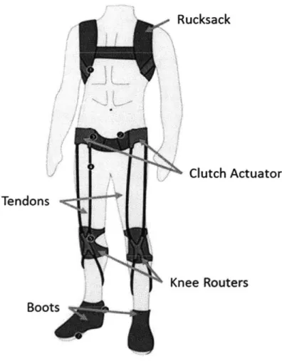
The exotendon suit was designed to be flexible and lightweight, as to not impede the movement of the wearer, the eventual goal being to be worn underneath the wearer's own clothes. Very few rigid components were involved. As the suit is intended for military use, it is designed to be
work with combat boots and a rucksack. In addition to the boots and rucksack, the wearer dons clutch actuators, mounted to a belt, and flexible knee wraps, as shown in Figure 2.1.
Polypropylene webbing is used as a tendon, spanning the wearer's legs from the clutches to the boots, routed through the knee wraps.
Rucksack
Clutch Actuators
Tendons
Knee Routers
Boots
Using sensors placed within the boots, a microcontroller mounted within the rucksack selectively activates the clutches as the wearer walks to create tension on the tendon, and apply torques to the knee and ankle joint. The wiring and control is further explained in Chapter 2.7.
2.2 Tendon Routing and Knee Joint
The torque applied to the knee by the tension in the tendons varies depending on the tendon routing. The distance from the center of the knee joint that the tendon passes is the radius, and as the radial distance from the center of the knee joint increases, a greater torque is applied to the knee. Two configurations were tested, the full radius of the knee (Figure 2.2a) and a radius of zero (Figure 2.2b).
a)
b)
r=R
r=O
Users determined that a torque applied at the full radius of the knee, as in Figure 2.2a was uncomfortable and felt unnatural. A radius of zero was used during the experiments. This zero radius was achieved by sewing sleeves for the tendon on a flexible neoprene knee wrap, as
shown in Figure 2.3. The sleeves are sufficiently wide enough to allow the tendon to slide freely along the length of the leg, but do not shift much radially, keeping the tendons at a radius of zero.
Figure 2.3 Sleeves were sown into a neoprene knee wrap to allow the tendons to slide.
The knee wrap is adjustable to allow for wearers of different sizes. Plastic fittings along the tendons allowed for the length of the tendons to be adjusted for the height of the wearer. The tendons interface with the clutches through the use of buckles, so the suit can be easily donned and doffed.
2.3 Clutch Design
The function of the clutch in the exotendon suit is to selectively apply tension to the tendons traversing the user's legs. While the clutch is not activated, the tendon needs to be free to extend under tension, and otherwise retract and when activated, the clutch needs to brake and lock the tendon. A clock-spring design, similar to that of a tape measure, was implemented in order to allow for the tendon to retract. Electro-permanent magnets and electro-magnets were both considered as actuation methods for the clutch.
2.3.1 Electro-Permanent Magnet
An electro-permanent magnet (EPM) is made up of a magnet with a high coercivity and a magnet core with a low coercivity, encased in a coil and a steel shell as shown in Figure 2.4. In the case proposed, Neodynium-Iron-Boron (NIB) and Aluminum-Nickel-Cobalt (Alnico) were to be used as magnets of high and low coercivity, respectively. The NIB and Alnico magnets are aligned in parallel and a coil is wound around them. When a pulse of current is applied to the coils, the magnetic field created is great enough to switch the magnetization direction of the Alnico magnet, but not of the NIB magnet due to its higher coercivity.
Alnico
NIB
Coil
Steel
Figure 2.4 A cross section of an EPM. A copper coil is wound around an Alnico and NIB magnet core. Steel comprises the shell.
Figure 2.5 illustrates the two states of the EPM. The EPM is in the on state when the two magnets and their fluxes are aligned within the EPM. The magnetic flux then travels through an adjacent ferromagnetic surface and the surface is attracted to the magnet. The EPM is in the off state when the two magnets and their fluxes are oppositely aligned. In this case, the magnetic flux circulates with the EPM and not through an adjacent ferromagnetic surface."
ON
OFF
Figure 2.5 The on and off states of an EPM. A pulse of current through a coil can reverse the polarization of the Alnico magnet, changing the state of the EPM.
While the EPM is in either state, power is not consumed. Power is only consumed during the transition period between states when a pulse of current is used to switch the polarity of the Alnico magnet. For this reason, EPMs have the potential for being a very low powered solution for many applications. However, the frequency at which the EPMs would need to switch state for application in human walking is too high for efficient use. Applying a pulse of current
through the coil great enough to change the polarity of the Alnico magnet involves the charging and discharging of a large capacitor. Designing a circuit to charge and discharge a large
capacitor at the frequency required for human walking was out of the scope of this thesis. For this reason, an electro-magnet clutch was prototyped.
2.3.2 Electro-Magnet Clutch
In an electro-magnet, a sustained current through a coil magnetizes an iron core, attracting a ferromagnetic surface. Unlike an EPM, an electro-magnet consumes power while in the on state. The first clutch prototypes were designed and fabricated using the off-the-shelf rotary
electro-magnet clutch shown in Figure 2.6.
Figure 2.6 The OTS rotary electro-magnet clutch used in the first prototyped clutches. Specifications are included
in the Appendix.'"
These OTS electro-magnet clutches have a holding torque of 9 Nm and use about 8 W of power. Power-On clutches were selected to ensure safety for the user. In the case of a broken
2.4 Clock-Spring
The clock-spring was designed to support the weight of the tendon, estimated to be about I kg, as to be able to keep the tendon taut while the clutch is not activated. The torque, T, delivered by a clock-spring can be calculated with the equation:
88B8f 45,23 Equation 2.1
where E is the Young's modulus of the spring, b is the width of the material, t is the material thickness, 89s the desired angular rotation in revolutions, and L is the length of material,
illustrated in Figure 2.7. Using 0.35 mm thick and 12.7 mm wide spring steel, and a full rotation, the length of material required to provide a torque to support 1 kg at a 20 mm radius was about
200 mm. A cross-section of the clutch with the fabricated clock-spring is shown in section 2.5 in Figure 2.9.
Ot
moo.
2.5 Full Clutch Design
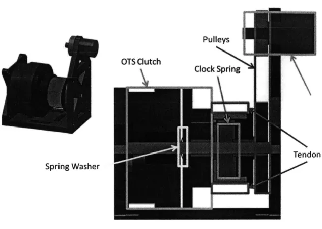
The OTS electro-magnet clutch used consists of two components, a stationary component housing the coil, and a mating rotational part shown in Figure 2.8 in red and blue respectively. In order for the clutch to work as intended, the inner radius of the clock-spring needs to be rigidly attached to the stationary component of the OTS electro-magnet clutch, while the outer radius of the clock-spring needs to be rigidly attached to the mating rotational part. This way, as the mating part rotates, the clock-spring works to restore it to an original position.
This was accomplished by rigidly attaching the stationary component of the OTS electro-magnet clutch and an aluminum shaft (yellow in Figure 2.8) to a base plate to ensure that the shaft and clutch are stationary relative to each other. The mating clutch component is a mounted on the shaft via a sleeve bearing, allowing the mating component to rotate relative to the shaft and stationary component. A sheath was 3D-printed to mount to the mating component, shown as pink in Figure 2.8. The clock-spring is installed within the sheath (space outlined in light blue in Figure 2.8), with the inner radius attached to the aluminum shaft, and the outer radius attached to the 3D-printed sheath. The tendon is then wrapped around outside of the sheath. A spring washer is included on the aluminum shaft in between the stationary and rotational components of the OTS electro-magnet clutch. This spring washer is strong enough to keep the two components separated when the clutch is off for minimum friction, but weak enough to be compressed when the clutch is on and allow for the normal force between the two components to create a large holding torque.
Spring Washer
Figure 2.8 Cross-section of OTS clutch unit. The stationary component of the OTS clutch is shown in red, and the mating rotational component is shown in blue.
While the clutch is off, when the tendon is pulled and extended, the sheath and rotational mating component rotate relative to the stationary component and aluminum shaft. When the tendon is released, the clock-spring returns to its original position, retracting the extended tendon.
Activating the clutch locks the rotational mating component and tendon wherever they are. Pulleys are used to translate the rotation of the mating component to a potentiometer, which could be used to measure the extension of the tendon. The fabricated prototype and clock-spring are shown in Figure 2.9.
Figure 2.9 Close up image of the fabricated OTS clutch unit, and a cross-section showing the clock spring within.
2.6 Electro-Magnet Cone-Clutch Prototype
A second design and prototype for an electro-magnet clutch was attempted. The purpose of this prototype was to create a smaller electro-magnetic clutch than the OTS electro-magnet clutch through the use of a cone-clutch geometry. The interaction of a cup and cone in a cone-clutch yields a greater holding torque than the interaction of two plates for the same normal force. A cone-clutch diagram and its variables are shown in Figure 2.10.
D FN
Figure 2.10 Schematic of a cone-clutch and the cup (left) and cone (right) interaction.
The holding torque, T, created by a cone-clutch is determined with the following expression 14:
8888
. .
. Equation 2.2where p is the coefficient of friction, FN is the normal force between the cup and cone, D is the outer diameter of the cone, d is the inner diameter of the cone, and Bs the angle of the cone.
In this design, the cone is the electro-magnet and the cup is the mating ferromagnetic surface. The normal force within the cone-clutch is created by the electro-magnet. Finite Element Method Magnetics (FEMM) was used to design the electro magnet. Figure 2.11 shows the FEMM analysis of the proposed electro-magnet. The force the electro-magnetic cone applies on the cup is about 245 N, which translates to a holding torque of about 4.25 Nm.
Axis
Cup
Coil
Cone
Cross Sectional View
1.342e+000: >1.412&+000 1.271*000 : 1.342e+000 12000+000: 1.271e+000 1.130e4000 1.2000+000 10590+000: L130e+000 9.896e-001 : .05904000 9.1800-01 9.8860-001 4.4740-01 : 9.1800-001 7.76860W: &4740-001 7M02*-001 : 7.76ft-001 63560-001: 7.062*-00 5.650&-001 6.356.-001 4.943&-001 5.650e-001 4.2370-001 :4.943e-001 3.S31*001 :4.237*-001 2.825e-001 : 3.531.401 2.119e-001 : 2.825t-001 1413.-001 : 2119e-001 7.065e002 : L4130-001 <3.161e-C : 7.0650-002
Oonfy Plot: li. Too&
R
=21.75mm
Figure 2.11 FEMM of cross section of designed electro-magnet. The normal force in this model is about 245 N,
which yields a holding torque of about 4.25 Nm.
The design of the clutch unit is similar to that of the OTS electro-magnet clutch and is shown in Figure 2.12. The cone (red) and axis (yellow) are stationary, and the cup and sheath (blue and cyan) are allowed to rotate. The clock-spring within the sheath applies a restorative force on the cup sheath. When the electro-magnet is operated, the cup and sheath can no longer rotate and are locked.
50mm
Pulleys and belt Clock Spring (not pictured)
67mm
Figure 2.12 Cross-section of electro-magnet cone-clutch unit. The stationary component of the clutch is shown in red, and the mating rotational component is shown in blue.
A fabricated electro-magnet cone-clutch is shown in Figure 2.13 and a fabricated cone-clutch unit is shown in Figure 2.14.
Figure 2.13 Fabricated electro-magnet cone-clutch. The electro-magnetic cone is on the left, and the mating cup is on the right.
Figure 2.14 Assembled cone-clutch unit. When pulled, the tendon unwraps, but when the tension is removed, the tendon is retracted.
Testing of the electro-magnet cone-clutch yielded a holding torque of about 1 Nm, a quarter of the expected 4.25 Nm. The holding torque achieved in a cone clutch is highly dependent on the
surface finish of the mating surfaces. Due to the manufacturing process (turning the surfaces on a manual lathe), the mating surfaces were not smooth enough to ensure the proper contact. Future prototypes could be improved by turning the components on a CNC lathe.
2.7 Wiring and Control
Footswitches from B & L Engineering (Figure 2.15) are used within the combat boots to sense when a food is bearing weight. Each footswitch has 4 sensors built in, a sensor at the heel, at the 1s' and 5,h metatarsals, and at the toes, to allow for distinction in weight distribution.
Figure 2.15 Footswitches from B & L Engineering. Footswitches have sensors at the heel, I' and 5th metatarsal,
and toes. The connectors used are 5-pin LEMO connectors.'5
Another researcher in the lab designed and assembled a control box for use with the exotendon suit, shown in Figure 2.16. The box houses an mbed microcontroller and an XBee wireless antenna. The controller is written and transmitted to the microcontroller via the terminal
emulator Tera Term. Feedback from the footswitches is used to control the timing of the clutch.
The controller is powered by a 9 V battery, and the clutches are powered by two 12 V LiPo batteries.
2.8 Full Suit
Due to the poor results of the electro-magnet cone-clutch, the OTS electro-magnet clutch was used during experimental tests with subjects. The full suit and testing setup are shown on a subject in Figure 2.17. The subject is wearing all of the components of the exo-suit, including the rucksack and COSMED system, discussed in Chapter 3.
COSMED System
Webbing d
Treadmill
==== Clutches
.. Soft Knee Brace
3 Experimental Design and Results
Testing of the exotendon suit on a Bertec Fully Instrumented Treadmill (Bertec FIT) was accomplished at the Wyss Institute for Biologically Inspired Engineering's Motion Capture Laboratory (Figure 3.1). Five novice subjects performed, wearing a pair of military combat boots and carrying a standard issue MOLLE rucksack (Modular Lightweight Load-carrying Equipment) with a 20 kg load, both shown in Figure 3.2. Testing for each subject followed similar protocols, and metabolic power data and surface electromyograms (sEMG) were
collected during testing with a COSMED K4b2 system and a Delsys Trigno system, respectively.
6wIf
Figure 3.1 Bertec FIT treadmill used for the experiments. A safety harness is attached to the rucksack during testing, and an emergency stop button is at hand for the subject, should he or she ever feel uncomfortable.
Figure 3.2 An example of a military combat boot and MOLLE pack used by each subject during experimental testing.
3.1 Protocol
The subjects ranged in age from 23-28, with a mean height of 176.2 cm and a mean weight of 73.3 kg. Every trial was performed at a treadmill speed of 1.25 m/s. Each subject participated in
six trials: two trials in street clothes; two trials with the exosuit donned but unpowered; and two trials with the exosuit donned and powered.
A sample protocol followed is shown in Table 3.1. Every subject's first and last trials were
done in street clothes. Ideally, metabolic power measurements of the identical first and last trials should be similar. If the measurements are not similar, all of the metabolic power measurements need to be adjusted. Subjects wear athletic shorts, combat boots, and carry the rucksack during these two trials.
The exosuit is worn during the four middle trials. These trials are any combination of two active suit trials, and two passive suit trials. Each trial is about 8 minutes long, separated by 5 minute rest periods.
Table 3.1 A sample protocol used during subject testing at the Wyss Institute
Time
Trial Test Condition (minutes)
1 Street Clothes 8 Rest 5 2 Passive Exosuit 8 Rest 5 3 Active Exosuit 8 Rest 5 4 Active Exosuit 8 Rest 5 5 Passive Exosuit 8 Rest 5 6 Street Clothes 8
Figure 3.3 Front view of subject participating in the experiment.
3.2 Collection and Analysis of Metabolic Power Data
A COSMED K4b2 system (Figure 3.5) is used in every trial to measure pulmonary gas
exchange. This portable metabolic measurement system is worn by the subject. A mask covers the subject's nose and mouth and a harness is worn to carry the portable system.
K4 b
2
Figure 3.5 Portable COSMED K4b2 system and mask worn by subjects during experimental testing.'6
Energy expenditure can be estimated with the COSMED K4b2 system by measuring pulmonary gas exchange. In particular, V02 and VCO2 measurements are considered. V02 and VCO2 refer to the rate at which one inhales oxygen and exhales carbon dioxide, respectively. During load carriage, the volume of oxygen and carbon dioxide exchanged increases and plateaus, as shown in Figure 3.6.
V02 and VCO2
2000 1800 1600 1200-E 4 1000- ---IE -+V02 800--v2 200 04 0:00:00 0:0126 0:02:53 0:04:19 005:46 0:07:12 0:08:38 Time (h~rmas) 0:06:00 0:08:00Figure 3.6 V02 and VCO2 measurements of a subject during load carriage, taken over a trial about 8 minutes long. The average values of V02 and VCO2 are taken from a 2 minute segment between the 6 h and 8*' minute for
metabolic power calculations.
Subject trials are 8 minutes to allow for V02 and VCO2 measurements to plateau. A 2 minute segment of the plateau is averaged and used to calculate metabolic power. For a trial, the metabolic power is calculated using the following equation, 7
. .. .. . - , Equation 3.1
where V02 and VCO2 are the average V02 and VCO2 measurements over a time period t.
Results and Discussion
To compare results between subjects, the metabolic power is normalized with the subjects' weights, and repeated trials were averaged. A summary of the results is shown in Table 3.2 and Figure 3.7.
Table 3.2 Metabolic power, normalized by weight, for the three conditions tested.
Metabolic Power (W/kg) % Increase from
Street Passive to Active
Subject Clothes Passive Active Conditions
1 N/A 5.90 6.09 3.34 2 6.92 7.34 7.11 -3.13 3 6.80 6.75 6.85 1.42 4 5.63 5.98 5.68 -5.06 5 6.81 7.41 7.11 -4.07
Metabolic Power
* Street Clothes * Passive a Active 1 2 3 Subject 4 5Figure 3.7 Metabolic power, normalized by weight, for the three conditions tested.
The results of these tests do not show a significant effect of activating the exosuit. Metabolic power results from trials where the suit was powered were within ±5% of the results from trials where the suit was worn but unpowered. No clear trend is visible. However, only 5 tests were executed. More subjects and more trials could possible allow a trend to be seen if there is one.
3.3 Collection and Analysis of Electromyography
Surface electromyogram (sEMG) data was collected during testing with a Delsys Trigno system. Four sEMG sensors were used on one of each subjects' legs to measure the muscle activation of the gastrocnemius lateralis, tibialis anterior, bicep femoris, and vastus medialis muscles.
Placement of the sensors is shown in Figure 3.8.
Vastus Medialis Bicep Femoris
Gastrocnemius Tibialis Anterior
Lateralis
Figure 3.8 Placement of sEMG sensors on a subject's leg.
The sEMG sensors measure the electrical signals that muscles output during activation. For best results, the skin on which the sensors are placed should be shaved and cleaned, removing dead skin cells. This yields a lower skin impedance at the points of contact of the electrodes. In this study, none of the participants opted to have their legs shaved. Figure 3.9 shows a sample raw EMG recording taken of the gastrocnemius lateralis during this study.
Raw EMG of Gastrocnemius Lateralis
0.5 0.4 0.3 0.2 0.1 Time 0 -0.1 -0.2 -0.3 -0.4Figure 3.9 Raw EMG data gathered from a sEMG sensor on the gastrocnemius lateralis.
Due to the large amount of noise in the raw measurement data, in order to make comparisons between different trials, the data is normalized and rectified. Because of the random nature of EMG signals, the data must be digitally smoothed once the data is normalized and rectified. The
most common method of smoothing is by a root mean square (RMS) smoothing algorithm, which is used in this study.'8 The RMS smoothing is achieved by calculating the square root of the mean of the sum of squares of a specified envelope around each point:,,
For most EMG application, an envelope of 20 - 500 ms is used.'9 For this study, an envelope of 150 ms was used. Figure 3.10 shows a portion of the data from Figure 3.9 normalized and rectified in blue, and the result of the smoothing algorithm in red.
Processed EMG of Gastrocnremius Lateralis
0.2 0.16-0.14 - -0.12 -Normalized and .1 -Rectified EMG oos -RMS Smooth 0.06 -Averaging 0.04 0.02 - - --0 L.a. LT ime
Figure 3.10 Processed EMG data gathered from a sEMG sensor on the gastrocnemius lateralis. First, the data is normalized and rectified (blue), then it is smoothed using a RMS smooth averaging algorithm.
The amplitude mean is used to quantitatively compare the EMG measurements of different trials for the same muscle. The means are calculated during the time periods of muscle activation, as shown in Figure 3.11. In this study, the calculated means for a two minute period of the trial (between minutes 6 and 8, as during metabolic power calculations) are averaged and compared.
0.14 0.12 0.1 0.08 cc 0.06 0m 0.04 0.02 0
Mean of Smoothed EMG of Gastronemious Lateralls
I--RMS Smooth Av r n
WO a
in EMG
Figure 3.11 Processed EMG data gathered from a sEMG sensor on the gastrocnemius lateralis is shown in red. The mean voltage amplitudes for muscle activations are shown in green.
Results and Discussion
EMG measurements between different muscles and different subjects are not easily compared, so
only relative measurements between passive and active conditions are compared in this study. A summary of the results is shown in Tables 3.3 - 3.6 and Figures 3.12 - 3.15.
Mei
Time
Table 3.3 Mean EMG values for gastrocnemius lateralis muscles, for the three conditions tested.
E
CO
Mean EMG (mV) % Increase from
Street Passive to Active
Subject Clothes Passive Active Conditions
1 N/A 59.0 59.2 0.364 2 46.8 47.9 48.8 1.71 3 93.3 93.3 77.7 -16.7 4 40.3 44.0 42.2 -4.20 5 78.5 75.8 68.5 -9.70 2 83 Z
8n3
JI Js J aIs.Ell' F
't BEE BEIE -80M] 88 -88 2 78 2Table 3.4 Mean EMG results for tibialis anterior muscles, for the three conditions tested. The sEMG sensor used on Subject 1 for the tibialis anterior measurements experienced excessive noise that could not be isolated. The data
from this sensor was not used in the calculations for the results.
Mean EMG (mV) % Increase from
Street Passive to Active
Subject Clothes Passive Active Conditions
I N/A N/A N/A N/A
2 56.7 64.4 59.5 -7.69 3 54.7 53.3 52.2 -1.97 4 53.5 54.9 59.4 8.21 5 93.7 82.7 95.3 15.4
J88~
I oam 8W9 -c 88 88 U -1-1-~
2 78112Figure 3.13 EMG values for the tibialis anterior muscles, for the three conditions tested. The sEMG sensor used on
Subject I for the tibialis anterior measurements experienced excessive noise that could not be isolated. The data from this sensor was not used in the calculations for the results.
Table 3.5 Mean EMG results for bicep fe moris
Mean EMG (mV) % Increase from
Street Passive to Active
Subject Clothes Passive Active Conditions
1 N/A 48.1 42.7 -11.4 2 26.7 27.3 25.8 -5.59 3 28.6 26.1 25.8 -1.06 4 39.0 39.4 37.9 -3.85 5 82.0 75.7 80.9 6.81 ~ -. '2~32 Mb C= BE 8W1 80
I
_________________________________________ _______________________________________I-_______________________________
______________________________ L RRIll
II
2 78 1 ,fFigure 3.14 EMG values for the bicep femoris muscles, for the three conditions tested.
Eat.
p
? U-
1-~
Table 3.6 Mean EMG results for vastus medialis muscles, for the three conditions tested. The sEMG sensor used on Subject 3 for the vastus medialis measurements experienced excessive noise that could not be isolated. The data
from this sensor was not used in the calculations for the results.
Mean EMG (mV) % Increase from
Street Passive to Active
Subject Clothes Passive Active Conditions
1 N/A 33.6 35.6 6.04
2 43.8 44.1 38.6 -12.6
3 N/A N/A N/A N/A
4 46.4 45.1 44.4 -1.56 5 57.8 54.4 53.3 -1.94
8
Z
J08
8ffle-h.kw
*.E~* ~ ? - U 88BB i 88-88 2 78 12 ,Figure 3.15 EMG values for the vastus medialis muscles, for the three conditions tested. The sEMG sensor used on Subject 3 for the vastus medialis measurements experienced excessive noise that could not be isolated. The data from this sensor was not used in the calculations for the results.
The results of these tests are highly variable and do not show a significant effect in activation of the exosuit. Half of the mean EMG amplitude results from trials where the suit was powered were within ±5% of the results from trials where the suit was worn but unpowered. An
additional 5 of the 18 sets had powered systems within ±10%, while the remaining 4 results are within ±17%. The results are both positive and negative, with no visible trend.
The sEMG sensor placement was not ideal in many cases, which had an effect on the results obtained. For some subjects, the sensors on the upper leg would be brushed by the subject's athletic shorts. This phenomenon made the results from the vastus medialis sEMG sensor on Subject 3 unusable, and may have also skewed the other results. In addition, none of the subjects opted to shave patches of their legs to allow for better conductivity between the sEMG electrodes and the subjects' muscles, so the results were not of the best quality. These factors, and other possible noise sources, are likely the cause for the highly variable results obtained for the EMG portion of the experiment.
4 Conclusions and Future Work
The goal of this thesis was the design, development, and evaluation of a lightweight, exotendon suit for load carriage.
A simple exotendon suit architecture was designed and implemented, consisting of two knee
braces, a length of polypropylene tendon, a belt, two electro-magnet clutches, and a control box. The knee radius of the tendon routing was optimized for comfort during testing and off-the-shelf knee braces were modified for a radius of zero. The soft architecture allows the user to move freely, as it does not impede the wearer's natural motions. Two actuation strategies were
considered, EPMs and electro-magnets. EPM clutches were dismissed due to complicated power electronics. Two pairs of electro-magnet clutches were designed and prototyped (OTS clutch and cone-clutch). The OTS electro-magnet clutches were used during experimental testing due to their higher holding torques.
Metabolic power testing and EMG data collecting was performed at the Wyss Institute Motion Capture Lab on five subjects for three different conditions: street clothes, exosuit worn but unpowered, and exosuit worn and powered. Results of the tests were inconclusive. There was no significant evidence that powering the exosuit has a positive or negative effect on the wearer s energy usage.
In order to determine the effect the exotendon suit has on human walking, more testing needs to be performed. In this round of experiments, five subjects were used. Another round of
experiments with double the subjects would more likely highlight a trend. Another consideration to take into account while designing further experiments is the effect of learning on human energy expenditure. In the study of their exoskeleton, Sawicki and Ferris determined that the
metabolic energy usage measured decreased in users over three sessions on three different days. 0 This implies that for best results, the subjects should train in at least two sessions before taking data.
The major result of this thesis is the development of a platform and protocol for future experiments. Current exoskeleton research involving actuators at the ankle have not been successful in reducing metabolic energy due to the additional weight to the ankle. More effort is being put into systems where the actuators are located closer to the torso, minimizing the weight at the extremities. Wehner shows some promising results with their exosuit, with metabolic power of the active suit as low as metabolic power used walking without the suit.20 The future of exoskeletons is headed towards light, flexible, low-power systems, and this thesis is working towards these new ideals.
References
1Kazerooni,
H., Stegar, R., "The Berkeley lower extremity exoskeleton (BLEEX)." J. Dyn. Syst.Meas. Control-Trans. ASME, 128, 2006.
2 Low, K. H., Liu, X. P., Goh, C. H., Yu, H. Y., "Locomotive control of a wearable lower exoskeleton for walking enhancement." J. Vib. Control 12, 2006.
3 Ferris, D. P., Gordon, K. E., Sawicki, G. S., Peethambaran, A., "An improved powered
ankle-foot orthosis using proportional myolectric control." Gait & Posture, Vol. 23, 2006. 4 Pratt, J. E., Krupp, B. T., Morse, C. J., Collins, S. H., "The RoboKnee: An exoskeleton for
enhancing strength and endurance during walking." IEEE Int. Conf Robotics and
Automation, New Orleans, LA, (IEEE Press) 2004.
5 Ferris, D. P., Sawicki, G. S., Daley, M. A., "A Physiologist's perspective on robotic
exoskeletons for human locomotion." Int. J. Humanoid Robotics, Vol. 4, No. 3, 2007. Norris, J. A., Granata, K. P., Mitros, M. R., Byrne, E. M., Marsh, A. P., "Effect of augmented
plantarflexion power on preferred walking speed and economy in young and older adults." Gait & Posture, Vol 25, Issue 4, April 2007.
7 Sawicki, G. S., Ferris, D. P., "Mechanics and energetics of level walking with powered ankle exoskeletons." The Journal of experimental biology, Vol. 211, May 2008.
Lenzi, T., Zanotto, D., Stegall, P., Carrozza, S. K., Agrawal, M. C., "Reducing Muscle Effort in Walking through Powered Exoskeletons." Proceedings of the 34th Annual International
Conference of the IEEE EMBS, San Diego, California. 28 August - 1 September, 2012. 9 Browning, R. C., Modica, J. R., Kram, R. Goswami, A., "The effects of adding mass to the legs
on the energetics and biomechanics of walking." Med. Sci. Sports Exerc. Vol. 39, 2007.
10 Sawicki, G. S., Ferris, D. P., "Powered ankle exoskeletons reveal the metabolic cost of plantar flexor mechanical work during walking with longer steps at constant step frequency."
The Journal of experimental biology, Vol. 212, January 2009.
Knaian, A. N., "Electropermanent Magnetic Connectors and Actuators: Devices and Their Application in Programmable Matter." Diss. Massachusetts Institute of Technology, Cambridge, 2010.
12 "Flanged Mounted Power-On Brakes." Stock Drive Products/Sterling Instruments. 2013. 1 August, 2013. sdp-si.com.
4 Shigley, Joseph and Charles Mischke. Mechanical Engineering Design. 6th ed. Boston: McGraw Hill, 2001.
15 "Footswitches." B & L Engineering. 2013. www.bleng.com.
16 "Cardiopulmonary Exercise Testing." COSMED Pulmonary Function Equipment. 2013. www.cosmedusa.com.
17 Brockway, J. M., "Derivation of formulae used to calculate energy expenditure in man." Hum.
Nutr. Clin. Nutr., Vol. 41, No. 6, 1987.
18 Basmajian, J. V., De Luca, C. J., "Muscles Alive: Their Function Revealed by Electromyography." Williams Wilkins, Baltimore 1985.
Konrad, P., "The ABC of EMG: A Practical Introduction to Kinesiological Electromyography." Noraxon EMG & Sensor Systems. 2005.
20 Wehner, M., Quinlivan, B., Aubin, P. M., Martinez-Villalpando, E., Baumann, M., Stirling, L.,
Holt, K., Wood, R., "A Lightweight Soft Exosuit for Gait Assistance." IEEE
International Conference on Robotics and Automation (ICRA), Karlsruhe, Germany, May
Appendix
OT *TMp
N. ~
Clutch Product Finder
Power-On Flange-Mounted Brakes
ik 0,. Pustis~terIUmg Is.tvuin..t N Ph...; 8164-" U fa 64M40"
8 24VOLTS DC U ANTIBACKLAS WHEN ENERGIEU U ZERO DRAG WHEN DE-ENERGIZED
12 in Mik ~ E SQ OG 4 THRU HOLES EQ. SP ON A OC B.C. KO917AD4 OBF9-22*A1 *BF9-30A12 E:Oher ohl caltosque af OP OA 15 179.5 x 10- 2900
I-Z 1.vo 1.%3 1 AM 1 UD 1 ...Li±.4 Z
1.78 2436 2.13 187 182 .06 .75 127 .5
E.2 2.873 250 .166 233 .06 . - 1.74
263 3.499 3.13 187 263 .06 1.06 1.84 12
3.27 4-186 .M 187 325 .09 1.75 1.93 3
gs avadable on specia oder. w bumnieig; urs shiped bumshed.
*1For Catalog Nunbers: -11A04, ini" woinwg air gap at knsation shaM be .0041009.
-17AO4-22A06, -26A6, -26AD, inia wo aing Wgap at isation sha be .006.013.
-30A10, 3GAI 2, Vmnt woddng an gap at instion sha be.00lW.018.
I&W* be dscombied when present sock is depieed.
F/
0
e
.25) W 7 .500 .625 .5.5+64 .837
.094 .1 l .188
mbed
NXP LPC1768
prototyping board
This board, which works with the groundbreaking mbed tool suite -lets you create a functioning prototype faster than ever. The tightly coupled combination of hardware and software makes it easy to explore designs quickly, so you can be more adventurous, more inventive, and more productive.
Features
* Convenient forn-factor- 40-Opn DIP, 0.1-inch pitch
0 Drag-and-drop proamng, with the board represented as a USS drive
a Best-in-:ass Cotex-M3 haidware
-100 Ml ARM with 64 KB of SRAM,512 KB of Rash
- Ethernet, US8 OTG
* SPI, PC. UART CAN
- GPIO. PWM, ADC, DAC
0 Easy-to-Use online tools
- Web-based CIC+-+ prograrring environment
- Uses the ARM RealView compile engine
- AP-driven development using libraries with intuitive
intefaces,
- Comprehensive help and online community
Benefits
o Get started right away, with nothing to install
0 Get working fast, using high-level APIs
k Explore, test, and demonstrate ideas more effectively
o Write dean, compact code that's easy to modify
I, Log in from anywhere, on Windows, Mac or Linux
The mbed NXP LPCI768 board lets you create prototypes
without havwng to wori with low-level mecrocontroller details,
so you can experiment and iterate faster than ever
Designers compose and compile embedded software using a browser-based IDE. then download it quicidy and easily, using a simple drag-and-drop function, to the board's
NXP Cortex-M3 microcontroller LPC1768.
Engineers new to embedded applications can use the board to prototype real products incorporating microcontrollers, while experienced engineers can use it to be more productive
in early stages of development The mbed tools are designed
to let you try out new ideas quickly, in much the same way that an architect uses a pencit and paper to sketch out concepts before tumning to an advanced CAD program to implement a design.
Egegnt simpkity
The mbed tool has been designed for the best trade-off between versatility and immediate connectivity. The LPC1768. housed in an LQFP package, is mounted on the mbed board, which uses a 40-pin DIP with a 01-inch pitchTe cmvenient form factor works seanlessly with solderiess breadboaids, stripboards, and PCBs.
There is no software to install - everything, even the compiler.
is onine. The compiler and libraries are completely modular, so
they're easy to use, yet powerful enough to take on complex,
real-world
applications-Atocitd agram of md AP LPCI6 board
Hassle-fre. startup
Getting started is as simple as using a USB Flash drive. Simply connect the mbed NXP LPC1 768 board to a Windows. Mac or Linux computer and it will appear as a USS drive. Follow the link on the board to connect to the rnbed website. where you can sign up and begin designing. There are no drivers to install or setup programs to run. It's so easy, in fact, that you can have a *Helo World!* program running in as little as five minutes.
Onmm. compiler
The rmbed Compier lets you write programs in C++ and then compile and download them to run on the mbed NXP LPC1 768
microcontroller. There's no need to run an install or setup program, since the compiler runs online. Supported browsers include Intemet Explorer, Firefox, Safari, or Chrome running on a Windows, Mac, or Linux PC. You can log in from anywhere and simply pick up where you left off. And, since you're working with a web-based tool, you can be confident that it's
already configured and will stay up-to-date.
The compiler uses the ARM RealView compile engine, so it produces clean, efficient code that can be used
free-of-charge, even in production. Existing ARM application code and middleware can be ported to the LPC1768
microcontrozer, and the nbed tools can be used alongside other professional production4eve tlas, such as Keil MDK.
r .s~ P~.~reM T ~ Aoa~niutw~uaiw ± ~hcbmriw ± ~ NgIOwgio
I
I I 1~ii i'~iiThe med Cmier
Priphral braries
The mbed Library provides an API-driven approach to coding that eliminates much of the low-level work normally associated with MCU code development. You develop code using meaningful peripheral abstractions and API calls that are intuitive and already tested. That frees you up to experiment, without worrying about the vmplementation of the MCU core or its peripherals. You can work faster and be more creative,
and can concentrate on exploring and testing the options for your design.
Rather than simply providing examples. mbed focuses on reusable library functionality, with dear interfaces and solid implementations The core mbed Library supports the main
LPC1768 peripherals, and the libraries already contributed by the mbed design community include USS, TCP/IR and HTTP
support. It's also possible to add third-party and open-source stacks.
The libraries comply with the ARM EAB1 and are built on the Cortex Microcontroller Software Interface Standard (CMSIS),
Iammsn msow Daok 0943 U Sww ioln
SPI
don SPI pbk mA SPdr %t uwt Sr lostane wd Ale, W a
Th on aak e or r ebsmmoe.and s d
J/ 5end a tyte to a SPI Slave, a
SFn aeme iS, 5, 'a /1 uos, mx
atespce dev e~wiae II
makng it possible to migrate to Other tokhaiM or lmplement cusom co for peripheal intraces
LPC1?6taumwentu~
The NmP covntoler famiy PCTx .s sute. of cost-effectw, ko-pow CortwM3 devc *at operate
t p to 100 MHz They feature best-on-dasspenphera support, inuding Ethemet, USS 20host/OTGdevice, and CAN 2.oB There are 512 KB of r-ash memory and 64 KB of SRAM. The architecture uses a rult4ayer AAB bus that a#ows highbandwidth peripherals uch as Ethernet and USS to run siklanewSly, wtthoat invacing peoa The family is pi-conpable w NXP's 100-pin LPC236 series of ARM-based mikocontrolers.
The mbbdour
UP ID 64 KB
SRAM IUpto512KB FLAW I DebugTe I
I
Trace Corex-M3 core I Nested CPU PLL VicBrown Out Detect
MPU
I ~ Muk4ayer AHB MatrixI
IEhernet MACI DMA
US= HotTGjl EIPLL JA GP DMAJ
3 x I2C 3 x 2 4.* UARTS 2 x
FM+ SSPPI RS485/DA#Aodem CAN2.08
Advanced Penphel Buis
12-bi S<h 10-bit 4 x32-t Mo uad Encoder
ADC DAC TF er Con01 PW" fied
Lbt. U307"Wm*&*7m