HAL Id: hal-02344548
https://hal.archives-ouvertes.fr/hal-02344548
Submitted on 17 Mar 2020HAL is a multi-disciplinary open access archive for the deposit and dissemination of sci-entific research documents, whether they are pub-lished or not. The documents may come from teaching and research institutions in France or abroad, or from public or private research centers.
L’archive ouverte pluridisciplinaire HAL, est destinée au dépôt et à la diffusion de documents scientifiques de niveau recherche, publiés ou non, émanant des établissements d’enseignement et de recherche français ou étrangers, des laboratoires publics ou privés.
RF Coils for Preclinical Multinuclear Imaging Based on
Coupled-wire Structures Working in Resonant and
Non-resonant Regime
Tania S. Vergara Gomez, Marc Dubois, Stanislav Glybovski, Benoit Larrat,
Julien de Rosny, Carsten Rockstuhl, Monique Bernard, Redha Abdeddaim,
Stefan Enoch, F. Kober
To cite this version:
Tania S. Vergara Gomez, Marc Dubois, Stanislav Glybovski, Benoit Larrat, Julien de Rosny, et al.. RF Coils for Preclinical Multinuclear Imaging Based on Coupled-wire Structures Working in Resonant and Non-resonant Regime. PhotonIcs & Electromagnetics Research Symposium, Jun 2019, Rome, Italy. pp.771-778, �10.1109/PIERS-Spring46901.2019.9017435�. �hal-02344548�
RF COILS FOR PRECLINICAL MULTINUCLEAR IMAGING BASED
ON COUPLED-WIRE STRUCTURES WORKING IN RESONANT AND
NON-RESONANT REGIME
Tania S. Vergara Gomez1,2*, tania-del-socorro.VERGARA-GOMEZ@etu.univ-amu.fr ; Marc Dubois1, marc.dubois@fresnel.fr;
Stanislav Glybovski3, s.glybovski@metalab.ifmo.ru; Benoit Larrat4, benoit.larrat@cea.fr;
Julien de Rosny5, julienderosnyatespci@gmail.com; Carsten Rockstuhl6,7, carsten.rockstuhl@kit.edu; Monique Bernard2, monique.bernard@univ-amu.fr; Redha Abdeddaim1, redha.abdeddaim@fresnel.fr; Stefan Enoch1, stefan.enoch@fresnel.fr;
Frank Kober2, frank.kober@univ-amu.fr;
1Aix Marseille Univ, CNRS, Centrale Marseille, Institut Fresnel, Marseille, France 2Aix Marseille Univ, CNRS, CRMBM, Marseille, France
3Department of Nanophotonics and Metamaterials, ITMO University, St. Petersburg, Russia 4CEA, NeuroSpin, Université Paris Saclay, Gif-sur-Yvette, France
5ESPCI Paris, PSL Research University, CNRS, Institut Langevin, Paris, France
6Institute of Theoretical Solid State Physics, Karlsruhe Institute of Technology, Karlsruhe, Germany 7Institute of Nanotechnology, Karlsruhe Institute of Technology, Karlsruhe, Germany
Corresponding author: Tania S. Vergara Gomez, CRMBM,
Aix Marseille Université
27 Boulevard Jean Moulin, 13385 Marseille, France
tania-del-socorro.VERGARA-GOMEZ@etu.univ-amu.fr
Funding: European Union’s Horizon 2020 Research and Innovation programme under Grant Agreement No 736937, France Life Imaging National Programme grant ANR-11-INBS-0006 and the Ministry of Education and Science of the Russian Federation (project No. 14.587.21.0041 with the unique identifier RFMEFI58717X0041).
ABSTRACT
Passive inductive metamaterials have been explored as alternative radio frequency (RF) coils for magnetic resonance imaging (MRI) with the aim to control and optimize the imaged volume and the sensitivity independently. Nevertheless, such structures result in a low signal-to-noise ratio (SNR) since the contribution of the loop in the global performance of the coil is reduced. Therefore, the purpose of this work is to explore a new strategy by combining off-resonance metamaterials with a resonant surface coil and observe the advantages that can be obtained. An elementary structure consisting of two parallel off-resonance wires coupled with a resonant surface coil was numerically analyzed. For experimental characterization, a prototype was built and tested in a 7 T MRI scanner for proton (1H) and fluorine (19F) using a phantom. In addition, other coil setups were tested for reference and comparison in terms of B1+ magnetic field homogeneity, signal and noise. The results show that with this new strategy a conventional surface coil can be optimized in terms of sensitive volume while maintaining its high SNR. Metamaterials permit a customized adjustment of volume and sensitivity in addition to the simple adaptation to other nuclei, making them beneficial elements in the design of RF coils.
KEYWORDS
B1+ maps, 19F MRI, computational electromagnetics, metamaterials, RF coil engineering, SNR
INTRODUCTION
Two common categories of radio frequency (RF) coils are predominant in magnetic resonance imaging (MRI), volume and surface coils. Surface coils present high sensitivity, which results in a high signal-to-noise ratio (SNR) [1]. The main disadvantage of surface coil is their small sensitive volume since the B1+ magnetic field decays as function of the loop radius and loop plane distance [2]. In contrast, volume coils, such as birdcage coils [3-4], present a large and homogeneous B1+ magnetic field, but with a reduced sensitivity [5].
Earlier works based on metamaterials aimed to bring more flexibility on this trade-off by attempting to control the sensitive volume and the SNR independently [6-8]. These configurations were based on coupled-wire arrays and relied on the hybridization mechanism [9]. The wires were either of a resonant length [9] or miniaturized using high permittivity materials [10] or capacitive interconnections [11]. All resonant structures were inductively powered by a feed loop, accomplishing a good compromise between SNR and volume. However, a high sensitivity like the one presented by a small surface coil [12] was not achieved.
The aim of this work is to explore quantitatively whether advantages are reachable by using a metamaterial in a non-resonant regime alternatively to a resonant regime. For this purpose, we designed, simulated and built an elementary structure consisting of two adjustable parallel wires [13]. Such structure was able to switch from a resonant to a non-resonant regime. The hypothesis behind this work is that coupled-wire structures can be used off-resonance and be combined with a
commercial surface coils, achieving high sensitivity and large imaging volume. To validate such hypothesis, B1+ maps of the proposed structure were numerically and experimentally obtained and compared. Additionally, 1H SNR maps and 19F images were acquired and analyzed.
MATERIALS AND METHODS
Numerical analysis
B1+ maps of four different coil configurations (Figure 1) were numerically analyzed using CST Microwave Studio 2017 (Computer Simulation Technology GmbH, Darmstadt, Germany). The maps were normalized to 1 W accepted power.
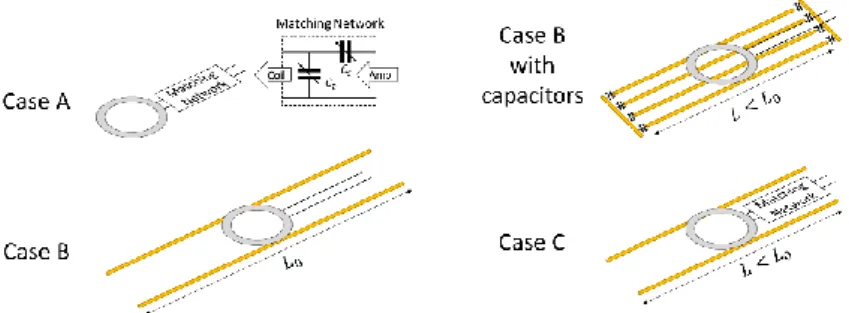
Case A: surface coil with two lumped elements as matching network. Case B: resonant coupled-wire structure with two coupled-wires of length L0 coupled to a non-matching feed loop. Case B with capacitors: resonant coupled-wire structure with four wires of length L capacitive interconnected and coupled to a non-matching feed loop. Case C: off-resonance coupled-wire structure with two wires of length L combined with a matched loop.
The loops used for cases A, B and C had a diameter of 3 cm. For case B with capacitors, a 2 cm diameter loop was used. In cases B and C, the wires were parallel and 3 cm apart while the loop was placed 1 mm above the wires. In case B with capacitors, the wires had a gap of 1 cm between them. The material used for all metallic parts was copper. All simulations were carried out using a frequency of 300 MHz (1H Larmor frequency at 7 T) and an input power of 1 W, in the presence of a homogeneous phantom of 35x35x70 mm3 with a relative dielectric permittivity (ε) of 50 and a conductivity (σ) of 0.98 S/m. The RF shield was simulated as a copper tube of 1000 mm length and 100 mm internal diameter.
FIGURE 1: Sketch of the four configurations numerically analyzed.
The tuning and the impedance matching of case A was achieved using the lumped elements of the matching circuit. In case B, the matching was obtained by placing the loop close to the wires (1 mm separation) while the tuning was reached by adjusting the wires to a length of L0, close to a half wavelength (≈50 cm). The matching of case B with capacitors was done similarly to case B. For the tuning, the capacitors were fixed to 7 pF and fine tuning was completed by adjusting the wires to length L (6 cm).
Case C required that both, surface coil and coupled-wire structure were off-resonance to correctly tune the assembled coil at 300 MHz. To detune the coupled-wire structure a length L < L0 was used
(39 cm). This configuration will be named “non-resonant regime” as the wires resonance is shifted to higher frequencies compared with the Larmor frequency. In opposition, we will refer to “resonant regime” when the resonance frequency of the wires is the same as the Larmor frequency.
Coils setups
Two coupled-wire structure prototypes were built using telescopic brass tubes [14] to allow an adjustable length to alternate between resonant and non-resonant regimes. Each structure was placed on a plastic board of 2 mm thickness for easy handling. The first coupled-wire structure was a long resonator consisting of two open wires separated by 3 cm. The second coupled-wire structure was a miniaturized resonator of four wires separated by 1 cm. Resonance of this miniaturized structure was achieved by placing a capacitor (ATC 100 E Series, American Technical Ceramics, Huntington Station, NY) of 6.8 pF at the ends of each wire.
The four different configurations were assembled. Case A: a 30 mm diameter commercial surface coil (Bruker 1H-19F, model 1P T957 8V). Case B: the long resonant coupled-wire structure combined with a printed feed loop of 3 cm diameter. Case B with capacitors: the miniaturized resonant coupled-wire structure combined with a printed feed loop of 2 cm diameter. Case C: an open non-resonant coupled-wire structure combined with a commercial surface coil (Bruker 1H-19F, model 1P T957 8V).
For length optimization in cases B and B with capacitors, on-bench measurements were conducted on a vector network analyzer (VNA MS2036C, Anritsu, Kanagawa, Japan) with and without load.
MRI experiments
In order to validate the numerical studies, the different coils were tested in a PharmaScan 7 T MR system (Bruker Biospin, Ettlingen Germany) running ParaVision 6.0.1 using a 2-2-trifluoroethanol phantom of 35x35x90 mm3. The phantom was placed horizontally at the center of each coil, parallel to the MRI bore axis.
The different coils were compared as single channel transmit-receive antennas for proton and fluorine imaging. As an additional reference, a 70 mm diameter commercial 1H birdcage coil (Bruker Biospin) was included in the experiments.
A fast low-angle shot (FLASH) localizer sequence was run after wobble, iterative shimming, frequency and power adjustment. B1+ maps in coronal and sagittal orientations were obtained using the actual flip angle imaging (AFI) [15-17] sequence (echo time (TE) / repetition time (TR) / TR2 = 4 / 20 / 100 ms, flip angle (α) = 55°, matrix of 128x128x8, field of view (FOV) = 9x9 cm2, coronal slab of 26 mm and sagittal slab of 35 mm). The maps were calculated using MATLAB (MathWorks, Natick, MA, USA).
The 1H images were obtained using a 2D FLASH (TE / TR = 2.54 / 500 ms, α = 60°, slice thickness = 0.9 mm, in-plane spatial resolution = 0.7x0.7 mm2, FOV = 9x9 cm2). The obtained signal was processed with MATLAB to calculate the SNR maps as the ratio of each pixel over the noise
standard deviation of the image. SNR profiles were calculated from these maps.
The 19F images were acquired using a T2-TurboRARE-3D sequence (TE/TR = 68.22/3000 ms, rapid imaging with refocused echoes (RARE) factor = 32, slice thickness = 40 mm, in-plane spatial resolution = 1x1 mm2, FOV = 6x6 cm2) and processed in MATLAB to overlay them on top of the 1H FLASH images using a transparency of 0.6, from a scale of 0 to 1.
RESULTS
Numerical Study
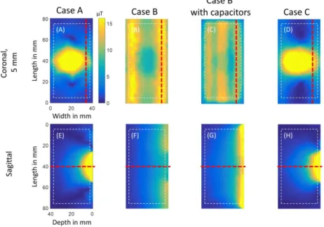
Figure 2 shows the simulated B1+ maps in coronal and sagittal orientations. It can be seen that in case A, the B1+ field is concentrated at the center of the phantom. In contrast, cases B and B with capacitors present a more homogeneous distribution of the field along the phantom. Case C presents a combination of the field distributions from cases A and B.
FIGURE 2: Simulated B1+ maps presenting coronal (5 mm depth inside the phantom close to the coils) and sagittal slices. White dash lines locate the edges of the phantom. Red bold dash lines locate the profile cuts. (A),(E) case A; (B),(F) case B; (C),(G) case B with capacitors and (D),(H) case C.
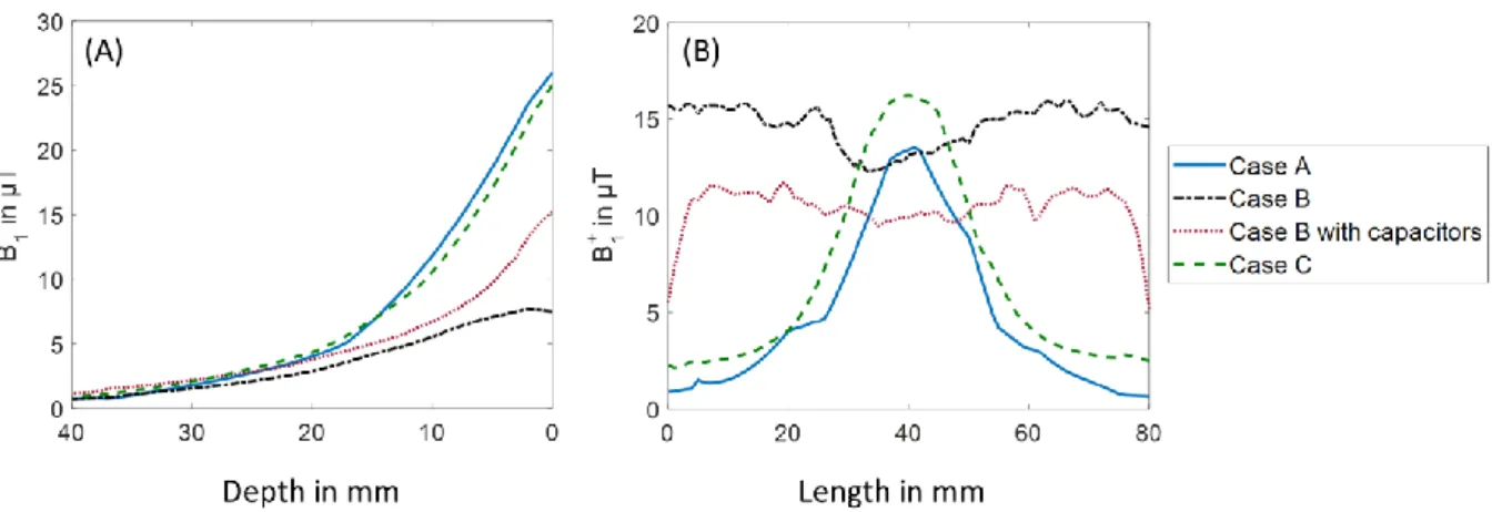
Figure 3 presents the B1+ profiles obtained from the maps in Figure 2 for a more quantitative analysis. As expected, case A holds the maximum B1+ magnitude (Figure 3A). Nonetheless, this high sensitivity is only present at the position of the coil. As we move away from the coil, the magnitude decreases, as it can be observed in Figure 3B, where the profile was taken at the right edge of the phantom from the coronal slice. In contrast, cases B and B with capacitors present a lower B1+ magnitude at the center, case B having the lowest one (Figure 3A). However, their sensitivity extends along the whole phantom (Figure 3B). This can be linked to the currents flowing inside the loop and the wires in each case [18]. Case C seems to maintain a high B1+ magnitude (25 µT), similar to case A (26 µT), in addition to a horizontal extension of the field.
FIGURE 3: Simulated B1+ profiles of the phantom with the different coil configurations. (A) shows the profiles obtained at the center of the sagittal slices. (B) shows the profiles obtained from the right side of the coronal slices.
Coils setups
With no load, the optimal length of the long resonant coupled-wire structure in case B was 49.5 cm for 1H at 300 MHz and 52.2 cm for 19F at 282.6 MHz. A reduction of 5 mm was necessary to compensate the frequency shift produced by loading the antenna with a phantom. For the miniaturized resonant coupled-wire structure in case B with capacitors, the optimal length with load was 7.7 cm for proton and 8.7 cm for fluorine. In case C the coupled-wire structure was fixed to 39.0 cm for both nuclei and the tuning and impedance matching was achieved using the matching circuit of the surface coil.
MRI experiments
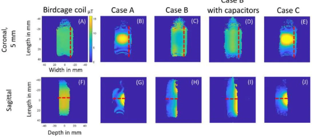
Figures 4 and 5 present the B1+ and SNR maps obtained from the phantom. The results of the experimental B1+ maps show similar distribution of the field as the ones obtained through simulation. In case C, the contribution of both wires and surface coil become evident since it presents an extension of the sensitive volume while maintaining a high B1+ magnitude (29 µT), similar to the B1+ magnitude presented by the surface coil alone (Figure 6A,B).
Figure 6C,D presents the SNR profiles. In SNR terms, the highest magnitudes are presented by cases A and C. The large volume and low SNR is given by cases B and B with capacitors. The birdcage coil, as expected, presented a very homogeneous distribution of the B1+ field in all directions and a low SNR followed by case B.
FIGURE 4: Experimental B1+ maps presenting coronal (5 mm depth inside the phantom close to the coils) and sagittal slices (dash lines locate the profile cuts). (A),(F) birdcage coil; (B),(G) case A; (C),(H) case B; (D),(I) case B with capacitors and (E),(J) case C.
FIGURE 5: Phantom SNR maps showing coronal (5 mm depth from the edge of the phantom close to the coils) and
FIGURE 6: Top: experimental B1+ profiles of the phantom with the different coil configurations. Bottom: 1H SNR maps of the different configurations. (A),(C) show the profiles obtained at the center of the sagittal slices. (B),(D) show the profiles obtained from the right side of the coronal slices.
The SNR maps shown in Figure 5 and the fluorine images in Figure 7 demonstrate that the distribution of signal remains similar regardless of the nuclei used. SNR calculations were not performed for fluorine since the images present low spatial resolution due to the weak nuclei concentration, which results in noisy images.
The SNR maps present more homogenized results compared to the B1+ maps, since they benefit from a localized partial saturation due to the FLASH sequence [19]. The standard deviation of noise can be found on top of each SNR map. It can be seen that it does not have great variations between coils, making it possible to compare them in terms of signal and noise.
FIGURE 7:19F T2-turboRARE-3D sagittal images in jet color map acquired with: (A) case B; (B) case A; (C) case B with capacitors; (D) case C. Due to the different sensitivities, the color scale is modified between map (A) and maps (B-D). The images were overlaid on top of 1H FLASH images in gray scale.
DISCUSSION AND CONCLUSION
This study presents a comparison between different configurations of coupled-wire structures and conventional volume and surface coils. Here, we have demonstrated that in one coil, it is possible to benefit from the high sensitivity offered by a surface coil and the sensitive volume extension given by a coupled-wire structure. However, a simple combination of the two resonant structures is not possible due to the strong mutual coupling [12]. This phenomenon results in the splitting of the resonant mode, creating two hybrid resonances that are shifted away from the desired Larmor frequency [20-21]. Therefore, we proposed an elementary structure conformed by two parallel adjustable wires in order to easily switch between resonant and non-resonant regimes.
Our elementary structure was numerically analyzed in both resonant and non-resonant regimes (cases B and C) along with a simple matched loop. A second structure consisting on four miniaturized resonant coupled wires was analyzed as additional reference (case B with capacitors).
It has been shown recently that the distribution of currents within the components of the coil plays an important role in the resulting B1+ field distribution [18]. A matched loop presents higher current amplitude compared to a feed loop, therefore the B1+ magnitude in case A is high but localized, compared to cases B and B with capacitors, where the B1+ field is more homogeneous as shown in the simulations (Figures 2 and 3).
To validate the numerical results and study the properties of the coupled-wire structures when used in a resonant and non-resonant regime, the experimental coils were assembled and tested as single transmit-receive antennas for proton and fluorine in a 7 T preclinical MR scanner using a phantom.
The experimental B1+ results obtained in Figures 4 and 6A,B can be compared to the ones obtained numerically in Figures 2 and 3. As expected, cases B and B with capacitors had a more homogeneous B1+ magnitude field (Figure 4A,F) compared to case A (Figure 4B,G). Case C (Figures 4E,J) preserves the high B1+ magnitude coming from the surface coil, while presenting a wider B1+ volume. This difference becomes clear in the SNR maps and profiles of Figures 5 and 6C,D, showing how the coupled-wire structures can change the SNR and the sensitive volume depending on the regime they are working on.
The 19F results (Figures 7) demonstrated that cases B, B with capacitors and C present enough sensitivity to perform 19F images even though the fluorine had a weak concentration. It can be seen that the coils presented the same distribution of signal as they did for proton imaging.
In conclusion, we studied the resonant and non-resonant regimes of a coupled-wire structure and the results demonstrate that the chosen regime affects the magnitude and spatial distribution of the B1+ magnetic field and the resulting SNR. Phantom experiments confirmed the obtained numerical predictions, showing that by using a coupled-wire structure in the non-resonant regime, the sensitive volume of a commercial surface coil can be improved without losing its high sensitivity, as presented in case C. It was further demonstrated that, despite the working regime, coupled-wire structures provide sufficient SNR to obtained 19F images and that the Larmor frequency difference does not
affect their performance. Structures based on coupled wires can be used as flexible and complementary elements in the design of versatile RF coils that aim to optimize the conventional trade-off between high SNR and imaged volume.
R E F E R E N C E S
[1] Keltner J, Carlson J, Roos M, Wong S, Wong T, Budinger T. Electromagnetic fields of surface coil in vivo
NMR at high frequencies. Magn Reason Med. 1991;22:467‐480.
[2] Hoult D. The NMR receiver: a description and analysis of design. Prog Nucl Magn Reson Spectrosc.
1978;12:41‐77.
[3] Hayes CE, Edelstein WA, Schenck JF, Mueller OM, Eash M. An efficient, highly homogeneous
radiofrequency coil for whole‐body NMR imaging at 1.5 T. J Magn Reson Imaging. 1985;63:622‐628.
[4] Tropp J. The theory of the bird‐cage resonator. J Magn Reson Imaging. 1989;82:51‐62.
[5] Doty FD, Entzminger G, Kulkarni J, Pamarthy K, Staab JP. Radio frequency coil technology for small‐
animal MRI. NMR Biomed. 2007;20:304‐325.
[6] Jouvaud C, Abdeddaim R, Larrat B, De Rosny J. Volume coil based on hybridized resonators for magnetic
resonance imaging. Appl Phys Lett. 2016;108:023503.
[7] Hurshkainen A, Nikulin A, Georget E, et al. A novel metamaterial‐inspired RF‐coil for preclinical dual‐
nuclei MRI. Sci Rep. 2018;8:9190.
[8] Zubkov M, Hurshkainen AA, Brui EA, et al. Small‐animal, whole‐body imaging with metamaterial‐
inspired RF coil. NMR Biomed. 2018;31:e3952.
[9] Dubois M, Leroi L, Raolison Z, et al. Kerker Effect in Ultrahigh‐Field Magnetic Resonance Imaging. Phys
Rev X. 2018;8:031083.
[10] Shchelokova AV, Slobozhanyuk AP, Melchakova IV, et al. Locally enhanced image quality with tunable
hybrid metasurfaces. Phys Rev Appl. 2018;9:014020.
[11] Glybovski SB, Shchelokova AV, Kozachenko AV, et al. Capacitively‐loaded metasurfaces and their
application in magnetic resonance imaging. In: Radio and Antenna Days of the Indian Ocean (RADIO). Piscataway, NJ: IEEE; 2015:1‐2.
[12] Mispelter J, Lupu M, Briguet A. NMR probeheads for biophysical and biomedical experiments:
theoretical principles & practical guidelines. London, UK: Imperial College Press; 2006.
[13] Glybovski SB, Tretyakov SA, Belov PA, Kivshar YS, Simovski CR. Metasurfaces: From microwaves to
visible. Phys Rep. 2016;634:1‐72.
[14] Shchelokova AV, van den Berg CAT, Dobrykh DA, et al. Volumetric wireless coil based on periodically
coupled split loop resonators for clinical wrist imaging. Magn Reson Med. 2018;80:1726‐1737.
[15] Yarnykh VL, Actual flip-angle imaging in the pulsed steady state: a method for rapid three-dimensional
mapping of the transmitted radiofrequency field, Magnetic Resonance in Medicine. 2007;57:192-200.
[16] Nehrke K, On the steady-state properties of actual flip angle imaging (AFI), Magnetic Resonance in
Medicine. 2009; 61:84-92.
[17] Nikulin A, de Rosny J, Haliot K, Larrat B, Ourir A, Opencage radio frequency coil for magnetic resonance
imaging, Appl Phys Lett. 2019;114:053503.
[18] Vergara Gomez TS, Dubois M, Glybovski SB, et al. Wireless coils based on resonant and nonresonant
coupled‐wire structure for small animal multinuclear imaging. NMR Biomed. 2019;e4079
[19] Haase A, Frahm J, Matthaei KD, FLASH imaging: rapid NMR imaging using low flip angle pulses. J
Magn Reson 1986;67:258-266.
[20] Orfanidis SJ. Electromagnetic waves and antennas. New Brunswick, NJ: Rutgers University; 2002. [21] Mett RR, Sidabras JW, Hyde JS. MRI surface‐coil pair with strong inductive coupling. Rev Sci Instrum.