Publisher’s version / Version de l'éditeur:
Canadian Consulting Engineer, 41, December 7, p. 56, 58, 2000-12-01
READ THESE TERMS AND CONDITIONS CAREFULLY BEFORE USING THIS WEBSITE.
https://nrc-publications.canada.ca/eng/copyright
Vous avez des questions? Nous pouvons vous aider. Pour communiquer directement avec un auteur, consultez la première page de la revue dans laquelle son article a été publié afin de trouver ses coordonnées. Si vous n’arrivez pas à les repérer, communiquez avec nous à [email protected].
Questions? Contact the NRC Publications Archive team at
[email protected]. If you wish to email the authors directly, please see the first page of the publication for their contact information.
NRC Publications Archive
Archives des publications du CNRC
This publication could be one of several versions: author’s original, accepted manuscript or the publisher’s version. / La version de cette publication peut être l’une des suivantes : la version prépublication de l’auteur, la version acceptée du manuscrit ou la version de l’éditeur.
Access and use of this website and the material on it are subject to the Terms and Conditions set forth at
Prone to fail
Makar, J. M.
https://publications-cnrc.canada.ca/fra/droits
L’accès à ce site Web et l’utilisation de son contenu sont assujettis aux conditions présentées dans le site LISEZ CES CONDITIONS ATTENTIVEMENT AVANT D’UTILISER CE SITE WEB.
NRC Publications Record / Notice d'Archives des publications de CNRC:
https://nrc-publications.canada.ca/eng/view/object/?id=546c5ebc-b5dc-496b-b4f3-81c66ef3356b https://publications-cnrc.canada.ca/fra/voir/objet/?id=546c5ebc-b5dc-496b-b4f3-81c66ef3356b
Prone to fail
Makar, J. M.
A version of this paper is published in / Une version de ce document se trouve dans : Canadian Consulting Engineer, v. 41, no. 7, Dec. 2000, pp. 56, 58
www.nrc.ca/irc/ircpubs
Prone to Failure
Jon Makar, Ph.D., P. Eng. Institute for Research in ConstructionNational Research Council Canada 1500 Montreal Road, Ottawa, Ontario K1A 0R6
The water industry faces unique problems in operating their water pipeline systems. In most branches of engineering, a single structural failure is a matter for grave concern. In a water distribution system, such problems are a matter of course, with some larger cities experiencing three hundred or more failures a year of small diameter (150 – 300 mm) mains. Water utilities attempt to manage this damage in order to minimize their total costs, rather than to prevent the failures entirely.
This response is driven by the consequences of the small diameter failures. Their cost of repair is significantly cheaper than the corresponding cost of replacement or rehabilitation. It is only when multiple failures occur (or are predicted to occur) within a single kilometer of pipe that it becomes economically reasonable to replace those pipes. Secondly, the commodity transported in water pipes is environmentally benign compared to other commodities such as oil and natural gas. Damage can be done by the force of the water flowing from the break, but a failed water pipe will not pollute the surrounding environment, burn or explode. As a result, although preventative measures such as cathodic protection or remote field inspection can be used to reduce the risk of failure, simply repairing the breaks and choosing the most cost effective time to replace the line may be the best response for dealing with deteriorating water distribution systems.
The situation changes when large diameter (450 mm+) transmission line pipes fail. These failures are rare, but the consequences of a failure become so high that the
water utility is better off in taking strong proactive preventative measures. Transmission mains are vital lifelines for the cities they supply, providing an essential service. In addition, the damage produced by a large diameter main failure in a downtown core can run into millions of dollars and has the potential to inflict difficult to measure social costs. The recent failure of a large diameter gray cast iron main in Boston produced over US $10 million in damage when it flooded the basement of the city’s main public library and damaged a collection of historical documents.
Although a single small diameter failure is inconsequential in comparison with a transmission main break, the total cost to repair such failures over the course of a year can be substantial. The National Research Council Canada (NRC) has therefore investigated failures in both transmission and distribution systems and particularly in gray cast iron pipes. Gray cast iron is the most common piping material in most North American cities and generally the most prone to failure. This study has resulted in a clearer understanding of the causes of pipe failures and the development of best practice guidelines for conducting of failure analysis on gray cast iron pipes.
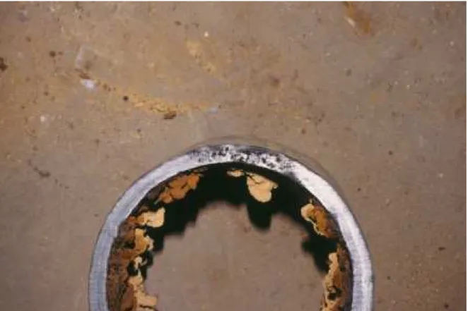
Corrosion is well known in the industry as a problem for all diameters of gray cast iron pipes (Figure 1), with failures due to corrosion penetrating the pipe wall becoming more common as the diameter of the pipe increases. In addition to the pipes that fail directly due to corrosion penetrating the pipe wall, approximately 90% of the other failures examined by NRC were associated with corrosion pits or graphitisation (graphitisation is the term for the corrosion process where the iron is leached out of the pipe, leaving behind a weak graphite flake matrix and the appearance of an intact pipe).
Another significant cause of failures is casting defects. They often take the form of air pockets left in the metal of the pipe after it was cast (Figure 2), but they can be inclusions in the pipe metal, changes in pipe wall thickness, or the results of poor heat treatment. Both corrosion and casting defects will cause structural weakening of the pipe, leading to failure under design loading conditions. Some failures can also be caused when the pipe has experienced forces greater than those anticipated in the pipeline’s design.
These causes and the environmental forces that act on pipes produce a number of different mechanical failure modes in addition to corrosion penetration. Typically around 80% of small diameter pipes (300 mm or less) fail in bending by circumferential cracking (Figure 3). Tensile failure due to ground forces and bell splitting may also occur. Medium diameter pipes (450 mm – 500 mm) sometimes fail by spiral splitting, with an initial circumferential crack that then moves down and around the length of the pipe. Larger pipes (600 mm or more) will often fail by longitudinal splitting or the shearing off of a bell section of the pipe.
When these failure processes have been considered in the past, it has been assumed that pipes fail in a single episode. However, recent work by NRC has indicated that many circumferential failures and at least some bell splits occur as multiple events, with the pipe cracking part way through and then stopping, leaving the pipe wall still partially intact. One or more subsequent cracking incidents will then take place before the pipe fails completely. The pipe may even be identified and removed from service before that final damage occurs (Figure 3). This work means that refinements may be possible to non-destructive evaluation techniques such as leak detection or remote field
eddy current inspection to improve the chances of finding partially intact pipes and repairing them before a complete failure has taken place. It has also provided new information to help decipher the full failure process for these pipes.
A second part of NRC’s work on failure analysis has involved examining past failure analyses by consultants and water utilities. This review has suggested that clear, broadly accepted procedures need to be developed to ensure that accurate and comprehensive failure analyses are carried out after a large diameter main failure. Some past work has missed essential parts of the analysis process, either because certain tests were not being performed or because incomplete samples were delivered to the consultants who were conducting the analysis. In addition, some utilities appear to have assumed after reading the results of a failure analysis that, since the material of their pipe was shown to be in good condition and without corrosion, no further work was required beyond pipe replacement. However, in this case, the forces applied to the pipe clearly exceeded its designed structural capacity to resist them. A strengthened pipeline or work to remove the forces that caused the failure may be needed to prevent future problems.
NRC is developing failure analysis guidance for this type of water pipe. This work will include guidelines decisions that should be made before a failure has taken place (which pipe failures warrant a full failure analysis, who should do the work, what type of expertise needs to be available), the on-site work as the failure is repaired (types of information to be recorded, the use of cameras and video tapes, types of samples to be taken), the laboratory tests that should be performed, and the decisions that need to be made at the end of the process. These guidelines are intended to allow water utilities and consulting engineers to utilise the knowledge NRC has acquired about the failure process
to make better decisions about their pipe systems. More information about the guidelines can be obtained by contacting Dr. Jon Makar at the NRC’s Institute for Research in Construction (613-993-3797 – [email protected]) or by visiting the NRC’s failure analysis web site: http://www.nrc.ca/irc/uir/bu/condition/failure.html
Figures:
Figure 1 Corrosion penetration of the pipe wall in a 150 mm pipe. All photographs are of pipes from the City of Toronto that were delivered to the University of Toronto for mechanical testing after they had failed.
Figure 2 A region of air pockets along the edge of a 150 mm pipe. The black colouring is due to the oxidation of the metal by the trapped air during the casting process.
Figure 3 Circumferential failure in a 150 mm pipe. The gray metal along the fracture surface shows where the pipe wall was still intact before removal from the ground. The square pattern on the pipe was produced by a repair clamp.