Abstract—This paper puts forward an approach for boosting the efficiency of energy management strategies (EMSs) in fuel cell hybrid electric vehicles (FCHEVs) using an online systemic management of the fuel cell system (FCS). Unlike other similar works which solely determine the requested current from the FCS, this work capitalizes on simultaneous regulation of current and temperature, which have different dynamic behavior. In this regard, firstly, an online systemic management scheme is developed to guarantee the supply of the requested power from the stack with the highest efficiency. This scheme is based on an updatable 3D map which relates the requested power from the stack to its optimal temperature and current. Secondly, two different EMSs are used to distribute the power between the FCS and battery. The EMSs’ constraints are constantly updated by the online model to embrace the stack performance drifts owing to degradation and operating conditions variation. Finally, the effect of integrating the developed online systemic management into the EMSs’ design is experimentally scrutinized under two standard driving cycles and indicated that up to 3.7% efficiency enhancement can be reached by employing such a systemic approach. Moreover, FCS health adaptation unawareness can increase the hydrogen consumption up to 6.6%.
Index Terms—Online parameter estimation, optimal energy management strategy, proton exchange membrane fuel cell, systemic management, thermal control.
NOMENCLATURE
𝑃̂𝐹𝐶 fuel cell estimated power (W)
𝑇̂𝐹𝐶 fuel cell estimated stable temperature (°C) 𝑛̇𝑐𝑜𝑛𝑠
𝑂2 consumed oxygen in the reaction (mol/s)
𝑛̇𝑖𝑛𝑂2 supplied oxygen to PEMFC (mol/s)
∆𝑃𝐹𝑎𝑙𝑙,𝑘 negative PEMFC power change (W) ∆𝑃𝑅𝑖𝑠𝑒 positive PEMFC power change (W)
This work was supported in part by the Natural Sciences and Engineering Research Council of Canada (NSERC), the Fonds de recherche du Québec – Nature et technologies (FRQNT), and Canada Research Chairs program.
M. Kandidayeni, A. Macias, and L. Boulon are with the Hydrogen Research Institute, Department of Electrical and Computer Engineering, Université du Québec à Trois-Rivières, QC G8Z 4M3,
Canada (email: [email protected],
[email protected], and [email protected]). S. Kelouwani is with the Hydrogen Research Institute, Department of Mechanical Engineering, Université du Québec à Trois-Rivières, QC G9A 5H7, Canada (e-mail: [email protected]).
𝐶𝑂2 oxygen concentration (mol/cm3) 𝐶𝑏𝑎𝑡 battery capacity (Ah)
𝐷𝐶𝐹𝑎𝑛 cooling fan duty cycle 𝐸𝑁𝑒𝑟𝑛𝑠𝑡 reversible cell potential (V) 𝐼𝐹𝐶 fuel cell current (A)
𝐼𝑉𝑎𝑙𝑣𝑒 current of the Hydrogen valve (A) 𝐼𝑏𝑎𝑡 battery current (A)
𝐼𝑚𝑎𝑥 fuel cell maximum current (A)
𝑀𝐴𝑃𝐸𝑃𝐹𝐶 fuel cell power mean absolute percentage error
𝑀𝑎𝑖𝑟 air molar mass (kg/mol) 𝑁𝑐𝑒𝑙𝑙 number of cells
𝑃𝐵𝑎𝑡 battery power (W) 𝑃𝐹𝐶 fuel cell stack power (W) 𝑃𝐹𝐶−𝑆𝑦𝑠 PEMFC system power (W)
𝑃𝐹𝑎𝑛 consumed power by cooling fan (W) 𝑃𝐻2 hydrogen pressure in anode side (Pa) 𝑃𝑂2 oxygen partial pressure in cathode side (Pa) 𝑃𝑉𝑎𝑙𝑣𝑒 consumed power by hydrogen valve (W) 𝑃𝑏𝑎𝑡 battery pack power (W)
𝑃𝑟𝑒𝑞 requested power (W) 𝑄𝑎𝑖𝑟 air flow (m3/s)
𝑅𝑀𝑆𝐸𝑇𝐹𝐶 stack temperature root-mean-square error
𝑅𝑏𝑎𝑡−𝑐ℎ internal resistance during charging (Ω) 𝑅𝑏𝑎𝑡−𝑑𝑐ℎ internal resistance during discharging (Ω) 𝑅𝑖𝑛𝑡𝑒𝑟𝑛𝑎𝑙 fuel cell internal resistor (Ω)
𝑆𝑂2 oxygen stoichiometry
𝑆𝑙𝑒𝑤𝑟𝑎𝑡𝑒,𝑓𝑎𝑙𝑙 falling dynamic limitation (W/s) 𝑆𝑙𝑒𝑤𝑟𝑎𝑡𝑒,𝑟𝑖𝑠𝑒 rising dynamic limitation (W/s) 𝑇𝐹𝐶 stack temperature (°C)
𝑇𝐹𝐶 stack temperature (°C) 𝑇𝑎𝑚𝑏 ambient temperature (°C) 𝑈𝑏𝑎𝑡−𝑂𝐶 open circuit voltage (V) 𝑈𝑏𝑢𝑠 bus voltage (V)
𝑉𝐹𝐶 stack voltage (V)
𝑉𝑉𝑎𝑙𝑣𝑒 voltage of the Hydrogen valve (V) 𝑉𝑎𝑐𝑡 activation loss (V) 𝑉𝑐𝑜𝑛 concentration loss (V) 𝑉𝑜ℎ𝑚𝑖𝑐 ohmic loss (V) 𝑎𝑛 fitting parameters (𝑛 = 1,2,3) 𝑐n empirical coefficients (𝑛 = 1 … 3) 𝑓𝐻2 hydrogen flow (SLPM) 𝑝𝑛 fitting parameters (𝑛 = 1 … 6) 𝑡0 initial step time (s)
𝑡𝑓 final step time (s)
𝛼𝑛 fitting parameters (𝑛 = 0,1,2)
Mohsen Kandidayeni, Student Member, IEEE, Alvaro Macias, Student Member, IEEE,
Loïc Boulon, Senior Member, IEEE, and Sousso Kelouwani, Senior Member, IEEE
Efficiency Upgrade of Hybrid Fuel Cell
Vehicles’ Energy Management Strategies by
𝜁𝑛 parametric coefficients (𝑛 = 1 … 3) 𝜂𝐷𝐶−𝐷𝐶 DC-DC converter efficiency 𝜂𝐹𝐶−𝑆𝑦𝑠 efficiency of the PEMFC system 𝜉𝑛 semi-empirical coefficients (𝑛 = 1 … 4) 𝜌𝑎𝑖𝑟 air density (kg/m3)
Δ𝑡 time interval (s) 𝐵 parametric coefficient 𝐶𝑉𝐸 cross-validation error 𝐹 Faraday constant (sA/mol)
𝐿𝐻𝑉 hydrogen low heating value (J/mol) 𝑁 number of data points
𝑆𝑂𝐶 state of charge
𝑡 total time of driving cycle (s) I. INTRODUCTION
A. Literature survey
UEL cell hybrid electric vehicles (FCHEVs) normally employ a proton exchange membrane (PEM) fuel cell (FC) stack, as the main power source, and a battery pack or/and a supercapacitor (SC), as the secondary power source [1]. The specific characteristics of each source, in terms of power delivery and efficiency, make the design of an energy management strategy (EMS) vital for having an efficient power distribution [2]. The existing EMSs in the literature can be divided into three categories of rule-based, optimization-based, and intelligent-based [3]. Several strategies based on these categories and their combinations are available in the literature. In [4], a multi-mode fuzzy logic controller (FLC) is used to perform the power distribution in a FCHEV. The modes of the FLC are determined by a multi-layer perceptron neural network using the historical velocity window, and the rule base is optimized by a genetic algorithm. This strategy has improved the fuel economy by 8.89%, compared to a single-mode FLC. In [5], a multi-state (i.e., coasting, braking, and station parking) equivalent consumption minimization strategy (ECMS) is formulated by quadratic programming (QP) for a tram. This EMS has led to 2.5% energy consumption decline compared to a rule-based power following EMS. In [6], a convex optimization is proposed to minimize the energy cost by optimizing the control decisions and the cost of power sources. This study shows that appropriate estimation of the PEMFC rated power can decrease the hydrogen cost up to 61%. In [7], a heuristic method called bounded load following strategy (BLFS) is suggested for a FC-battery vehicle. The PEMFC power is bounded between two limits according to the efficiency curve of the stack. The boundaries of this strategy are refined with respect to the optimal trajectory obtained by dynamic programming. In [8], the suggested strategy has two phases of optimal policy generation for a long trip, using a distribution optimization algorithm, and revising the EMS considering the actual traffic conditions in short-term time steps. In [9], an adaptive controller based on tuning the FLC parameters for different loads is proposed. The authors state that the PEMFC voltage declines after a while due to degradation. Under this condition, the rule-based values should be reconsidered.
B. Necessity of online mapping
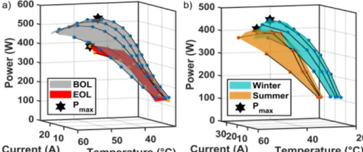
Performance of a FC system is influenced by several factors, such as ambient operating conditions, stack temperature, operating current, degradation phenomenon, and so forth. The variation of these factors can lead to the change of PEMFC stack power delivery capability which is very important in the design of an EMS. For instance, Fig. 1 indicates the output power of a 500-W PEMFC with respect to its operating current and stack temperature in two different conditions. The data have been obtained from experimental tests in Hydrogen Research Institute of University of Quebec in Trois-Rivières. Fig. 1a presents the characteristics of a new PEMFC stack, which is in its beginning of life (BOL) and an old stack which is in its end of life (EOL) after reaching a 20% decrease in the maximum rated power. Fig. 1b shows the characteristics of a 500-W stack in two different seasons with different ambient temperatures (27℃ in Summer and 20℃ in Winter). The stars show the location of maximum power (MP) which changes in each case. Therefore, the online updating of the map seems to be necessary to embrace these impacts on the operation of the stack and provide the requested power from the FCS by the best possible combination of current and temperature. Some considerable efforts have been made to prevent the EMS malfunction owing to these performance drifts by adding a degradation model to the system. In [10], FC degradation is quantified by a simplified electrochemical model and integrated into the cost function of an optimal control-based EMS for a hybrid FC bus to extend the PEMFC lifetime. In [11], an online adaptive ECMS is proposed for a FC-battery-SC powertrain, where the degradation of the PEMFC is considered by the variation of resistance and maximum current density using a first-order polynomial function. The authors show that the battery charge sustenance constraint cannot be satisfied as the PEMFC and battery degrade. In [12], a model predictive control framework is proposed for a FCHEV. The PEMFC degradation is also taken into account using some experimental degradation rates for high, low, and transitional loads. However, degradation and ageing mechanisms are very complex to be modeled. Moreover, the operating conditions which are not included in the PEMFC model, such as humidity and ambient temperature, can also change the maximum efficiency (ME) and MP ranges of the stack that are normally among the utilized constraints while designing an EMS.
Fig. 1. The variation of characteristics in a PEMFC stack, a) lifetime variation, b) seasonal variation.
To evade the mentioned issues about PEMFC modeling, two approaches of extremum seeking and online identification of PEMFC model parameters have come under attention. The former is based on seeking an optimal operating point by means of a periodic perturbation signal in real-time [13, 14]. Such strategies are of interest mostly due to their straightforward implementation. When concurrent identification of several operating points is required in online applications, the optimization function is changed, and an optimization algorithm is used to search for MP and ME points. Regarding online identification, recursive filters are used for tuning the PEMFC parameters through time. The necessary characteristics are then extracted from the updated model. In [15], the authors employ RLS for updating a single-input PEMF model while designing an EMS for a FCHEV. They indicate that the classical strategies are not very efficient when there are performance drifts in the FC system.
C. Contributions
One important aspect that has escaped the attention of many researchers in the domain of EMS for FCHEVs is adopting a systemic approach towards the management of the PEMFC stack while developing a strategy. In the literature, current and temperature are typically regarded as independent control variables. Nonetheless, PEMFC is a multi-physical system with strong dynamic interactions between current and temperature. Regarding the PEMFC as a system provides several degrees of freedom in terms of power supply [16]. A specific requested power from the PEMFC can be supplied by different combinations of current and temperature to improve the efficiency [17]. Several methods have been proposed concerning the thermal/current management of a PEMFC stack. For instance, in [18], a ten-percent power increase is achieved by controlling the PEMFC stack temperature and input hydrogen humidity level using a FLC and a bubble humidifier respectively. In [19], an approach based on electrochemical impedance spectroscopy is proposed where the current of lowest resistance is used to determine the optimum air flow rate and current density considering the influence of the temperature. In [20], a FLC is suggested to regulate the stack temperature of an open cathode PEMFC by acting on the cooling fan speed. However, to the best of the authors’ knowledge, the integration of a simultaneous current and temperature management into the design of an EMS has not been considered before. In this respect, first, an online systemic management scheme is put forward to guarantee the supply of the requested power from the PEMFC stack with the highest efficiency and embrace the effect of performance drifts in this system. Subsequently, two EMSs, namely QP and BLFS, are developed to distribute the power between sources while respecting the limitations of the system. Finally, the effect of including the proposed PEMFC systemic management in the EMSs’ design is scrutinized by performing experimental validations in a hardware-in-the-loop (HIL) set-up. As mentioned earlier, the main contribution of this work lies in the efficiency upgrade of the two mentioned EMSs by utilizing the put forward concurrent current and temperature
systemic management scheme.
D. Paper organization
Section II describes the utilized vehicle characteristics along with the designed HIL platform. The development of the proposed online current and temperature management as well as the EMS is discussed in Section III. Section IV presents the obtained results from the considered scenarios, and the conclusion along with some remarks is given in section V.
II. FUEL CELL HYBRID ELECTRIC VEHICLE SYSTEM
The system utilized in this manuscript is based on a low-speed FCHEV, called Nemo. The powertrain of this vehicle is composed of a 3-phase induction machine, a PEMFC stack, and a battery pack. The power sources are connected in series and the PEMFC acts as a range extender [21]. More details about the specifications of this vehicle are available in [22]. For the purpose of this work, a HIL platform is developed to assess the performance of the EMS. As shown in Fig. 2, a Horizon H-500 PEMFC is used as the real component of this platform and the rest are mathematical models. The specifications of this PEMFC are presented in Table 1. This open-cathode PEMFC system is self-humidified and air-cooled. It includes two fans attached to the FC stack housing to supply the cooling and process air. The hydrogen supply subsystem consists of a hydrogen tank, a manual forward pressure regulator, a hydrogen supply valve, a hydrogen purging valve, and a mass flowmeter. The pressure regulator keeps the pressure of hydrogen between 0.5 and 0.6 Bar. In the anode side, the PEMFC is equipped with 2 valves.
Fig. 2. The developed HIL platform for evaluating an EMS. TABLEI
SPECIFICATIONS OF THE HORIZON H-500FC PEMFC Technical specifications
Number of cells 36
Max Current (shutdown) 42 A Hydrogen pressure 0.5-0.6 Bar Cathode pressure 1 Bar Ambient temperature 5 to 30 °C Max stack temperature 65 °C Hydrogen purity 99.999% dry H2
Size 130 × 220 × 122 mm
The hydrogen inlet valve allows feeding the PEMFC with dry hydrogen. The hydrogen flow rate changes from 0 to 7 𝑙 𝑚𝑖𝑛⁄ with respect to the drawn power from the stack. Hydrogen flow is measured by an OMEGA flowmeter (FMA-A2309) calibrated for hydrogen gas. It utilizes a capillary type thermal technology to directly measure mass flow and does not require any temperature, pressure, or square root corrections. The purge valve acts as the anode outlet and dispels the excess water and hydrogen from the PEMFC flow channels. In this work, cycling purging is performed to recurrently remove accumulated water, hydrogen and nitrogen. As advised by the manufacturer, the PEMFC is purged every 10 s for a duration of 100 ms in order to refill the anode volume with fresh hydrogen. The hydrogen exhaust flow during the purge depends on the pressure difference between the environment and the anode side. After each purge, if the performance is increased around 10%, the pressure of hydrogen is increased a little bit as it is an indication of flooding (as suggested by the manufacturer). This pressure increase helps pushing the extra water out. In addition, the pressure difference between the anode and the cathode must not exceed 0.5 bar to avoid membrane damages. The PEMFC is linked to a National Instrument CompactRIO (NI cRIO-9022) via its controller which regulates the axial fan as well as the input/output valves. This embedded real-time controller has been combined with a compatible CompactRIO Chassis to include integrated C series I/O module slots. The communication between CompactRIO and the PC, where the LabVIEW software is available, is done by an Ethernet connection. The data between the CompactRIO and the PC are transferred every 100 ms. Current, temperature, and voltage of the PEMFC stack are recorded for updating the model. An 8514 BK Precision DC Electronic Load demands a load profile, imposed by the DC-DC converter, from the PEMFC stack. Since Nemo vehicle has a 4-kW PEMFC stack, the output voltage of the 500-W PEMFC is scaled up after the converter in the HIL platform. The performed tests in this work have been conducted in the ambient temperature and humidity levels of 20 ℃and 60 % respectively.
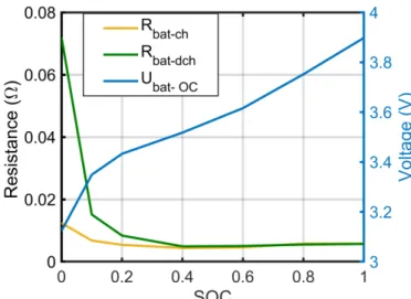
A battery internal resistance model is employed to imitate the behavior of a 6 Ah lithium-ion battery module from Saft Company [23], available in the database of ADVISOR software. In this work, the battery pack is only composed of 20 cells in series. Fig. 3 shows the relationship of battery cell SOC with each of open circuit voltage (𝑈𝑏𝑎𝑡−𝑂𝐶), internal resistance during charging (𝑅𝑏𝑎𝑡−𝑐ℎ), and internal resistance during discharging (𝑅𝑏𝑎𝑡−𝑑𝑐ℎ).
The battery current (𝐼𝑏𝑎𝑡), bus voltage (𝑈𝑏𝑢𝑠), and SOC are calculated by: If 𝑃𝑏𝑎𝑡 > 0 (discharge): { 𝐼𝑏𝑎𝑡= (𝑈𝑏𝑎𝑡−𝑂𝐶(𝑆𝑂𝐶) − √𝑈𝑏𝑎𝑡−𝑂𝐶(𝑆𝑂𝐶)2−4×𝑅 𝑏𝑎𝑡−𝑑𝑐ℎ(𝑆𝑂𝐶)×𝑃𝑏𝑎𝑡 2×𝑅𝑏𝑎𝑡−𝑑𝑐ℎ(𝑆𝑂𝐶) 𝑈𝑏𝑢𝑠= 𝑈𝑏𝑎𝑡−𝑂𝐶(𝑆𝑂𝐶) − 𝐼𝑏𝑎𝑡× 𝑅𝑏𝑎𝑡−𝑑𝑐ℎ(𝑆𝑂𝐶) 𝑆𝑂𝐶(𝑡𝑓) = 𝑆𝑂𝐶(𝑡0) − ∫𝑡0𝑡𝑓𝐼𝑏𝑎𝑡𝑑𝑡 𝐶𝑏𝑎𝑡 (1)
Fig. 3. SOC relationship with open circuit voltage and internal resistance per cell. If 𝑃𝑏𝑎𝑡 < 0 (charge): { 𝐼𝑏𝑎𝑡 = (𝑈𝑏𝑎𝑡−𝑂𝐶(𝑆𝑂𝐶) − √𝑈𝑏𝑎𝑡−𝑂𝐶(𝑆𝑂𝐶)2−4×𝑅𝑏𝑎𝑡−𝑐ℎ(𝑆𝑂𝐶)×𝑃𝑏𝑎𝑡 2×𝑅𝑏𝑎𝑡−𝑐ℎ(𝑆𝑂𝐶) 𝑈𝑏𝑢𝑠= 𝑈𝑏𝑎𝑡−𝑂𝐶(𝑆𝑂𝐶) − 𝐼𝑏𝑎𝑡× 𝑅𝑏𝑎𝑡−𝑐ℎ(𝑆𝑂𝐶) 𝑆𝑂𝐶(𝑡𝑓) = 𝑆𝑂𝐶(𝑡0) − 𝜂𝐶 ∫𝑡𝑓𝐼𝑏𝑎𝑡𝑑𝑡 𝑡0 𝐶𝑏𝑎𝑡 (2)
where 𝑃𝑏𝑎𝑡 is the battery pack power, 𝐶𝑏𝑎𝑡 is the capacity, and 𝜂𝐶 is the coulombic efficiency only during charge (0.98) [24]. The PEMFC stack is linked to the DC bus through a DC-DC converter. This converter is modeled by using a smoothing inductor and a boost chopper as explained in [25].
III. ONLINE SYSTEMIC MANAGEMENT STRATEGY Temperature of a PEMFC stack has an impact on the electrochemical, thermodynamics, electro-kinetics, transport, and water distribution processes, which jointly dictate system efficiency and long-term durability [26]. It is favorable to sustain control over the stack temperature to reach homogeneous distribution. Hence, temperature and indeed its spatial variation should be considered alongside the commonly considered operating conditions, such as current and voltage, while characterizing the PEMFC stack performance and searching for optimum operating points. This is significant in all the PEMFCs and operating modes but is chiefly relevant to the air-cooled PEMFCs in which the input air is responsible for both of reaction and cooling the system [27].
In an open cathode PEMFC, the airflow related to the minimum cooling fan duty cycle can ensure a high oxygen stoichiometry ratio at the rated power of the PEMFC stack [19, 28]. Therefore, the principal impact on the performance is made by the changes in the stack temperature rather than the oxygen supply. Regarding the utilized open cathode PEMFC in this manuscript, the cathode stoichiometry is calculated by [28]:
𝑆𝑂2 = 𝑛̇𝑖𝑛𝑂2 𝑛̇𝑐𝑜𝑛𝑠𝑂2 ⁄ =0.21( 𝜌𝑎𝑖𝑟𝑄𝑎𝑖𝑟 𝑀𝑎𝑖𝑟 ⁄ ) 𝑁𝑐𝑒𝑙𝑙 𝐼 4𝐹 ⁄ (3)
where 𝑆𝑂2 is the oxygen stoichiometry, 𝑛̇𝑖𝑛 𝑂2
is the amount of oxygen supplied to the PEMFC, 𝑛̇𝑐𝑜𝑛𝑠
𝑂2
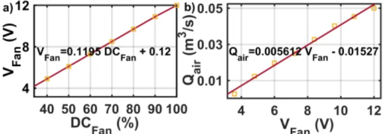
is the consumed oxygen in the electrochemical reaction, 𝜌𝑎𝑖𝑟 is the air density, 𝑄𝑎𝑖𝑟 is the air flow, 𝑀𝑎𝑖𝑟 is the air molar mass, 𝑁𝑐𝑒𝑙𝑙 is the number of cells, and 𝐹 is the Faraday constant. In (3), the only unknown parameter is the airflow (𝑄𝑎𝑖𝑟), which is calculated according to the presented experimental measurements in Fig. 4.
Fig. 4. Cooling fan characteristics, a) fan voltage with respect to duty cycle, and b) air flow with respect to fan voltage.
According to (3) and Fig. 4, even at the minimum duty cycle of the fan (34%), a stoichiometry of around 29 is obtained at the rated power of the PEMFC (448W @ 27A). Such a high oxygen stoichiometry is not unusual for air-cooled open-cathode systems according to the literature [19, 28]. General configuration of the proposed online systemic strategy is shown in Fig. 5. This strategy is based on the proposed work in [16] and has two operating levels of management and control. The management level is responsible for dictating the reference signals to the controllers, and the control level deals with reaching them. In [16], the management level comprised a static 3D power map generated by experimental data. It would determine the reference signal of the temperature controller (FLC) while the reference power of the power controller was assumed to be known. However, such a map is efficient only in a limited operating range as the PEMFC characteristics change through time.
In this work, an online PEMFC model is employed to update the key characteristics of the stack, such as power and
Fig. 5. The systemic current and temperature management and control structure.
efficiency curves, from time to time. The extracted characteristics have two vital roles in this strategy. First, determining a dependable reference signal for the temperature controller through an optimal temperature-versus-power path. Second, providing the EMS with the updated ME and MP points which are utilized to ascertain the requested power from the PEMFC stack. The requested power from the PEMFC stack is indeed the reference signal of the power controller shown in Fig. 5. The two appointed reference signals are then sent to the controllers to be reached. The details about the design and performance of the control level are available in [16]. This work mainly focuses on the online updating of the map and its integration into an EMS.
A. Online mapping
1) Process explanation:
The general process of online mapping in this study is shown in Fig. 6. The core of this process is a semi-empirical PEMFC voltage model which takes the current (𝐼𝐹𝐶), hydrogen partial pressure (𝑃𝐻2), and stack temperature (𝑇𝐹𝐶) as the inputs and estimates the stack voltage (𝑉𝐹𝐶). The hydrogen partial pressure is assumed constant in this work. As discussed in [16], stack temperature mainly depends on the current and cooling fan duty cycle, and it can be represented by a smooth surface. In this respect, a polynomial function is used to create a relationship between the inputs, which are operating current and fan duty cycle, and the output, which is the stack temperature. Indeed, this function provides the stable temperature for each current level with respect to the utilized fan duty cycle. The operating current and its corresponding stable temperature are then used as the inputs of the semi-empirical voltage model, and as a result, the voltage and power curves of the PEMFC are obtained. This map is static and will be used by the EMS for updating the set ME and MP points. The parameters of the voltage model are updated by Kalman filter (KF) using the measured signals from the real PEMFC. As opposed to the semi-empirical model, the polynomial function is updated online by a batch of stable temperature points using a typical least squares method [29]. It should be noted that in the beginning of the process, first, the parameters of the voltage model are updated as it can be done very fast by using the measured data from the real PEMFC. Subsequently, the thermal model is updated when enough measured stable temperature points are captured. Afterwards, the models are updated from time to time.
2) Voltage model:
The utilized semi-empirical model estimates the stack voltage for a number of cells connected in series.
𝑉𝐹𝐶= 𝑁𝑐𝑒𝑙𝑙(𝐸𝑁𝑒𝑟𝑛𝑠𝑡+ 𝑉𝑎𝑐𝑡+ 𝑉𝑜ℎ𝑚𝑖𝑐+ 𝑉𝑐𝑜𝑛) (4) 𝐸𝑁𝑒𝑟𝑛𝑠𝑡= 1.229 − 0.85 × 10⁻³(𝑇𝐹𝐶− 298.15) + 4.3085 × 10⁻⁵𝑇 𝐹𝐶[ln(𝑃𝐻2) + 0.5ln (𝑃𝑂2)] (5) {𝑉𝑎𝑐𝑡= 𝜉1+ 𝜉2𝑇𝐹𝐶+ 𝜉3𝑇𝐹𝐶𝑙𝑛(𝐶𝑂2) + 𝜉4𝑇𝐹𝐶𝑙𝑛(𝐼𝐹𝐶) 𝐶𝑂2= 𝑃𝑂2 5.08×10⁻⁶exp(−498 𝑇⁄ 𝐹𝐶) (6) 𝑉𝑜ℎ𝑚𝑖𝑐= −𝐼𝐹𝐶 𝑅𝑖𝑛𝑡𝑒𝑟𝑛𝑎𝑙 = −𝐼𝐹𝐶(𝜁1+ 𝜁2𝑇𝐹𝐶+ 𝜁3𝐼𝐹𝐶) (7) 𝑉𝑐𝑜𝑛= 𝐵𝑙𝑛(1 − 𝐼𝐹𝐶 𝐼𝑚𝑎𝑥) (8)
Where 𝑉𝐹𝐶 is the stack output voltage (V), 𝑁𝑐𝑒𝑙𝑙 is the number of cells, 𝐸𝑁𝑒𝑟𝑛𝑠𝑡 is the reversible cell potential (V), 𝑉𝑎𝑐𝑡 is the activation loss (V), 𝑉𝑜ℎ𝑚𝑖𝑐 is the ohmic loss (V), 𝑉𝑐𝑜𝑛 is the concentration loss (V), 𝑇𝐹𝐶 is the stack temperature (K), 𝑃𝐻2 is the hydrogen partial pressure in anode side (N m−2), 𝑃 𝑂2 is the oxygen partial pressure in cathode side (N m−2), 𝜉 𝑛(𝑛 = 1 … 4) are the semi-empirical coefficients based on fluid mechanics, thermodynamics, and electrochemistry, 𝐶𝑂2 is the oxygen concentration (mol cm−3), 𝐼 𝐹𝐶 is the PEMFC operating current (A), 𝑅𝑖𝑛𝑡𝑒𝑟𝑛𝑎𝑙 is the internal resistor (Ω), 𝜁𝑛(𝑛 = 1 … 3) are the parametric coefficients, 𝐵 is a parametric coefficient (V), and 𝐼𝑚𝑎𝑥 is the maximum current (A). The explanation of KF integration into this semi-empirical model for parameters estimation is considered redundant in this work as it has been already discussed in [22]. The targeted parameters for estimation in the voltage model vary through time. However, their initial values before the online estimation by KF are: 𝜉1=-0.995, 𝜉2=2.1228×10⁻³, 𝜉3=2.1264×10⁻⁵, 𝜉4=-1.1337×10 -4, 𝜁 1=-0.024, 𝜁2=7.60×10⁻⁵, 𝜁3=-1.06×10⁻³, 𝐵=0.4970. The power of the PEMFC system (𝑃𝐹𝐶−𝑆𝑦𝑠) is obtained by subtracting the power of the PEMFC stack (𝑃𝐹𝐶) from the consumed power by the cooling fan (𝑃𝐹𝑎𝑛) and hydrogen valve (𝑃𝑉𝑎𝑙𝑣𝑒). Fig. 7 shows the consumed power by the cooling fan at each duty cycle obtained by measuring the voltage and current of the fan in different duty cycles (34% to 100%). The power consumed by the purge valve is not noticeable as it has a fixed cyclic purging (every 10 s for duration of 100 ms) and has not been considered in this work. 𝑃𝐹𝐶−𝑆𝑦𝑠= 𝑃𝐹𝐶− 𝑃𝐹𝑎𝑛− 𝑃𝑉𝑎𝑙𝑣𝑒 (9)
𝑃𝐹𝐶= 𝑉𝐹𝐶× 𝐼𝐹𝐶 (10)
𝑃𝐹𝑎𝑛= 𝑐1 𝐷𝐶𝐹𝑎𝑛2+ 𝑐2 𝐷𝐶𝐹𝑎𝑛+ 𝑐3 (11)
𝑃𝑉𝑎𝑙𝑣𝑒= 𝑉𝑉𝑎𝑙𝑣𝑒× 𝐼𝑉𝑎𝑙𝑣𝑒 (12)
Where 𝑐1, 𝑐2, and 𝑐3 are empirical coefficients obtained by fitting a single-variable quadratic polynomial function to the measured data shown in Fig. 7 (𝑐1= 0.001365, 𝑐2= 0.1139, and 𝑐3= -0.9946), 𝑉𝑉𝑎𝑙𝑣𝑒 is the voltage of the Hydrogen valve (12 V), and 𝐼𝑉𝑎𝑙𝑣𝑒 is the current of the Hydrogen valve (0.72 A). The power consumption of the hydrogen valve is constant since it is normally open when the PEMFC starts operating. Hydrogen flow is a function of current and duty cycle and is Fig. 7. The500-W Horizon PEMFC Cooling fan power consumption respecting the duty cycle. estimated by an empirical equation proposed in [16]. 𝑓𝐻2= 𝑎1 𝐼𝐹𝐶+ 𝑎2 𝐷𝐶𝐹𝑎𝑛 100 + 𝑎3 (13)
Where 𝑓𝐻2 is the hydrogen flow (SLPM), and 𝑎𝑛 (𝑛 = 1,2,3) are the fitting parameters obtained by the experimental data (𝑎1= 0.1539, 𝑎2= -0.05308, 𝑎3= 1.657). Finally, the efficiency of the PEMFC system is calculated by: 𝜂𝐹𝐶−𝑆𝑦𝑠= 𝑃𝐹𝐶−𝑆𝑦𝑠 𝑓𝐻2 22.4×60×𝐿𝐻𝑉 (14) where 𝐿𝐻𝑉 is the low heating value of hydrogen (241800 𝐽 𝑚𝑜𝑙⁄ ), and 1/22.4 × 60 is the conversion factor from SLPM to 𝑚𝑜𝑙 𝑠⁄ .
3) Thermal model:
As mentioned earlier, the temperature behavior with respect to current and fan duty cycle can be modeled by a polynomial function. Fig. 8 shows the influence of cooling fan and operating current over the stack temperature of the PEMFC.
Fig. 8. Influence of operating current and fan duty factor over the stack temperature.
This figure has been generated by applying a ramp-up current profile to the PEMFC system in five different fan duty factors, namely 0.25, 0.34, 0.5, 0.7, and 1. At each duty factor, the test is continued until the maximum power of the PEMFC
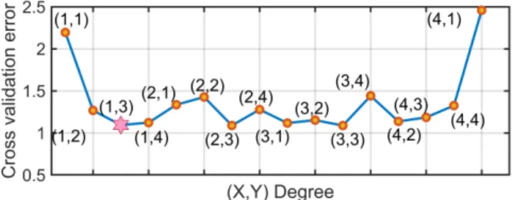
is achieved, and the voltage drop due to the concentration loss is observed. It should be noted that while testing the EMS, the minimum fan duty cycle is set to 34% (not 25%) as it is the minimum level defined by the manufacturer to have a good chemical reaction in all the power ranges. To select a suitable degree for the polynomial-based temperature model, K-fold cross validation is used [30]. Fig. 9 shows the cross-validation error (CVE) for the five-fold data set of this manuscript based on which a proper function should be selected for estimating the stable temperature. The CVE is calculated by:
𝐶𝑉𝐸 = 1 𝑚∑ 𝑅𝑀𝑆𝐸𝑇𝐹𝐶𝑖 𝑚 𝑖=1 (15) 𝑅𝑀𝑆𝐸𝑇𝐹𝐶= √ ∑ (𝑇𝑁1 𝐹𝐶−𝑇̂𝐹𝐶)2 𝑁 (16) where 𝑚 is the number of subsets, which is 5 herein, 𝑅𝑀𝑆𝐸𝑇𝐹𝐶 is the stack temperature root-mean-square error of
each subset, 𝑁 is the number of data points inside each subset, 𝑇𝐹𝐶 is the measured stable temperature, and 𝑇̂𝐹𝐶 is the estimated stable temperature by the polynomial function. The 𝐶𝑉𝐸 has been calculated for several polynomial degrees, as shown in Fig. 9. Apart from overfitting and underfitting problems, it is also significant to avoid increasing the number of parameters since this function will be updated online by least squares method. From Fig. 9, it seems that a third-degree function with respect to the operating current has an acceptable performance as it has achieved a low 𝐶𝑉𝐸. According to Fig. 9, the temperature model is given by: 𝑇𝐹𝐶(𝐷𝐶𝐹𝑎𝑛, 𝐼𝐹𝐶) = 𝑇𝑎𝑚𝑏+ 𝑝1 𝐷𝐶𝐹𝑎𝑛+ 𝑝2 𝐼𝐹𝐶+
𝑝3 𝐷𝐶𝐹𝑎𝑛 𝐼𝐹𝐶+ 𝑝4 𝐼𝐹𝐶2+ 𝑝5 𝐷𝐶𝐹𝑎𝑛 𝐼𝐹𝐶2+ 𝑝6 𝐼𝐹𝐶3 (17) where 𝑇𝐹𝐶 is the stack temperature, 𝑇𝑎𝑚𝑏 is the ambient temperature (20 ℃), 𝐷𝐶𝐹𝑎𝑛 is the duty cycle of the fan, 𝐼𝐹𝐶 is the operating current of the PEMFC stack, and 𝑝𝑛(𝑛 = 1 … 6) are the unknown parameters estimated by least squares method when enough measured data are obtained. The values of these empirical parameters after the first estimation are: 𝑝1=0.0322, 𝑝2=1.7112, 𝑝3=-0.0259, 𝑝4=0.0117, 𝑝5=0.0006, and 𝑝6=-0.001. Fig. 10 indicates the investigation for finding the minimum required time to get stable points for updating the parameters of the temperature model (Fig. 10a) and the number of points needed to do the first estimation (Fig. 10b). Since the final objective of the PEMFC model is to extract the power map, the utilized error in Fig. 10 is the mean absolute percentage error of the estimated PEMFC power (𝑀𝐴𝑃𝐸𝑃𝐹𝐶),
Fig. 9. Evaluation of different polynomial degrees based on 𝐶𝑉𝐸.
Fig. 10. The required time (a) and data points (b) for updating the parameters of the temperature model.
calculated by (18). That means, first, the stable temperature is estimated by the polynomial function, and after that it is sent to the voltage model to predict the output power of the stack. 𝑀𝐴𝑃𝐸𝑃𝐹𝐶 = 100% 𝑁 ∑ | 𝑃𝐹𝐶−𝑃̂𝐹𝐶 𝑃𝐹𝐶 | 𝑁 1 (18) Where 𝑃𝐹𝐶 is the estimated power by using the measured temperature, and 𝑃̂𝐹𝐶 is the estimated power by using the estimated temperature. From Fig. 10a, it can be stated that the extracted parameters at 2 minutes have an acceptable precision (𝑀𝐴𝑃𝐸𝑃𝐹𝐶= 3.77%) as the decline trend of the error becomes
less than 1% after this step. In other words, the error does not decrease considerably after 2 minutes. Moreover, Fig. 10b shows that by having nine measurements, an acceptable estimation can be conducted. As the application of this work will be in FCHEVs which have an energy storage system, it is possible to reach the stable temperature points from PEMFC. Moreover, the primary estimations can be done by recording points in even less than one minute and then the accuracy can be increased by getting more stable points through time. 4) Validation phase:
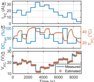
An experimental test has been conducted to evaluate the extraction quality of the power map and other characteristics by using the above-discussed online modeling approach. Fig. 11a presents the applied current profile to the PEMFC stack and Fig. 11b shows the utilized cooling fan duty cycle profile as well as the corresponding stack temperature. The current profile and the measured temperature are sent to the electrochemical model, and the estimated voltage by the PEMFC model is then presented in Fig. 11c. According to this figure, the voltage estimation by the model has a satisfactory quality. It should be noted that the parameters of the semi-empirical model are tuned by KF. The measured stable temperature data as a result of applying the current and the cooling fan duty cycle profiles, shown in Fig. 11, are employed to extract the optimal power line of the stack with respect to current and temperature.
Fig. 12 represents the estimated and measured power line of the utilized PEMFC stack. As is seen in this figure, several combinations of current and temperature can lead to the same power level. In each power line, the intersection of minimum
Fig. 11. Current profile (a), cooling fan duty cycle profile and its corresponding stack temperature (b), and the voltage estimation (c). current and its corresponding temperature is shown with a circle where connecting all the circles leads to an optimal power line. The reference power line has been obtained by conducting several tests since it needs a wide range of data. However, the estimated power line has been attained by the model using the minimum time and data points, as discussed earlier. Fig. 13 shows the corresponding hydrogen consumption of each power line. From this figure, it is seen
Fig. 12. Optimal power line with respect to current and temperature.
Fig. 13. Optimal power line with respect to current and H2 flow.
that each circled optimal point in the estimated power line is equivalent to the minimum hydrogen consumption, implying that the lower the current, the lower the hydrogen flow. Moreover, the interpolated lines in each power level can be mathematically considered as a convex problem which has only one minimum.
B. Energy management strategies
The provided basis in this work regarding online systemic management can be conveniently integrated into most of the existing EMSs in the literature. An EMS or power split strategy, regardless of its type, is expected to determine the reference power from the PEMFC stack. Then, the proposed systemic management is mainly responsible for supplying this reference power by selecting the best combination of PEMFC current and temperature. As the selection of current and temperature comes from an updated experimental map, the supply of the PEMFC reference power, determined by the EMS, is guaranteed with the highest efficiency level. In this section, two EMSs will be discussed to be upgraded by the proposed online systemic management.
1) Quadratic programming-based strategy:
The requested power (𝑃𝑟𝑒𝑞) from the electric motor side is supplied by both of PEMFC system and battery pack. Therefore, the fuel economy of an FCHEV relies on how the requested power is distributed between these two sources. Herein, the objective of the EMS is to find an online optimal power split trajectory which maximizes PEMFC efficiency while respecting the constraints of the system.
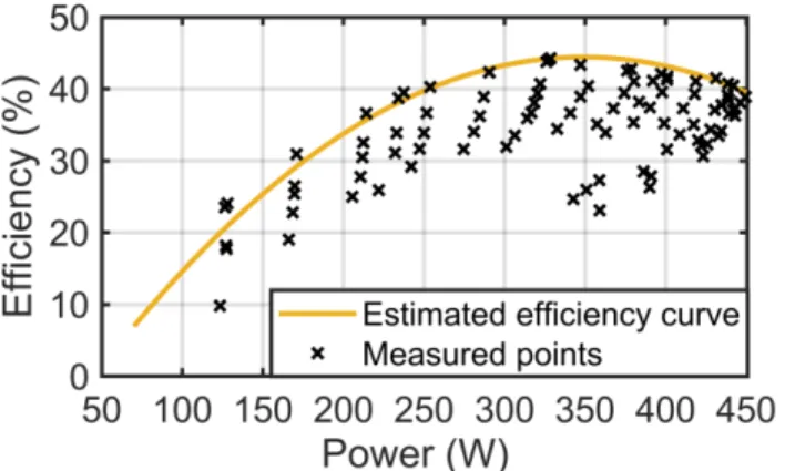
𝑃𝑟𝑒𝑞 = 𝜂𝐷𝐶−𝐷𝐶𝑃𝐹𝐶−𝑆𝑦𝑠+ 𝑃𝐵𝑎𝑡 (19) Where 𝑃𝐵𝑎𝑡 is the battery power and 𝜂𝐷𝐶−𝐷𝐶 is the DC-DC converter efficiency (90%). According to Fig. 14, which has been extracted from the explained online mapping section, the process of maximizing the PEMFC system efficiency can be formulated by a quadratic function as:
max (∑𝑛𝑘=1𝛼2(𝑘)𝑃𝐹𝐶−𝑆𝑦𝑠2+ 𝛼1(𝑘)𝑃𝐹𝐶−𝑆𝑦𝑠(𝑘) + 𝛼0(𝑘)) (20) 𝑛 = 𝑡
Δ𝑡, 𝑛𝜖ℕ (21) where the total time of driving cycle (𝑡) is discretized to 𝑛 time points with respect to the time interval (Δ𝑡). The defined cost function in (20) can be solved by the classical QP method as it is convex in the bounded power ranges shown in Fig. 14. Each cross marker in Fig. 14 represents the location of one measured point in terms of power and efficiency. Each measured point has also a specific current and duty cycle. The estimated curve shows that the highest level for the efficiency curve has been selected.
However, to keep the power sources operation within an admissible range, the following constraints are considered: 𝑆𝑂𝐶𝑚𝑖𝑛≤ 𝑆𝑂𝐶𝑘≤ 𝑆𝑂𝐶𝑚𝑎𝑥 (22) 𝑃𝐹𝐶,𝑚𝑖𝑛 ≤ 𝑃𝐹𝐶,𝑘 ≤ 𝑃𝐹𝐶,𝑚𝑎𝑥 (23) ∆𝑃𝑅𝑖𝑠𝑒,𝑘− 𝑆𝑙𝑒𝑤𝑟𝑎𝑡𝑒,𝑟𝑖𝑠𝑒≤ 0 (24)
Fig. 14. Relationship between PEMFC system efficiency and power. ∆𝑃𝐹𝑎𝑙𝑙,𝑘− 𝑆𝑙𝑒𝑤𝑟𝑎𝑡𝑒,𝑓𝑎𝑙𝑙≤ 0 (25) where the battery SOC should be kept between 50% (𝑆𝑂𝐶𝑚𝑖𝑛) and 90% (𝑆𝑂𝐶𝑚𝑎𝑥), 𝑃𝐹𝐶,𝑚𝑖𝑛 is zero, 𝑃𝐹𝐶,𝑚𝑎𝑥 is determined by the online model, ∆𝑃𝑅𝑖𝑠𝑒,𝑘 is the positive PEMFC power change, 𝑆𝑙𝑒𝑤𝑟𝑎𝑡𝑒,𝑟𝑖𝑠𝑒 is the rising dynamic limitation, ∆𝑃𝐹𝑎𝑙𝑙,𝑘 is the negative PEMFC power change, and 𝑆𝑙𝑒𝑤𝑟𝑎𝑡𝑒,𝑓𝑎𝑙𝑙 is the falling dynamic limitation. According to [15], a dynamic limitation of 50 Ws−1, which means a maximum of 10% of the maximum power per second for rising, and also 30% of the maximum power per second for falling, as suggested in [7], have been considered for the operation of the PEMFC stack. The proposed strategy avoids operation in the open-circuit voltage (OCV) of the PEMFC. When the requested power from the PEMFC decreases to zero, the PEMFC is switched off and it does not operate in OCV. Moreover, to avoid unnecessary on/off cycles in the PEMFC system, the cost function of the QP has been defined based on maximizing the efficiency. PEMFC system efficiency is zero when the current/power of the PEMFC is zero. Therefore, QP avoids using PEMFC in low efficiency region as its objective is to maximize it. QP only decides to turn off the PEMFC to avoid over charging when the battery SOC approaches its upper limit.
The only point that should be reminded here is that since the optimization variable in (20) is 𝑃𝐹𝐶−𝑆𝑦𝑠, the battery SOC calculation should be related to this optimization variable so that the defined constraint in (22) can be explained. The presented SOC calculation in (1) and (2) can be presented as: 𝑆𝑂𝐶̇ (𝑘) = 𝑓(𝑆𝑂𝐶(𝑘), 𝑃𝑏𝑎𝑡(𝑘)) (26)
Here, the battery power can be substituted by the difference between requested power and the PEMFC system power as: 𝑆𝑂𝐶̇ (𝑘) = 𝑓(𝑆𝑂𝐶(𝑘), 𝑃𝑟𝑒𝑞(𝑘) − 𝜂𝐷𝐶−𝐷𝐶𝑃𝐹𝐶−𝑆𝑦𝑠(𝑘)) (27)
Since 𝑃𝑟𝑒𝑞(𝑘) is obtained by imposing acceleration to the system, (27) can be rewritten in terms of the optimization variable (𝑃𝐹𝐶−𝑆𝑦𝑠), by using a new function (𝐹).
𝑆𝑂𝐶̇ (𝑘) = 𝐹(𝑆𝑂𝐶(𝑘), 𝑃𝐹𝐶−𝑆𝑦𝑠(𝑘)) (28)
2) Bounded load following strategy (BLFS):
The second EMS of this study is a commonly used rule-based real-time approach in the literature [7, 31]. BLFS is a hysteresis-based EMS to distribute the power between the sources of a FCHEV. It normally limits the operation of the PEMFC stack within ME and MP points and mostly provides three modes of operation including ON/OFF, 𝑃𝐹𝐶,𝑚𝑖𝑛, and 𝑃𝐹𝐶,𝑚𝑎𝑥 with respect to the battery SOC level and requested power. To ensure a low hydrogen consumption, the PEMFC ME point is used as the 𝑃𝐹𝐶_𝑚𝑖𝑛 mode. In fact, the hydrogen consumption and the degradation of the stack are higher between the open circuit voltage and the best efficiency point region of the PEMFC. Therefore, when the PEMFC is turned on, the ME mode is activated. 𝑃𝐹𝐶_𝑚𝑎𝑥 mode, which sets the stack on its MP, is triggered when the battery SOC reaches the minimum SOC level. The only time that PEMFC works between OFF and 𝑃𝐹𝐶,𝑚𝑖𝑛 is the transitions from OFF to 𝑃𝐹𝐶,𝑚𝑖𝑛 due to the slew rate limitations. The details of BLFS are available in [7]. The constraints regarding the battery SOC and PEMFC slew rates are the same as QP strategy in the previous section.
IV. EXPERIMENT AND RESULTS ANALYSIS
To show the effect of online systemic management incorporation into the EMS design, five scenarios, namely the proposed EMSs based on systemic management and the updated map (QPSys−Up and BLFSSys−Up), the proposed EMSs using commercial controller and the updated map (QPCom−Up and BLFSCom−Up), and QP using commercial controller and an outdated map (QPCom−Out) are taken into consideration under two driving cycles, worldwide harmonized light-duty vehicles test cycles (WLTC_class 3) and West Virginia Interstate Driving Schedule (CYC_WVUINTER).
In QPSys−Up and BLFSSys−Up case studies, the proposed systemic management uses the estimated PEMFC characteristics shown in Figs. 12 and 13 to determine the right current and temperature combinations for supplying the reference power imposed by the EMS to the PEMFC system. In fact, the reference temperature is determined by the optimal power-versus-temperature line and after that FLC controls the cooling fan to reach the reference temperature. In QPCom−Up and BLFSCom−Up case studies, the imposed power by the EMS is supplied by the PEMFC using the commercial fan controller of the PEMFC stack and the updated characteristics. The comparison of QPSys−Up and BLFSSys−Up with QPCom−Up and BLFSCom−Up case studies illustrates the effect of including systemic management in the EMS design which is one of the main objectives of this manuscript. QPCom_Out case study supplies the power by using the commercial fan controller and outdated characteristics of the PEMFC stack. The outdated map belongs to the presented PEMFC in its BOL in Fig. 1a. By using this map, the EMS is fed by false inputs because the characteristics map is different with the utilized PEMFC on the HIL set-up. The comparison of QPCom−Up and QPCom−Out
illuminates the importance of online updating in the performance of the vehicle.
Fig. 15 and Fig. 16 compare the performance of the five above-discussed scenarios for WLTC_class 3 and CYC_WVUINTER driving cycles, respectively. As is seen in Figs. 16a and 16a, WLTC_class 3 contains low-, medium-, and high-speed regimes while CYC_WVUINTER solely includes high-speed condition. Figs. 15b and 16b present the supplied power by the PEMFC stack for the five cases. According to these figures, the reference power imposed to PEMFC stack by the EMS is the same in QPSys−Up and QPCom−Up and also in BLFSSys−Up and BLFSCom−Up for both driving cycles. However, the reference power of QPCom−Out is different as QP receives data from an outdated map in this case study. Figs. 15c and 16c show the temperature evolution which are different in each case due to the cooling fan operation. Figs. 15d and 16d represent the battery SOC variation at each considered case. As is seen, the battery SOC variation in both QPSys−Up and QPCom−Up is similar, as opposed to QPCom−Out case. SOC evolution is also the same in the BLFS strategies. The designed EMSs try to meet the requested power from the system by respecting the defined limits for battery SOC and PEMFC stack. Moreover, they tend to keep a high level of battery SOC while the vehicle is under operation. The analyses carried out in Fig. 15 and Fig. 16 show the general performance of the developed EMSs in the discussed driving conditions and scenarios. However, the influence of PEMFC systemic management integration over the performance of the utilized QP and BLFS EMSs should be
Fig. 15. The EMS performance under WLTC_class 3, a) driving speed and the corresponding traction power, b) power split by different strategies, c) PEMFC temperature evolution, and d) battery SOC variation.
Fig. 16. The EMS performance under CYC_WVUINTER driving cycle, a) driving speed and the corresponding traction power, b) power split by different strategies, c) PEMFC temperature evolution, and d) battery SOC variation.
further considered. In this regard, the distribution of the drawn current from the PEMFC stack to meet the requested power in each of the considered driving scenarios is illustrated in Fig. 17. Form this figure, it is seen that the drawn current from the PEMFC stack by the proposed systemic EMSs (QPSys−Up and BLFSSys−Up) is clearly lower than the commercial controller case studies (QPCom−Up and BLFSCom−Up) under the two considered driving cycles. Fig. 17a and Fig. 17b compare the performance of the QP based EMS with and without systemic management along with the outdated map case study. Fig. 17a shows that the PEMFC stack has worked in almost all the operating current range since the driving cycle contains a lot of changes. However, the QPSys−Up has managed to supply the power with lower current levels which are in the efficient operation zone of the stack. From Fig. 17b, it is seen that the PEMFC stack has worked mostly in the efficient zone while the QPCom−Up has used higher current levels to fulfil the expectations. QPCom_Out has a very different current distribution compared to other cases as its set signals are based on the outdated characteristics. It goes to very high current region according to Fig. 17b to be able to supply the requested power. According to Fig. 17c and Fig.17d, the systemic BLFS (BLFSSys−Up) uses lower current levels in the efficient zone compared to the commercial controller (BLFSCom−Up). Moreover, in Fig. 17c, PEMFC has some transitions between off and almost 18 A owing to the changes in the WLTC_class 3 driving cycle while in Fig. 17d, it mostly operates within ME and MP points.
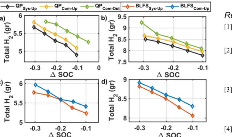
stack as well as the influence of initial and final battery SOC over the performance of the studied cases. In this regard, each test is repeated five times starting with different initial SOCs (60%, 65%, 70%, 75%, and 80%). Subsequently, the difference between initial and final SOC (∆SOC) versus the hydrogen consumption is plotted. Form this figure, it is clear that under both driving cycles, regardless of the initial and final battery SOC, the QPSys−Up achievs the lowest and the QPCom_Out reaches the highest hydrogen consumption. Comparing QPSys−Up and QPCom−Up shows that hydrogen consumption has decreased up to 3.7% and 2.6% in Fig. 18a and Fig. 18b respectively due to the integration of the proposed systemic management. Moreover, comparison of QPCom−Up and QPCom_Out shows that ignorance of adaptation to the PEMFC health state has increased hydrogen consumption up to 3.2% and 6.6% in Fig. 18a and Fig. 18b respectively. Regarding the BLFS, inclusion of the systemic management has declined the hydrogen consumption up to 3.4% in Fig. 18c and 3% in Fig. 18d.
Fig. 17. The distribution of the drawn current from the PEMFC stack, a) and c) WLTC_class 3, b) and d) CYC_WVUINTER.
Fig. 18. Hydrogen consumption for various initial Battery SOCs, a) and c) WLTC_class 3, b) and d) CYC_WVUINTER.
V. CONCLUSION
This paper proposes a new methodology to increase the efficiency of an EMS in a low-speed FCHEV. The EMS works based on an online systemic current and temperature
management of the PEMFC stack and determines the reference requested power as well as the reference temperature to efficiently distribute the power between the sources. Since the constraints of the EMS are updated by an online model of the PEMFC, the variation of operating conditions and degradation cannot cause mismanagement in the operation of the vehicle. Two EMSs, namely QP and BFLS, have been developed to verify the effect of the proposed systemic management on the hydrogen consumption. The two strategies, which are premised on the online systemic management (QPSys−Up and BLFSSys−Up), are tested under two driving cycles (WLTC_class 3 and CYC_WVUINTER) and compared with three other case studies: QP and BFLS using an updated map (QPCom−Up and BLFSCom−Up), and QP using an outdated map (QPCom_Out), where the reference temperature to reach the assigned power by the EMSs is determined by the fan commercial controller in all the three cases. The comparative study illustrates that having an outdated PEMFC map can deteriorate the fuel economy of the studied vehicle up to 6.6% (comparison of QPCom−Up and QPCom_Out strategies). Moreover, incorporating the systemic management into the EMSs can enhance the hydrogen economy up to 3.7% in QP and 3.4% in BFLS.
Looking forward, some prospects for extending the scope of this paper remain as follows:
• Testing the effect of the proposed systemic management in this study on the performance of other common EMSs in this domain.
• Extending the idea of systemic management to water management of the PEMFC stack to devise an adaptive purging procedure for vehicular applications. It will create a link between the EMS policy and the purging cycle for a better water distribution.
• Developing an online adaptation scheme and systemic management for the battery pack as the second power source of a FCHEV.
References
[1] Z. Li, A. Khajepour, and J. Song, "A comprehensive review of the key technologies for pure electric vehicles," Energy, vol. 182, pp. 824-839, 2019/09/01/ 2019.
[2] N. Sulaiman, M. A. Hannan, A. Mohamed, P. J. Ker, E. H. Majlan, and W. R. Wan Daud, "Optimization of energy management system for fuel-cell hybrid electric vehicles: Issues and recommendations," Applied Energy, vol. 228, pp. 2061-2079, 2018/10/15/ 2018.
[3] C. M. Martinez, X. Hu, D. Cao, E. Velenis, B. Gao, and M. Wellers, "Energy Management in Plug-in Hybrid Electric Vehicles: Recent Progress and a Connected Vehicles Perspective,"
IEEE Transactions on Vehicular Technology, vol. 66, no. 6, pp.
4534-4549, 2017.
[4] R. Zhang, J. Tao, and H. Zhou, "Fuzzy Optimal Energy Management for Fuel Cell and Supercapacitor Systems Using Neural Network Based Driving Pattern Recognition," IEEE
Transactions on Fuzzy Systems, vol. 27, no. 1, pp. 45-57, 2019.
[5] Y. Yan, Q. Li, W. Chen, B. Su, J. Liu, and L. Ma, "Optimal Energy Management and Control in Multimode Equivalent Energy Consumption of Fuel Cell/Supercapacitor of Hybrid Electric Tram," IEEE Transactions on Industrial Electronics, vol. 66, no. 8, pp. 6065-6076, 2019.
[6] X. Wu, X. Hu, X. Yin, L. Li, Z. Zeng, and V. Pickert, "Convex programming energy management and components sizing of a
plug-in fuel cell urban logistics vehicle," Journal of Power
Sources, vol. 423, pp. 358-366, 2019/05/31/ 2019.
[7] M. Carignano, V. Roda, R. Costa-Castelló, L. Valiño, A. Lozano, and F. Barreras, "Assessment of Energy Management in a Fuel Cell/Battery Hybrid Vehicle," IEEE Access, vol. 7, pp. 16110-16122, 2019.
[8] H. Lim and W. Su, "Hierarchical Energy Management for Power-Split Plug-In HEVs Using Distance-Based Optimized Speed and SOC Profiles," IEEE Transactions on Vehicular Technology, vol. 67, no. 10, pp. 9312-9323, 2018.
[9] J. Chen, C. Xu, C. Wu, and W. Xu, "Adaptive Fuzzy Logic Control of Fuel-Cell-Battery Hybrid Systems for Electric Vehicles," IEEE Transactions on Industrial Informatics, vol. 14, no. 1, pp. 292-300, 2018.
[10] Y. Wang, S. J. Moura, S. G. Advani, and A. K. Prasad, "Power management system for a fuel cell/battery hybrid vehicle incorporating fuel cell and battery degradation," International
Journal of Hydrogen Energy, vol. 44, no. 16, pp. 8479-8492,
2019/03/29/ 2019.
[11] H. Li, A. Ravey, A. N’Diaye, and A. Djerdir, "Online adaptive equivalent consumption minimization strategy for fuel cell hybrid electric vehicle considering power sources degradation," Energy
Conversion and Management, vol. 192, pp. 133-149, 2019/07/15/
2019.
[12] X. Hu, C. Zou, X. Tang, T. Liu, and L. Hu, "Cost-optimal energy management of hybrid electric vehicles using fuel cell/battery health-aware predictive control," IEEE Transactions on Power
Electronics, pp. 1-1, 2019.
[13] N. Bizon and P. Thounthong, "Real-time strategies to optimize the fueling of the fuel cell hybrid power source: A review of issues, challenges and a new approach," Renewable and Sustainable
Energy Reviews, vol. 91, pp. 1089-1102, 2018/08/01/ 2018.
[14] D. Zhou, A. Al-Durra, I. Matraji, A. Ravey, and F. Gao, "Online Energy Management Strategy of Fuel Cell Hybrid Electric Vehicles: A Fractional-Order Extremum Seeking Method," IEEE
Transactions on Industrial Electronics, vol. 65, no. 8, pp.
6787-6799, 2018.
[15] K. Ettihir, L. Boulon, and K. Agbossou, "Optimization-based energy management strategy for a fuel cell/battery hybrid power system," Applied Energy, vol. 163, pp. 142-153, 2016/02/01/ 2016. [16] M. Kandidayeni, A. Macias, L. Boulon, and S. Kelouwani, "Efficiency Enhancement of an Open Cathode Fuel Cell through a Systemic Management," IEEE Transactions on Vehicular
Technology, pp. 1-1, 2019.
[17] L. Yin, Q. Li, T. Wang, L. Liu, and W. Chen, "Real-time thermal Management of Open-Cathode PEMFC system based on maximum efficiency control strategy," Asian Journal of Control, vol. 21, no. 4, pp. 1796-1810, 2019.
[18] K. Ou, W.-W. Yuan, M. Choi, S. Yang, and Y.-B. Kim, "Performance increase for an open-cathode PEM fuel cell with humidity and temperature control," International Journal of
Hydrogen Energy, vol. 42, no. 50, pp. 29852-29862, 2017/12/14/
2017.
[19] Q. Meyer et al., "Optimisation of air cooled, open-cathode fuel cells: Current of lowest resistance and electro-thermal performance mapping," Journal of Power Sources, vol. 291, pp. 261-269, 2015/09/30/ 2015.
[20] Y. Wang, F. Qin, K. Ou, and Y. Kim, "Temperature Control for a Polymer Electrolyte Membrane Fuel Cell by Using Fuzzy Rule,"
IEEE Transactions on Energy Conversion, vol. 31, no. 2, pp.
667-675, 2016.
[21] J. Höflinger, P. Hofmann, and B. Geringer, "Experimental PEM-Fuel Cell Range Extender System Operation and Parameter Influence Analysis," 2019. Available:
https://doi.org/10.4271/2019-01-0378
[22] M. Kandidayeni, A. O. M. Fernandez, A. Khalatbarisoltani, L. Boulon, S. Kelouwani, and H. Chaoui, "An Online Energy Management Strategy for a Fuel Cell/Battery Vehicle Considering the Driving Pattern and Performance Drift Impacts," IEEE
Transactions on Vehicular Technology, pp. 1-1, 2019.
[23] V. H. Johnson, "Battery performance models in ADVISOR,"
Journal of Power Sources, vol. 110, no. 2, pp. 321-329,
2002/08/22/ 2002.
[24] Y. Zhou, A. Ravey, and M.-C. Péra, "Multi-mode predictive energy management for fuel cell hybrid electric vehicles using Markov driving pattern recognizer," Applied Energy, vol. 258, p. 114057, 2020/01/15/ 2020.
[25] J. P. F. Trovão, M. Roux, M. É, and M. R. Dubois, "Energy- and Power-Split Management of Dual Energy Storage System for a Three-Wheel Electric Vehicle," IEEE Transactions on Vehicular
Technology, vol. 66, no. 7, pp. 5540-5550, 2017.
[26] S. Strahl, A. Husar, and M. Serra, "Development and experimental validation of a dynamic thermal and water distribution model of an open cathode proton exchange membrane fuel cell," Journal of
Power Sources, vol. 196, no. 9, pp. 4251-4263, 2011/05/01/ 2011.
[27] P. W. Majsztrik, M. B. Satterfield, A. B. Bocarsly, and J. B. Benziger, "Water sorption, desorption and transport in Nafion membranes," Journal of Membrane Science, vol. 301, no. 1, pp. 93-106, 2007/09/01/ 2007.
[28] S. Strahl, A. Husar, P. Puleston, and J. Riera, "Performance Improvement by Temperature Control of an Open-Cathode PEM Fuel Cell System," Fuel Cells, vol. 14, no. 3, pp. 466-478, 2014. [29] S. Kelouwani, K. Adegnon, K. Agbossou, and Y. Dube, "Online
System Identification and Adaptive Control for PEM Fuel Cell Maximum Efficiency Tracking," IEEE Transactions on Energy
Conversion, vol. 27, no. 3, pp. 580-592, 2012.
[30] J. Lever, M. Krzywinski, and N. Altman, "Model selection and overfitting," Nature Methods, vol. 13, p. 703, 08/30/online 2016. [31] K. Ettihir, L. Boulon, and K. Agbossou, "Energy management
strategy for a fuel cell hybrid vehicle based on maximum efficiency and maximum power identification," IET Electrical
Systems in Transportation, vol. 6, no. 4, pp. 261-268, 2016.
Mohsen Kandidayeni (S’18) was born in Tehran
(Iran) in 1989. His educational journey has spanned through different paths. He received the B.S. degree in Mechanical Engineering in 2011, and then did a master’s degree in Mechatronics at Arak University (Iran) in 2014. He joined the Hydrogen Research Institute of University of Quebec, Trois-Rivières, QC, Canada, in 2016 and received the Ph.D. degree in Electrical Engineering from this university in 2020. He was a straight-A student during his Master and Ph.D. programs and the recipient of a doctoral scholarship from the Fonds de recherche du Québec–Nature et technologies (FRQNT). His research interests include energy-related topics such as hybrid electric vehicles, fuel cell systems, energy management, Multiphysics systems, modeling and control.
Alvaro Macias F. (M’17) was born in Mexico City,
in 1992. He received the B.S. degree in Mechatronics engineering from Tec de Monterrey, Guadalajara, Mexico, in 2015 and the M.S. degree in electrical engineering from Université du Québec à Trois-Rivières, Canada, in 2018. He is currently pursuing the Ph.D. degree in electrical engineering at Université du Québec à Trois-Rivières, Canada. From 2015 to 2016, he worked as Research and Development in the Centro de Investigación y de Estudios Avanzados del Instituto Politécnico Nacional, Mexico. His current research interest includes the development of energy management strategies for fuel cell systems, passive and active system configuration, and fuel cell modeling.
Loïc Boulon (M'10,SM'15) received the master
degree in electrical and automatic control engineering from the University of Lille (France), in 2006. Then, he obtained a PhD in electrical engineering from University of Franche-Comté (France). Since 2010, he is a professor at UQTR and he works into the Hydrogen Research Institute (Full Professor since 2016).
His work deals with modeling, control and energy management of multiphysics systems. His research interests include hybrid electric vehicles, energy and power sources (fuel cell systems, batteries and ultracapacitors). He has published more than 120 scientific papers in peer-reviewed international journals and international conferences and given over 35 invited conferences
all over the word. Since 2019, he is the world most cited authors of the topic "Proton exchange membrane fuel cells (PEMFC); Fuel cells; Cell stack" in Elsevier SciVal. In 2015, Loïc Boulon was general chair of the IEEE-Vehicular Power and Propulsion Conference in Montréal (QC, Canada). Prof. Loïc Boulon is now VP-Motor Vehicles of the IEEE Vehicular Technology Society and he found the "International Summer School on Energetic Efficiency of Connected Vehicles" and the "IEEE VTS Motor Vehicle Challenge". He is the holder of the Canada Research Chair in Energy Sources for the Vehicles of the future.
Sousso Kelouwani (M’00–SM’17) received the
B.S. and the M.Sc.A. degrees from Université du Québec à Trois-Rivières, Trois-Rivières, QC, Canada, in 2000 and 2002, respectively, and the Ph.D. degree (automation and systems) from École Polytechnique de Montréal, Montréal, QC, Canada, in 2010, all in electrical engineering. Holder of the Canada Research Chair in Energy Optimization of intelligent transportation systems, Sousso Kelouwani is also the holder of the Industrial Research Chair DIVEL in Intelligent Navigation of Autonomous Industrial Vehicles. Full professor of Mechatronics at the Department of Mechanical Engineering at UQTR, he holds four patents in the United States, his research interest focuses on the optimization of energy systems for vehicular applications, advanced driving assistance techniques, eco-energy navigation of autonomous vehicles, hybridization of energy sources for vehicles (batteries, fuel cells, hydrogen generators, etc.) in harsh weather conditions. In 2017, he received the Environment Award of the Grand Prix for Excellence in Transport from the Quebec Transportation Association (AQTr) for the development of a hydrogen range extender based on a hydrogen generator for electric vehicles. He was also a recipient of the Canada Governor General's Gold Medal in 2000. Moreover, he has worked with several Canadian transportation companies to develop intelligent, energy-efficient and driverless vehicles.