THÈSE PRÉSENTÉE À
L'UNIVERSITÉ DU QUÉBEC À TROIS-RIVIÈRES
COMME EXIGENCE PARTIELLE DU DOCTORAT EN GÉNIE ÉLECTRIQUE
PAR
SHERIF MOUSSA
NOUVEAUX TRANSMETTEURS/RÉCEPTEURS POUR LES SYSTÈMES SANS FIL MIMO-OFDM : DE L'IDÉE À LA MISE EN OEUVRE
Université du Québec à Trois-Rivières
Service de la bibliothèque
Avertissement
L’auteur de ce mémoire ou de cette thèse a autorisé l’Université du Québec
à Trois-Rivières à diffuser, à des fins non lucratives, une copie de son
mémoire ou de sa thèse.
Cette diffusion n’entraîne pas une renonciation de la part de l’auteur à ses
droits de propriété intellectuelle, incluant le droit d’auteur, sur ce mémoire
ou cette thèse. Notamment, la reproduction ou la publication de la totalité
ou d’une partie importante de ce mémoire ou de cette thèse requiert son
autorisation.
DOCTORAT EN GÉNIE ÉLECTRIQUE (PH.D.)
Programme offert par l'Université du Québec à Trois-Rivières
NOUVEAUX TRANSMETTEURSIRÉCEPTEURS POUR LES SYSTÈMES SANS FIL MIMO-OFDM : DE L'IDÉE À LA MISE EN OEUVRE
PAR
SHERIF MOUSSA
Adel O. Dahmane, directeur de recherche Université.du Québec à Trois-Rivières
Frédéric Domingue, président du jury Université du Québec à Trois-Rivières
Habib Hamam, codirecteur de recherche Université de Moncton
Jean-Yves Chouinard, évaluateur externe Université Laval
Rachid Beguenane, évaluateur externe Collège militaire royal du Canada
Multiple Input Multiple Output (MIMO) and Orthogonal Frequency Division Multiplexing (OFDM) are two major techniques that have recently been combined and proposed for 4G wireless communication systems. Coding schemes such as Space Time Block Code (STBC) and Space Frequency Block Code (SFBC) are used with MIMO-OFDM to provide higher system throughput and better diversity gains. While STBC is simple to implement, it does not scale weIl for any arbitrary number of antennas. In addition to that, it is not designed for frequency selective fading channels. On the other hand, SFBC achieves full diversity in frequency selective multipath channels. However, it has fairly complex implementation, and share with the first scheme the fact that both do not support multi-user access. In this thesis, a novel transmission scheme is developed to effectively enable multiple access by joint code design across multiple antennas, subcarriers, OFDM frames, and users. Such system will benefit from the combined space, frequency, time as weIl as multi-user diversity. Hence, better spectrum efficiency is achieved while improving bit error rate performance with respect to signal-to-interference ratio. The proposed scheme uses either parity bit selected or permutation techniques to choose the spreading code at the transmitter side. As a result, the detection at the receiver is greatly reduced due to the fact that identifying the spreading code directly yields the transmitted data symbols. Additionally, this thesis also investigates the hardware implementation challenges of the proposed algorithms. The s.econd contribution of this
thesis is the introduction of a systematic design methodology and real-time prototyping platform. It allows converting the proposed algorithms from Matlab onto the target FPGA prototyping platform in a systematic way. The third contribution of the thesis is the introduction of hardware architectural optirnization techniques in order to reduce area, power and time. Among those optimization methods that are proposed, a pipelined architecture in which only one IFFT/FFT block is shared among aIl transmittinglreceiving antennas, an efficient 10w complexity algorithm for despreading based on counters and comparators, and an optimized architecture for complex matrix inversion using Gauss-Jordan elimination (GJ-elimination). FinaIly, the Fixed-Point optirnized FPGA architecture for MIMO-OFDM Transceiver is developed, where the maximum aIlowed performance 10ss due to quantization is defined, the tradeoffs between BER performance and area reduction are investigated.
1 would like to express my deepest gratitude to my advisor Dr. Ade1 Dahmane for the tremendous support during my Ph.D study, for his patience, motivation, enthusiasm, and immense knowledge. His guidance he1ped me to define the scope of my research and to be able to complete the work of this thesis. 1 simply could not wish for a better or friendlier supervisor.
1 wou Id like also to thank my wife, Imane Djaaboub. She was always there cheering me up and stood by me through the good and bad times. Her support, encouragement, and persistent motivational attitude were vital for me to finish my Ph.D degree.
Table of contents
Abstract ...... iii
Acknowledgement .... v
Table of contents ...... vi
List of tables ... xi
List of figures .......... ...... xiii
List of acronytTIS ...... xvi
Chapitre 1 -Introduction ... 1
1.1 Wireless system development .... 2
1.2 Background and Motivation ... 5
1.3 Thesis Objectives and Scope ..... 8
1.4 Publications ..... 9 1.4.1 Published ... 9 1.4.2 Submitted ... 10 1.5 Thesis Organization ... 10 Chapitre 2 - MIMO-OFDM .......... 12 2.1 Introduction ....... 12
2.2 Conventional MIMO-OFDM system ........ 14
2.2.2 OF DM Mathematical model ... ~ ... 18
2.2.3 OFDMA ... 19
2.2.4 MIMO-OFDM Mathematical model ... 20
2.2.5 MIMO Detection techniques ... 23
2.3 MIMO-OFDM coding techniques ... .32
2.3.1 Space-Time coded MIMO-OFDM .. ~ ... .34
2.3.2 Space Division Multiplexing (SDM) ... ..40
2.3.3 Space-Frequency Block Coding MIMO-OFDM ... ..42
2.4 Conclusion ... 45
Chapitre 3 - MIMO-OFDM with parity bit selected and permutation spreading ... ..47
3.1 MIMO-OFDM with parity bit selected and permutation spreading ... ..48
3.2 Simulation set-up ... 56
3.2.1 Power requirements ... 56
3.2.2 Channel conditions ... 56
3.2.3 Parameters for simulations ... 57
3.3 Numerical simulation results ... · ... 58
3.4 Conclusion ... 65
Chapitre 4 - Design & Implementation ofMIMO-OFDM system ... 67
4.1 Implementation platform ... 68
4.1.1 UART algorithm ... 71
4.1.2 UART Implementation results ... 77 4.1.3 Matlab interface ... 78
4.2 Design & Implementation ofMIMO-OFDM system ... 79
4.2.1 Spreading code selection: ...... 81
4.2.1· Modulation and data spreading ... 82 4.2.2 SeriaI to ParaUel circuit: .... 83
4.2.3 IFFT block ...... 86
4.2.4 Cyclic Prefix insertion .... 86
4.2.5 Cyclic Prefix removal: ..... 87
4.2.6 Channel effect removal: .... 88
4.2.7 Code Despreading: ..... 95
4.2.8 Maximum Likelihood Detection: ... 99
4.1 Function validation ... 1 02 4.2 Synthesis results ... 104
4.3 Conclusion ... 108
Chapitre 5 - Design optimization ............................................. 109
5.2 Pipelined Architecture ... 11 0
5.2.1 IFFT with pipelined architecture: ... .110
5.2.2 FFT with pipelined architecture: ... 114
5.2.3 Implementation results for pipelined architecture: ... 115
5.3 Despreading optimization: ... 116
5 4 M . atnx mverSIOn optImlzatIOn. . . . . . : ... 1 20 5.4.1 GAUSS-JORDAN algorithm ... 121
5.5 Fixed point architecture: ... 130
5.6 Conclusion ... 136
Chapitre 6 - Summary and future work ... .l37 6.1 Summary ... 137
6.2 Future work ... 140
6.2.1 Adaptive coding ... 140
6.2.2 Adaptive modulation ... 140
6.2.3 Integration'with channel estimation ... 141
References ... : ... 142
Appendix A - Functional Simulation ... 150
Transrnitter function simulation: ... 150
Annexe B - Résumé de la thèse en français ...... .. 157
B.2 Introduction ..... , ... 158
8.2.1 Problématique ... 158
8.2.2 Objectifs de la thèse .......................... . 161
8.2.3 Organisation de la thèse ....................................... 162
8.3 MIMO-OFDM avec étalement à bit de parité sélectionné et à permutation ................................. ........ 164
B.3.2 Résultats de simulation numérique ... .... 166
BA Conception et hnplémentation FPGA du système MIMO-OFDM proposé ......................................................... 167
B.4.2 Résultats d'implémentation ... 168
Table 3-1 Spreading permutations for MIMO-OFDM with 4 antennas ... 52
Table 3-2 Simulation parameters ... 58
Table 4-1 Consumed Resourees for UART Module in Virtex 5 FPGA ... 77
Table 4-2 Hardware resourees consumed by Transmitter in XC5VLX50T ... 105
Table 4-3 Timing summary for the Transmitter in XC5VLX50T ... 1 05 Table 4-4 Hardware resourees eonsumed by channel removal in XC5VLX50T ... 105
Table 4-5 Timing summary for the channel removal in XC5VLX50T ... 106
Table 4-6 Hardware resourees eonsumed by despreading module in XC5VLX50T ... 1 06 Table 4-7 Timing summary for the despreading module in XC5VLX50T ... 106
Table 4-8 Hardware resourees eonsumed by Reeeiver module in XC5VLX50T. ... 106
Table 4-9 Timing summary for the Reeeiver module in XC5VLX50T ... 107
Table 4-10 Hardware resourees eonsumed by Transeeiver in XC5VLX50T ... 1 07 Table 4-11 Timing summary for the Transeeiver in XC5VLX50T ... 1 07 Table 4-12 Hardware resourees eonsumed by Transeeiver in XC6VLX195T ... 108
Table 5-1 Hardware resourees eonsumed by pipelined transmitter.. ... 115
Table 5-2 Timing summary for pipelined transmitter.. ... 116
Table 5-3 Consumed resourees for optimized despreading ... 120
Table 5-4 Consumed resourees for Floating-Point non-optimized Vs optimized Transeeiver ... 130
Table 5-5: Timing summary for Floating-Point non-optimized Vs optimized Transeeiver ... 130
Table 5-6: Consumed resources for optimized Transceiver with Floating-Point
Figure 2-1 OFDM Frequency spectrum [33] .... 14
Figure 2-2 Orthogonal overlapping spectral shape for OFDM [34] ...... 15
Figure 2-3 Conventional OFDM System ..... 16
Figure 2-4 OFDM CP insertion ...... 17
Figure 2-5 Multi-user OFDM system [37]. ... .20
Figure 2-6 Simplified block diagram ofMIMO-OFDM system ..... 21
Figure 2-7 SIC architecture model .............. 29
Figure 2-8 Performance' comparison for MIMO detection algorithms (2 Tx, 2Rx and BPSK modulation) ... 32
Figure 2-9 Alamouti STBC 2 Tx and 1 Rx ...... 36
Figure 2-10 Alamouti STBC 2 Tx and 2 Rx ... 37
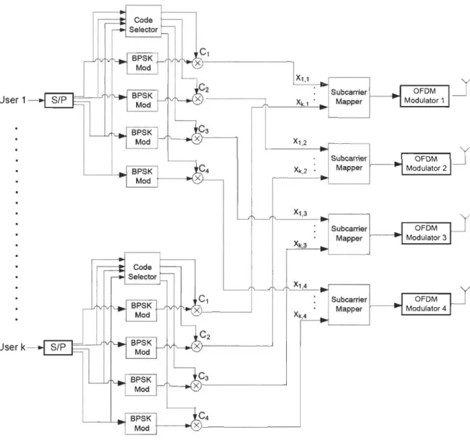
Figure 3-1 4X4 MIMO-OFDM transmitter with Parity Bit Selected Spreading .... ............ ..49
Figure 3-2 Time-Frequency mapping ...... 53
Figure 3-3 MIMO-OFDM receiver for parity bit selected and permutation spreading for Nr = 4 ... 54
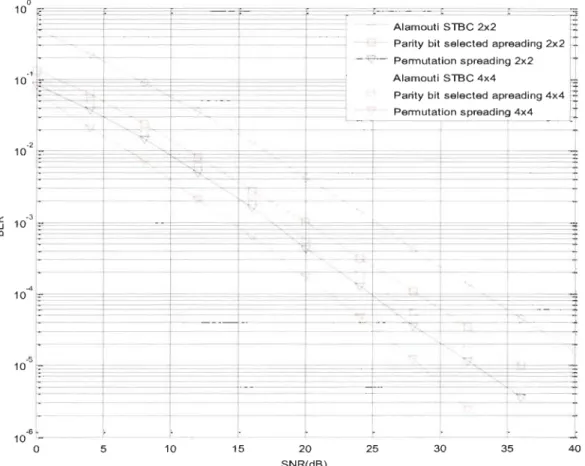
Figure 3-4 BER performance for 2X2 MIMO-OFDM with parity bit selected spreading, permutation spreading, and Almouti STBC ...... 60
Figure 3-5 BER performance for MIMO-OFDM schemes with 2X2 and 4X4 configurations ..... 61
Figure 3-6 BER performance comparison for MIMO-OFDM with permutation spreading, when Nc = 8 and Nc = 16 .... 62
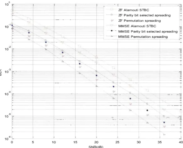
Figure 3-7 BER performance for MIMO-OFDM schemes with MMSE and ZF equalizations ... 64
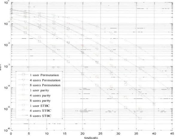
Figure 3-8 BER comparison for multi-user MIMO-OFDM with parity bit selected and permutation spreading Vs MIMO-OFDMA with
STBC ... 65
Figure 4-1 Design methodology flow chart ... 69
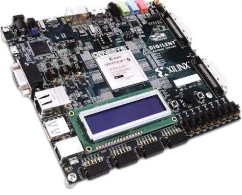
Figure 4-2 Genesys board ... 70
Figure 4-3 UART seriai bit structure ... 71
Figure 4-4 Block diagram ofa UART receiving subsystem ... 72
Figure 4-5 UART receiver FSM ... 74
Figure 4-6 Interface circuit block diagram ... 75
Figure 4-7 Block diagram of a UART transmitter subsystem ... 76
Figure 4-8 UART receiver subsystem simulation results ... ; ... 78
Figure 4-9 UART transmitter subsystem simulation results ... 79
Figure 4-10 MIMO Transceiver block diagram ... 80
Figure 4-11 Parity code selection block ... 82
Figure 4-12 Floaring-Point representation structure ... 82
Figure 4-13 Permutation code selection block ... 83
Figure 4-14 BPSK modulation and spreading for parity scheme ... 84
Figure 4-15 BPSK modulation and spreading for permutation scheme ... 84
Figure 4-16 Seriai to ParaUel block ... 85
Figure 4-17 RAM control unit FSM ... 86
Figure 4-18 Cyclic Prefix insertion block ... 87
Figure 4-19 Cyclic Prefix FSM ... : ... 88
Figure 4-20 Architecture for channel equalization block ... 89
Figure 4-21 Determinant calculation circuit ... 91
Figure 4-22 Matrix Inversion block ... 91
Figure 4-24 Complex matrix multiplication circuit ... 93
Figure 4-25 Channel removal control unit FSM ... 95
Figure 4-26 Code-zero matching tilter ... 96
Figure 4-27 Code-one matching filter ... 97
Figure 4-28 Code-zero absolute power calculation block ... 98
Figure 4-29 Absolute compare ... 98
Figure 4-30 ML circuit for 00 and 01 code set ... 100
Figure 4-31 ML circuit for Il and 10 code set ... l 0 1 Figure 4-32 Despreading control unit FSM ... 1 03 Figure 5-1 Pipelined transmitter for 2X2 MIMO-OFDM ... 111 Figure 5-2 Pipelined IFFT FSM ... 112 Figure 5-3 Output FSM for pipelined IFFT ... 113
Figure 5-4 Output Ram for the pipelined IFFT ... 113
Figure 5-5 Pipelined receiver for 2X2 MIMO-OFDM ... 114
Figure 5-6 Pipelined FFT FSM ... 115
Figure 5-7 Flow chart for the proposed despreading algorithm ... 118
Figure 5-8 Simulation comparison for MF despreading and optimized despreading algorithm ... 119
Figure 5-9 Proposed architecture for optimized GJ-elimination ... 124
Figure 5-10 Complex multiplier architecture ... 125
Figure 5-11 Complex Divider architecture ... 125 Figure 5-12 Word length VS BER performance for MIMO-OFDM quantization ... 131
Figure 5-13 Fixed-Point Design flow for MIMO-OFDM ... 134 Figure 5-14 Matlab simulation for MIMO-OFDM receiver with Fixed-Point
3G-LTE 4G CP CSI D-BLAST DSTBC FFT FPGA IEEE IFFT ISI LDPC LOS
3rd Generation-Long Term Evolution
4th Generation
Cyclic Prefix
Channel State Information
Diagonal - Bell Laboratories Layered Space-Time Architecture
DifferentiaI Space Time Block Coding
Fast Fourier Transform
Field Programmable Gate Array
Institute of Electrical and Electronics Engineers
Inverse Fast Fourier Transform
Inter-Symbollnterference
Low Density Parity Check
MIMO ML MMSE MRC NLOS OFDM PAM PAPR QAM QOSTBC QPSK rms SFBC SISO SNR STBC
Multiple Input Multiple Output
Maximum Likelihood
Minimum Mean Square Error
Maximal Ratio Combining
Non Line of Sight
Orthogonal Frequency Division Multiplexing
Pulse Amplitude Modulation
Peak to Average Power Reduction
Quadrature Amplitude Modulation
Quasi-Orthogonal Space Time Block Codes
Quadrature Phase-Shift Keying
root mean square
Space Frequency Block Coding
Single Input Single Output
Signal to Noise Ratio
STFBC
SUI VBLAST TAST
WLAN
Space-Time-Frequency Block Coding
Stanford University Interim
Vertical-Bell Laboratories Layered Space-Time Threaded Algebraic Space-Time
Over the la st twenty years, wireless communication systems technology has expanded at a fast pace. Data rates and the quality of service (QoS) requirements are constantly reviewed and improved in order to ensure that users get the desired satisfaction of their wireless communication experience. Wireless communication systems and networks will have to become ever more efficient and flexible to be able to compensate for the lirnited availability of radio frequency (RF) spectrum due to various regulations. As such, wireless communication systems have to have the ability to generate a constantly expanding high spectral performance, more extensive data rates, and greater number of users employing the wireless system at the same rime. The efficiency of the spectrum is increased by the utilization of multiple antennas at the transmitter as weIl as the receiver end. This creates what is known as a multiple-input/multiple-output radio channel (MIMO) [1][2], different from the customary single-input/single-output radio channel (SISO). MIMO in combination with- orthogonal frequency-division multiplexing (OFDM) (MIMO-OFDM) have been identified as a promising approach for high spectral efficiency wideband systems. The demand for extensive data rates and high channel capacity requires improved receiver implementations and architectural design. In order to achieve this, a balance between hardware complexity and operational performance must be established.
The purpose of this thesis is threefold: to propose highly efficient algorithms of a reasonable complexity for MIMO-OFDM communication system ; to design a real-tirne Field Programmable Logic Array (FPGA) architectural model for the proposed transmitter and
receiver algorithms; and to put forward efficient design methodology to translate algorithms to FPGA architectural models. This first chapter will mainly be concemed with outlining the motivations behind the improved MIMO-OFDM transmitter-receiver model to support high data rate. In addition, the existing literature on MIMO-OFDM systems will be reviewed and the
challenges of developing algorithms and FPGA architectural models will be identified,
particular stress being put on the necessity of an efficient methodology with regard to the transformation of algorithms to architectural models. AIl these aspects will be drawn together to define the purpose of the study. Furthermore, the organization of the thesis will be presented
with the summary of contributions in design methodology, algorithm optimization, FPGA
architectures and joint optimization of algorithms and architectures.
1.1 Wireless system development
Wireless communication has developed over the past twenty years from being a limited technology used by a handful of specialists to becoming integrated into a wide variety of electronic devices available to the general public. With the advent of data-centric applications such as the Internet, mobile communication, or wireless local area networks (WLANs), in the early nineties, wireless communication started its way into everybody's daily life. New products (e.g., the iPhone or the iPad) and services (e.g., digital-TV or on-demand video strearning) calI for higher throughput and better quality of service which require new concepts and standards for wireless communication. Third Generation (3G) wireless systems were first implemented in
Japan in 2001 to meet the above requirements. The International Telecommunications Union
endorsed the following third generation wireless networks: CDMA2000, wideband CDMA, and
The introduction of 3G wireless networks led ta the development of a wide range of
multimedia applications, including online gaming, Internet browsing, video streaming.
Nevertheless, despite its improved features, 3G has not yet manage to provide solutions for such issues as Multiple Access Interference (MAI) and Inter Symbole Interference (ISI). As a result, Fourth Generation (4G) wireless networks have begun to be developed in arder ta rectify the shortcomings of the previous generations of wireless systems. The main targets of 4G wire1ess systems are bandwidth expansiqn, data rate increase, extended coverage and reduced co st.
The International Mobile Telecommunications Advanced (IMT -Advanced) specifications requirements for 4G standards were published in March 2008 by the communications division of the International Telecommunications Union-Radio (ITU-R). The specifications included a maximum speed of 100 megabits per second in the case of high mobility communication and 1 gigabit per second for low mobility communication [3].
Mobile WiMAX and Long Terrn Evolution LTE systems are frequently classified as 4G by wireless service providers, despite the fact that they do not reach the established peak rate of 1
Gbit/s, and thus not abiding by the specifications of IMT -Advanced. ITU-R made a concession
on 6th December, 2010, namely that the aforementioned systems, and other 3G systems, could
be categorized as 4G, despite not meeting the specifications of IMT -Advanced, if they could be
demonstrated ta be precursors of the versions that abide by the specifications of IMT -Advanced and show "a substantiallevel of improvement in performance and capabilities with respect to the initial third generation systems currently deployed" [4].
Mobile WiMAX Release 2 (also known as Wireless MAN-Advanced or IEEE 802.16m') and LTE Advanced (LTE-A) are IMT-Advanced compliant backwards compatible versions of the
above two systems, standardized during the spring 20 Il, and promising peak bit rates in the order of 1 Gbitls. Services are expected in 2013 [5].
The objectives of 4G wireless networks include increasing the data transmission rate,
reduced latency, and high reliability (reduction of wireless disconnection), by adapting packet-optirnized radio access systems that sus tain bandwidth distribution. Furthermore, 4G systems seek to decrease the price of infrastructure equipment and user terminaIs, as weIl as to use a modulation structure with a higher performance than the CDMA scheme employed by 3G networks, to maximize the use of communication bandwidth. These objectives caU for a complete reorganiz~tion of the physicallayer and the system architectural mode!.
OFDM is the modulation scheme employed by 4G systems to improve spectral efficiency. It is a broadband multi-carrier modulation scheme where the available bandwidth is subdivided into orthogonal narrow-band sub-carriers. OFDM is known since the late 1960's [6], the developments in semièonductor and computer technology have made OFDM a useful and functional scheme, in contrast to earlier days when the hardware technology available in the 1960s was not suitable to the application of the OFDM scheme. Nowadays, however, OFDM has become the preferred option for wireless communication systems due to a number of reasons, including more straightforward channel equalization in contrast to single carrier schemes, stable against frequency selective fading, and high spectral efficiency. Systems that currently employ OFDM are digital audio broadcasting (DAB), digital video broadcasting terrestrial (DVB-T), digital video broadcasting-handheld (DVB-H), WLANs, WiMAX, the majority of the long-term evolution (LTE) 4G systems, as weU as a number of short-range systems with ultra bandwidth (UWB). What is more, OFDM can also be applied to wired
systems, such as data modems for asymmetric digital subscriber line (ADSL) and very high-speed digital subscriber line (VDSL).
1.2 Background and Motivation
In order to increase the data rate and the communication link robustness, 4G systems employs MIMO schemes alongside OFDM. The advantage of MIMO schemes is that they can reach higher throughput than SISO systems at the same bandwidth and transmit power. Wireless MIMO systems send and receive information over two or more antennas often shared among many users in case of multi-user system. The signaIs reflect off of objects in the environment causing multiple paths. In conventional systems, these multi-paths cause interference and fading. However, MIMO systems combine the multiple fading paths and users' signaIs to overcome multi-user interference and fading, and thereby increase data throughput and reduce Bit Error Rate (BER) as compared to SISO systems. On the other hand, MIMO communication is targeted toward wideband systems which suffer from frequency-selective fading, and as a result the ISI will exist in the system. To mitigate this ISI effect and simplify the channel equalization, MIMO is combined with OFDM in order to convert the frequency-selective channel into a set ofparallel frequency-flat fading channels. Transmission using MIMO-OFDM is used to either increase the robustness of the system or the data rate. In a ri chI y scattered environment, transmit diversity play an important role to maintain the robustness of the wireless communication system. Transmission schemes that exploit diversity use spatial dimensions to add more redundancy, thus keep the data rate equivalent to SISO-OFDM system in order to increase the BER performance. Space-Time Coding is the principal of generating redundancy by coding across time and spatial dimensions [7]-[13], Space time Block Coding (STBC) [14] is the most widely used examples that employs STC scheme. On the other hand, Space Division
Multiplexing (SDM) is employed if the algorithm uses different antennas to transmit multiple data symbols over the channel. SDM schemes are used if high data rates are the main objective of the system [15]-[20].
Both STe and SDM coding schemes cannot achieve multipath diversity and were proposed for flat fading channel and not suitable for frequency selective fading channels. These two problems could be solved if more frequency diversity is introduced to the system. MIMO-OFDM provides the opportunity to code the transmitted symbols over different antennas (space) and sub-carriers (frequency), this coding scheme is known as Space-Frequency Block Coding (SFBC) and it can exploit the multipath diversity. Three dimensional coding over space, time and frequency is also known as Space-Time-Frequency Block Coding (STFBC). Both transmission schemes have recently been proposed in the literature [21 ]-[29]. However, the system complexity is a major obstacle and the decoding complexity problem has to be tackled. Additionally, most of the existing ST/SF codes are designed for single user systems only, for multiple access channels (MAC), the single-user ST/SF codes are always applied to each user independently, which results a reduced transmission rate. For example in conventional MIMO-OFDMA, us ers are separated in different frequency bands (sub-channels), and each user is coded separately using STBe or SFBC, leading to data rate reduction for each user when the number of users is increasing. The above reasons calI for a new transmission scheme to enables multiple access by joint code design across multiple antennas, OFDM frames (time), subcarriers, and users.
The significant performance improvements of the MIMO-OFDM systems cornes at the cost of increasing complexity of signal decoding at the receiver end. For example, in spatial multiplexing the linear increase in data rate with the minimum number of antennas at the transmitter and receiver end, is achieved with a more than !inear increase in decoder complexity
irrespective of the nature of the used decoding algorithms. What is more, maximization of the potential benefits of multiple antennas technology necessitates even more complex algorithms, coming close to or surpassing the technological and economicallimits of the integrated circuits technology.
According to Moore's Law, the chip's transistor density doubles every two years, which put a maximum limit on the system performance improvement rate. On the other hand, according to
Shannon's Law, algorithms grow in complexity more rapidly than chips grow in density in
order to reach the maximum channel capacity. This creates a gap between the algorithmic
complexity and the hardware performance, the gap between·the complexity of algorithms and
battery capacity are even more pronounced, which caUs for an efficient design of both more
compact and more power efficient architectures.
The most complex component of a MIMO-OFDM receiver is the detector, whose role is to separate the spatially multiplexed data streams at the receiver end. InitiaUy, only the complexity
order of MIMO-OFDM receiver algorithms has been examined; however, this is appropriate
only in the case of qualitative comparisons between different decoding algorithms, results of
such an analysis are not particularly relevant to system implementation. On the other hand, a more thorough analysis of the level of algorithm complexity was developed for digital signal
processor (DSP) implementation [30]. However, DSP implementations cannot meet the
requirements (in terms of throughput) of currently emerging and future wideband MIMO-OFDM systems. As a result, FPGA architectural models are required for the implementation of
highly complex decoding algorithms. However, to make sure that the only factor that influences
the performance of the system is the wireless channel capacity, and not the receiver technology, additional developments of high-throughput wideband MIMO-OFDM systems are required.
Conventionally, the algorithm researchers and the hardware design teams work separately [31][32], this leads to the fact that many algorithms proposed are not realistic for real-time implementation due to high complexity and numerical stability problems. This thesis proposes a development environment that lets designers model an entire ~ystem accurately, inc1uding the behavior and interaction of hardware and software subsystems that represent the system platform parameters such as input data and wireless channel.
1.3 Thesis Objectives and Scope
The objective of this thesis is to propose high performance algorithms with realistic complexity and real-time optimized FPGA architectures for the MIMO-OFDM Transceiver. First, in order to reduce the detection algorithm complexity at the receiver side, and at the same time improve the MIMO-OFDM performance, a novel transmission scheme for MIMO-OFDM based on the parity bit selected and permutation block spreading methods is proposed. In this scheme, the transmitted data is coded across space, time and frequency domains. The coding is done using a spreading code where the choice of this code is determined by the parity bits of the transmitted message vector across the multiple antennas. The proposed scheme enables multiple access by joint code design across multiple antennas, OFDM frames, subcarriers, and users. It will bene fit from the combined space, time and frequency diversity and allow users to share subcarriers with a manageable level of multi-user interference. Hence, better spectrum efficiency is achieved while improving bit error rate performance with respect to signal-to-interference rate.
The second objective lS to develop platform architecture for real-time prototyping
environment. In the proposed platform, the communication between Matlab and FPGA board is managed directly,through the Universal Asynchronous Receive and Transmit (UART). In this
thesis, UART core functions are implemented using VHDL and integrated into the MIMO-OFDM FPGA chip to achieve compact, stable and reliable data transmission, which effectively represent a complete hardware design platform for MIMO-OFDM system.
The third objective is to develop an end to end Floating-Point FPGA architecture for the proposed MIMO-OFDM Transceiver scheme. The proposed architecture· is divided into sub-modules where suitable optimization techniques are proposed for each sub-module in order to reach the overall optimized architecture.
1.4 Publications
1.4.1 Published
1. S. Moussa, Ahmed M.Abdel Razik' A.O. Dahmane, and H. Hamam "FPGA Implementation of Floating-Point Complex Matrix Inversion Based On Gauss-Jordan Elimination," CCECE 2013, May 5th to 8th, 2013, Regina, Saskatchewan, Canada.
2. S. Moussa, A.O. Dahmane, C. D'Amours and H. Hamam "MIMO-OFDM with Parity Bit Selected Block Spreading," 2nd international conference on consumer electronics,
communications and networks (CECNET 2012), Three Gorges, Hubei, China, April 21st-23rd,2012.
3. S. Moussa, A.O. Dahrnane, C. D'Amours and H. Hamam "MIMO-OFDM with Permutation Block Spreading," 14th International Conference on Advanced Communication Technology, Pyeongchang, Republic of Korea., February 19-22,2012.
4. S. Moussa, A.O. Dahmane, C. D'Amours and H. Hamam "OFDM with Permutation Block Spreading," GCC Conference and Exhibition, 19-22 Feb. 2011, Dubai, UAE.
5. S. Moussa, A.O. Dahmane, C. D'Amours and H. Hamam "OFDM with Parity Bit Selected Block Spreading," 10th IEEE lCT Conference, 14-18 April 2010, Doha, Qatar.
1.4.2 Submitted
1. S. Moussa, Ahmed M.Abdel Razik A.O. Dahmane, C. D'amours and H. Hamam "FPGA Implementation of MIMO-OFDMA based on parity bit selected and permutation spreading", submitted to: IEEE Transactions on Circuits and Systems 1.
1.5 Thesis Organization
Chapter 2 provides an overview of OFDM transmission systems including its mathematical model, and then its advantages and disadvantages are highlighted. Next, the combination of MIMO systems with OFDM is then described and MIMO-OFDM model is introduced, followed by a comprehensive review of the existing MIMO detection techniques and their associated BER performance and complexity analysis. Finally, MIMO-OFDM transmission schemes are categorized into three main categories Spatial Division Multiplexing (SDM), Space Time Coding (STC), and Space Frequency Coding (SFC), where the performance of these schemes are analyzed and compared.
Chapter 3 presents the new MIMO-OFDM scheme based on the parity bit selected and pemmtation block spreading. M athemati cal model of the proposed technique is given and simulations are presented for different number of transmitlreceive antennas, different modulation, different spreading code length, and different equalization techniques.
Chapter 4 presents FPGA design methodology for MIMO-OFDM systems, which allows converting the proposed algorithms onto the target prototyping platform in a systematic way. Additionally, detailed implementations for real-time prototyping environment based on UART
are also presented. Then, the RTL model for the individual blocks in the proposed MIMO-OFDM system is introduced. Detailed implementations and the potential drawbacks in each module are also provided. The synthesis results, which include the hardware resources usage,
latency, and power consumption are presented and analyzed. Finally, functional verification results are introduced for major modules in the system.
Chapter 5 provides the optimization process for the proposed MIMO-OFDM FPGA architecture. Optimized and efficient architectures are proposed and designed for the key functional module of the systems. These efficient designs include pipe1ined architecture for IFFT IFFT modules, low complexity architecture for the despreading module, low complexity architecture for matrix inversion using GJ-elimination, and finally the complete design is converted to Fixed-Point representation, then the tradeoffs between BER performance and area reduction are investigated and the final results are introduced and analyzed.
Chapter 6 gives the thesis conclusion. The main results and conclusions are surnmarized.
2.1 Introduction
The main target of next generation wireless technologies such as 4G is to provide high speed data transmission rate to satisfy the needs of the emerging new applications. The requirements of 4G wireless communication could be summarized as, 100 Mb/sec data rate in outdoor environment and 1 Gb/sec in indoor channels. Henee a significant bandwidth efficiency
improvement is required in order to main tain the frequency spectrum in the order of 100 MHz.
The main challenge of high speed single carriers wireless transmission lies in the frequency selectivity of the channel, which means that the multipath delay spread of the channel is quite large due to the large bandwidth and leads to severe intersymbol interferenee (ISI). In order to overcome the ISI problem, the duration of the transmirted symbol must be much larger than the delay spread of wireless channels. In multi-carrier's transmission system such as OFDM, the entire channel is divided into many narrow-band subchannels, which are transmirted in paraUel to maintain high-data rate transmission and, at the same time, to increase the symbol duration in order to mitigate the ISI effect. In addition to that, many advanced techniques, such as adaptive loading, transmit diversity, and reeeiver diversity, could be used with OFDM to improve transmission efficiency.
Recently MIMO communication which consists of multiple transmit and receive antennas are used extensively to increase the transmission rate, it is considered as the key ·solution for fading channels in rich scartering environment. Compared with SISO, a MIMO system can improve the capacity by a factor of the minimum number of transmit and receive antennas for
flat fading or narrow-band channels. For wideband transmission, it is natural to combine OFDM with MIMO to deal with frequency selectivity of wireless channels and to obtain diversity and/or capacity gains. Therefore, MIMO-OFDM has widely been used in various wireless systems and standards.
The coding structure of the transmitted signal plays a major role on the performance and
capacity of MIMO-OFDM system. Several transmission sc~emes have been proposed for
MIMO system to improve transmission performance and/or increase the throughput. These
schemes of coding can be divided into two broad categories: Space Time Coding (STC) and
Space Division Multiplexing (SDM). The former scheme is mainly used to increase the
robustness of the system, while the later one is used to increases the maximum data rate
attainable by the system.
This chapter begins with an overvIeW of OFDM transmission systems including its
mathematical model, then its advantages and disadvantages are highlighted. Next,
MIMO-OFDM model is introduced, followed by a comprehensive review of the existing MIMO
detection techniques and their associated BER performance and complexity analysis. A few
examples of such algorithms include Maximum-Likelihood (ML) algorithm, the Zero-forcing
(ZF) algorithm, the Minimum Mean Square Error (MMSE) algorithm, and the V-BLAST
algorithm. Finally, MIMO-OFDM transmission schemes are categorized and the pros and cons
of each scheme are described in details, in order to serve as a base for introducing the novel
MIMO-OFDM transmission scheme based on parity bit selected and permutation, which will be
2.2 Conventional MIMO-OFDM system
2.2.1 OFDM system model
OFDM stands for orthogonal frequency division multiplexing. It is a subdivision of frequency division multiplexing in which multiple sub-carriers on adjacent frequencies are utilized in a single channel. In OFDM system, spectral efficiency is maximized by overlapping sub-carriers. Generally these sub-carriers can interfere with one another. But in OFDM, they do not interfere with each other because sub-carriers are orthogonal to each other. Due to this fact OFDM can maximize spectral efficiency without channel interference. The spectrum of OFDM system in frequency domain is represented in Figure 2-1.
Individual Sub-Channels Channel Bandwidth
1 \
(Bw) ! ~ ~i
V
I
\\
FrequencyBandwidth (Bw)
=
1/ Symbol Rate (Rs)Figure 2-1 OFDM Frequency spectmm [33]
Orthogonality of Sub-Channel Carriers
As described above, the sub carriers are orthogonal in OFDM systems, which mean that each carrier spectrum in frequency domain has a null value at the center frequency of each of
the other carriers in the system. This allows these carriers to be as close as possible to each other, hence better spectral efficiency. In another words, orthogonality enables concurrent transmission on almost every sub-carrier in frequency space without interference as shown in Figure 2-2. So at the receiver side distinct sub-carriers can be easily extracted. In conventional FDM system on the other hand, this overlapping of sub-carriers is not possible, as a result a guard band between each carrier is used to avoid inter-carrier interference.
0.9 0.8 0.7 0.6 .... Q) ~ 0.5 0 Cl.. 0.4 0.3 0.2 0.1 0 0 200 400 600 800 1000 1200 Frequency
Figure 2-2 Orthogonal overlapping spectral shape for OFDM [34]
OFDM TransmitterlReceiver architecture:
Classic model of an OFDM transmitter and receiver is shown in Figure 2-3. Figure 2-3(a) shows OFDM transmitter and Figure 2-3(b) shows OFDM receiver. The transmitter converts digital data which is to be transmitted, into a subcarrier mapping of amplitude and phase and then using the Inverse Fast Fourier Transform (IFFT), digital data is converted into time domain signal representation from spectral representation and a cyclic prefIx (CP) is added. Then to transmit the OFDM signal, the time domain signal is mixed with required frequency through
frequeney multiplexing. The reverse operation is performed at the reeeiver end as shown in
Figure 2-3(b). When the modulated OFDM signal arrives at the receiver, the RF signal is mixed with base band for proeessing and the CP is removed. Then, the signal speetrum is eonverted to frequeney domain using Fast Fourier Transform (FFT). Then phase and amplitude of the subearrier is extracted out and demodulated back to digital data. The IFFT and FFT are both the opposite funetions of each other. The suitable term to describe them rests on whether the signal is being generated or received.
BPSK
Modulation---
--.
c 0t:
Data
a..
1- (j) LL ID-..
-
CI)-Generator
(f) LL ca.
a.
BPSK
() Modulation---(a) OFDM Transmitter
BPSK
DeMod ..--1 >-(f) 1 1 01
Data out
I
~
1-
1 1- Ea.
1a..
1 LL ID 1 -1 0:: 1 LL (j) 1~
BPSK
1 DeMod (b) OFDM RecieverCyclic Prefix Insertion:
In wireless transmission system, the radio signal gets reflected back from waIls, buildings,
mountains and aIl other objects in the transmission environment causing multiple signaIs to arrive at the receiver at different time. This phenomenon is known as multipath transmission. At the OFDM receiver side, multipath channel presents time distortion where the duration of each OFDM symbol is increased. As a result the received symbols interfere with each other and produce the intersymbol interference (lSI) which is very popular in OFDM systems. The symbol rate of OFDM signal is much less than a single carrier transmission technique. For example, in a single carrier system with BPSK modulation the bit rate directly determines the symbol transmission rate. But in OFDM, the whole bandwidth is subdivided into Nf subcarriers
which results in Nf -times lower symbol rate than that of single carrier transmission. Thus the effect of intersymbol interference is reduced in multipath transmission through OFDM, making OFDM a natural resistant to ISI. The system can be further improved if we add guard periods,
which is a cyclic copy, this is done by replicating the OFDM symbol end and appending it to the start of the OFDM frame as shown in Figure 2-4. The addition ofthis guard period results in the extension of symbol waveform but it greatly reduce ISI caused by multipath transmission.
Channel
GI Symbol Symbol
•
C: J symbol
J/
symbol symbol symbol
2.2.2 OFDM Mathematical model
In OFDM the infonnation stream is converted into Nf paraUel streams via seriaI to paraUel (SIP) converter as shown in Figure 2-3, where Nfis the number of subcarriers before CP insertion. These paraUel streams are modulated using BPSK. The f(h OFDM symbol is given by [35]:
X (t)
=
"N ~-i S pet _ kT)ej21rftk Ln_o k.n
Where T is the OFDM symbol duration, and
T
Sk = [Sk.O,Sk.1I ".,Sk.Nt-i ]
(2.1)
(2.2)
is the Nf paraUel data streams for one OFDM frame before CP insertion. The subscript T represents the transpose operator and pet) is the pulse shaping for each symbol. Ifwe consider rectangular pulse shaping wavefonn:
{
l,
°
<S, t <S,T
pet) =
0, otherwise
(2.3)
and that each subcarrier and the OFDM symbol are sampled Nf times per frame interval, the modulated wavefonn of(2.1) becomes:
X (mT) = LN
ri
S ej2rrnm/N tk Nt n=O k.n ,m = 0,1, ... ,Nf - l (2.4)
Rence, the inverse fast Fourier transform (IFFT) is used to modulate these substreams to their respective subcarrier frequencies:
(2.5)
The resulted paraUel symbols after OFDM modulation is converted into ci seriai stream and a CP is inserted. CP duration is selected to be larger than the channel delay to avoid ISL At the receiver, the signal is converted from seriaI to paraUel and the CP is removed, then the FFT is used to demodulate and take decision according to the employed modulation. In case of BPSK, the decision function is simply the sign function.
2.2.3 ()j<1)Jk[4
OFDMA stands for Orthogonal Frequency Division Multiple Access and it is the multiple user version of OFDM. As shown in Figure 2-5, in this system a subset members of sub-carriers are assigned to individual user dynamically, through the use of TDMA (based on timeslots) or
FDMA (separate channels), hence the system support simultaneous users transmission.
Although there are many advantages of OFDMA, its flexibility to resource allocation and
robustness to frequency selective fading are considered the main benefit. By using OFDMA, every user has its own unique set of sub-channels as shown in Figure 2-5 and the base station
can allocate the subcarriers to users dynamically [36]. If high quality of service (QoS) has been requested by specifie user, more resources (more power, large number of sub-channels and higher level of modulation) can be applied to this user.
The major advantages of OFDMA could be summarized as follow:
• Deployment flexibility at different frequency bands with little modification needed with the air interface.
Pilot Subcarriers
~
User 1 Data SubcarriersFrequency
Guard Band Guard Band
Figure 2-5 Multi-user OF DM system [37]
• By spreading the carriers all over the used spectrum, frequency diversity could be
introduced to the system.
• Gives excellent coverage by enabling single frequency network coverage.
• By applying different carrier permutation between different users in different cells,
interferences in neighboring cells is averaged.
• Cyclic permutation is used to overcome interference within the cell.
2.2.4 MIMO-OFDM Mathematical model
In MIMO-OFDM systems, the wireless link has its transmitter and receiver systems equipped
with an arbitrary number of antennas as shown in
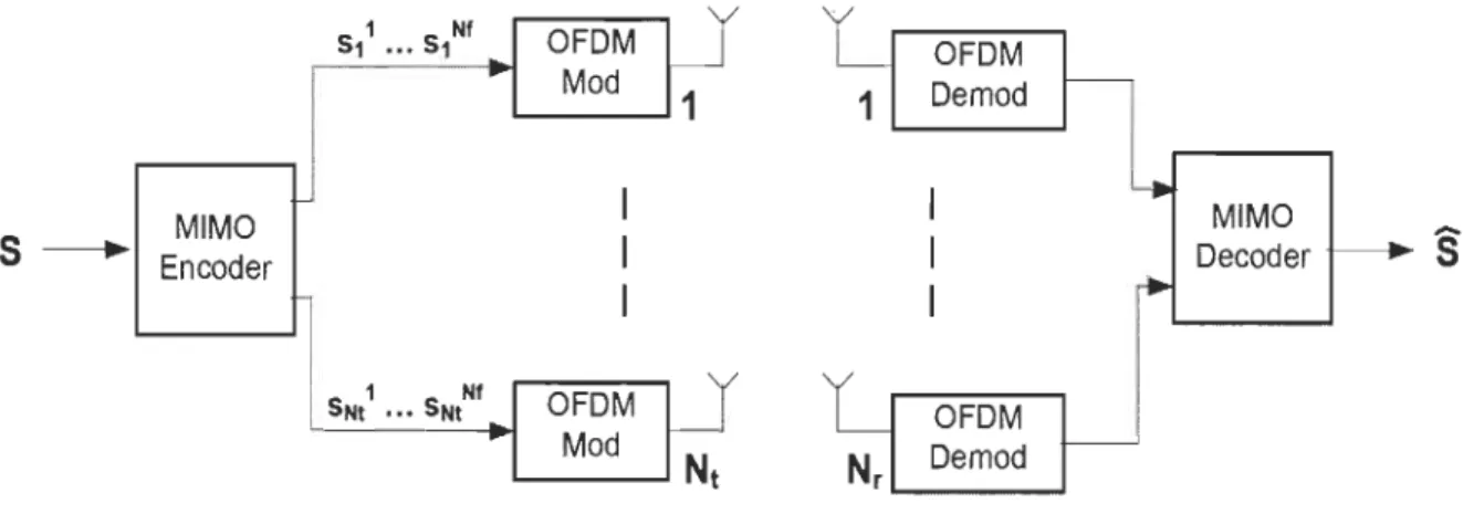
Figure 2-6. The basic idea of using MIMO-OFDM signaIs is to ensure that the quality of signal (measured by BER) and data rate (bits/sec) are improved. This is done by combining the signaIs on the transmit (TX) antennas at one end and the receive (RX) antennas at the other end. The result improvements in terms of link quality and performance can be used to significantly increase the operator's revenue as well as the wireless network quality of service.
MIMO Encoder S11 ••• S1Nf OFDM
0
r Mod 1 1 1 i 1 1 ! 1 Nf SNt ••• SNt OFDM Mod' - - - -.... Nt
OFDM 1 Demod Nr OFDM Demod ' - - - _...
MIMO DecoderFigure 2-6 Simplified block diagram of MIMO-OFDM system A general MIMO-OFDM system is shown in
Figure 2-6, where Nt transmit antennas, Nr receive antennas, and Nrtone OFDM are used. First, the incoming bit stream is mapped into a number of data symbols via sorne modulation type such as BPSK. Then a block of Ns data symbols [Si' S2, " " , , SNJ are encoded into a codeword matrix S of size TXNt which will then be sent through Nt antennas in T OFDM frames, each frame consisting of Nf sub-channels. Specifically, SJ, SI, " " SJ will be transmitted from the
/h
transmit antenna in OFDM frames 1,2, "" " T respectively, whereS'j
denotes a vector of length Nf, for aIl j = 1,2,." ", Nt andn
= 1,2"", , , T The codeword matrix S can be expressed as.(2.6)
After appending the cyclic prefix on each OFDM frame,
Sj
will be transrnitted from the/h
transmit antenna in then
th OFDM frame.We can identify X of size Nf x Nt as a subset of S that represents the transmitted symbols from aU transmitting antennas for the duration of one OFDM frame, hence
(2.7)
Or it could be written as
(2.8)
Here xy=l:N r) is a vector represents aU symbols transmitted from antenna
j
through aU Nfsubcarriers.
After passing through the MIMO channels, the received signaIs will be first sent to the reverse OFDM frame (cyc1ic prefix removal and FFT) and then sent to the decoder.
The received vector could be represented as y(k=l:Nr)
1 y(k=l:Nr)
2
(2.9)
Wit1;lOut loss of generality, we can consider only one subcarrier (k=1), then equation 2.9 can be represented in a matrix form as
Y=HX+v (2.10)
Where Y is the received vector with Nr dimension, H is an NrxNt complex propagation matrix that is assumed constant for the length of a frame transmission (i.e., a quasi-static channel) and assumed known at the receiver (e.g., via transmission of training sequences). It is
assumed that the statistics of the channel transfer matrix H can be described by the fading statistics namely, Rayleigh fading, Ricean fading or AWGN. Furthermore, it is assumed that the elements of H have a variance of one, or, in other words, the average channel gain Pc is normalised to one.
2.2.5 MIMO Detection techniques
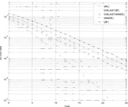
This section summarizes and compares the various algorithms designed to detect the MIMO signaIs, Channel State Information (CS!) is assumed to be perfectly known at the receiver side. A few examples of such algorithms include Maximum-Likelihood (ML) algorithm, the Zero-forcing (ZF) algorithm, the Minimum Mean Square Error (MMSE) algorithm, and the V-BLAST algorithm.
2.2.5.1 Maximum-Likelihood (ML)
The ML algorithm uses a received vector Y to detect the vector symbol most likely to be transmitted by the transmitter. Minimizing the difference between the transmitted signal affected by the channel coefficients and the received signal is done by using the following equation:
The number of transmitting and receiving antennas plays an important role in defining the
size of possible number of input vector 2NtNr that need to be checked using the ML algorithm.
If we consider the number of transmitting and receiving antennas as 2 with BPSK modulation,
the total likely candidates turn up to be 22*2=16 different signaIs. When the number of
transmitting and receiving antennas becomes 4, the number of candidates becomes 24*4=65536
different signaIs.
2.2.5.2
Zero Forcing (ZF)
The ZF aigorithm gives its best results when Inter Signal Interference (ISI) becomes
prominent in the performance of the system. The interference is cancelled out by the
introduction ofweight matrix into the system. By multiplying the NtxNr weight matrix with the
incoming signal at the receiver, we can get an estimated transmitted signal as shown in the
equation.
(2.12)
This detection technique is aiso known as spatial filtering. The condition Nt ~ Nr should be
maintained true in order to perform this linear demultiplexing. The simple process of ZF filtering is described in the following steps.
A weight vector of Nr dimensions w~f.k' for the kth transmitted substream is given by
(2.13)
In which, the Moore-Penrose (MP) inverse is denoted by the '+' symboi and an Nt
The product of H+ with
gr
gives the kth row vector in the H+. Assuming that Nt ~ Nr asmentioned above, the pseudo inverse code of H is computed using
(2.14)
The weight matrix needed to calculate aU transmitted substreams could be obtained by
applying the MP pseudo inverse matrix H+ as
(2.15)
we could choose inverse schemes other than MP pseudo inverse. The reason for choosing
MP pseudo inverse in ZF is to obtain a norm-minimized and least-squares-type weight vectors.
When the transmitted signal Y(t) is multiplied with Wz{ , the output vector signal(Nt
-dimensional) is denoted by
S
= WzfY (2.16) (2.17) = X+
Wzfv (2.18)[
T l
WZ{.l V=x+
:
W~{.Nt v
(2.19)The ZF algorithm reduces the power of the interfering substreams to zero. This results in
maximizing the SIR (Signal to Interference power Ratio) in the filtered output signal. As the
power of received signal is sacrificed, ZF algorithm provides lower SNR compared with other
2.2.5.3 Minimum Mean Squared Error (MMSE)
The ZF algorithm doesn't consider the effect of noise in the channel while reducing the interference. This results in increasing the noise power in the desired signal, which causes degradation in the output signal quality. This deficiency is addressed in the MMSE (Minimum Mean Squared Error) algorithm. As the name suggests, this algorithm minimizes the error
between the output signals(t) and a reference signal (t) . The Mean Square Error J(w) is shown as
J(w)
=
E[ld -s12]
(2.20)(2.21) (2.22) In this equation, E[ *] denotes the ensemble average (expectation) of the signal. y rd & Rrr
respectively represent the correlation vector and the correlation matrix. They are defined using the equations
Yrd = E[y*d]
At the minima ofJ(w), the following condition holds true.
JJ(W) = 0
Jw
(2.23) (2.24)
(2.25)
Using differentiation for (2.22 ) with respect to w, we can arrive at the following conditions shown below.
a(T * )_O
aw
W Yrd-By substituting (2.22) and (2.26)-(2.28) into (2.25), we can obtain
this brings us to the resulting equation
R -1
w
mmse = rr Yrd (2.26) (2.27) (2.28) (2.29) (2.30) The vector derived from the above equation is the weighted MMSE vector for a single substream. When it is generalized to a system ofNtxNr, we get the equation(2.31)
W~mse is the matrix of size NtxNr, and Yrdrepresents the correlation matrix in the received
signal caLculated by the received signal vector Y and an Ntxl dimensional reference signal vector D using the equation
Yrd = E[Y* XT] (2.32)
By defining the Pt as the average transmission power per antenna, we can represent the correlation vector as well as correlation matrix using the equations (2.23) & (2.24), as follows.
(2.33)
In the above equation a2 represents the power of thermal noise and 1 Nrdenotes a unit matrix of size Nr .
The optimal matrix W mmse can be derived as follows.
WT R-1 mmse
=
rrYrd (2.35) 2 -1 =2:..
Pt (H*HT+
~1
Pt NT ) P Ht * (2.36) 2 -1=
(H*HT+~1
Pt NT)
H* (2.37)Therefore, the optimum MMSE weight matrix is obtained by
(2.38)
(2.39)
As the MMSE algorithm takes the thermal noise into consideration, it improves the signal power of the desired component in order to improve the SNR performance of the system.
r----1 r---~ L -_ _ - ; _ _ ~---~~---~--~j :
---2.2.5.4 VBLAST 1 1 1 1 1 t 1 1 1 1 1 1 : ~ _______ ______________________ J 1st stage • 1 st detected substream-•
-j 1,
1 1,
1 1 1 1 1 1 1 1 1 2nd stag.e - --1 1 1,
1 1 j 1 t 1~---J
;~~~-~tected
substream Figure 2-7 SIC architecture modelThis nonlinear algorithm is very popular due its usage of SIC (Successive Interference Cancellation) depicted in the Figure 2-7. One of the above described algorithms (ZF or MMSE) is useful in detecting the strongest component in the received signal that will be used for interference cancellation. VBLAST uses the strongest signal detected at the receiving end and subtract it from the received signal. It then proceeds to the detection of the second most powerful signal, since it has already cleared the first and so forth. The final vector is provided after aIl interferences added in the channel are cancelled.
SIC-ZF
This section gives an initial description of the SIC algorithm when it is combined with the ZF method. This combination is known as VBLAST architecture. Using Ci' as an indicator for the ith iteration, we can work on the following equations.
(i)
Wzf,k = WZf,k (2.40)
y(i) = y (2.41)
(2.42) Symbols in the first stage, or those with (i=l), are given as follows:
(1)
Wzf,k
=
WZf,k (2.43)y(l) = y (2.44)
(2.45)
By assuming that WZf,k has the smallest normalized vector, we estimate the vector
Xk
l) withthe help of ZF spatial filter
Xk
l) for the kth substream of the output. This estimated vector is cancelled from the signal vector y(l) by using its corresponding channel vector hk.(2.46) Using this method for aIl the corresponding vectors in the channel matrix, we arrive at the
following conclusions. H (l) =
Ih
l ... hk-lhkhk+l ... hNtl Nt colum vectors H(2) =Ih
l ... hk-lhk + l .. , hNtl Nt-l colum vectors (2.47) (2.48)The above process converts the size of the channel matrix to Nr x Nt - 1. The MP pseudo
which is used to estimate the !th substream of the signal. By using the minimum vector, we can cancel hl and X~2) from H(2)and y(2) respectively, which gives us the following equations.
H(2) = Jhl ... hl - 1hlhl+1 ... hNt-l1 Nt-1 colum vectors H(3)
=
Ih1 ... hl - 1hl+1'" hNt-11 Nt-2 colum vectors (2.49) . (2.50) (2.51)This procedure is iterated Nt times in order to find the complete estimate of the received signal. The spatial diversity is increased as we progress through the detection stages; hereby SIC-ZF gives better performance than the traditional ZF algorithm.
2.2.5.5 SIC-MMSE
The performance of SIC could be further improved when MMSE is used instead of ZF because the former algorithm maximizes the output SNR (Signal to Noise Ratio). When SIC uses MMSE for substream separation, it is called SIC-MMSE. Although the process is similar to that of SIC-ZF, it differs when the substream quality is evaluated. the SIC-MMSE gives better spatial diversity than the SIC-ZF for an equal number of antennas.
In Figure 8 the performance of each MIMO detection algorithm is simulated for 2-transmit and 2- receive antennas using BPSK modulation. Although the ML is the most
complex than any other algorithms, it has the best performance; the results also show that nonlinear SIC algorithms with either ZF or MMSE gives better performance than linear algorithrns such as ZF and MMSE.
- - ""(ML) (VBLAST-ZF) ~ '""" "(VBLAST-MMSE) "(MMSE) - - 1 -"2 10 ;:=.. --r- "" -r - - - f---
----t-
-cr- -- 1--r- " ~" ""-i
"
- 1-- - 1-- - ri -~ " ~I-~ - -"- --f--e- l - t - - - r--- - 1 - - - --lJ
' - - - ~ ~ 10 15 20 25 SNRFigure 2-8 Performance comparison for MIMO detection algorithms (2 Tx, 2Rx and BPSK modulation)
2.3 MIMO-OFDM coding techniques
The performance and capacity of a communication system depends on the structure of the transmission side as much as it depends on the channel condition. The complexity of the transmitter as well as the receiver depends on the transmitted signal design. This particular fact has guided the direction of various researches into the design of suitable MIMO co ding techniques. These schemes of coding can be divided into two broad categories: Space Time Coding (STC) and Space Division Multiplexing (SDM). The advantage of STC lies in its ability to increase the robustness of the system, while SDM increases the maximum data rate attainable by the system. STC improves the robustness by using different antennas to transmit the coded symbols over different sub-carriers, while SDM uses a single sub-carrier to transmit independent data streams over different branches. These approaches can be combined in order
to obtain various types of transmission schemes and give a number of options for the systems designer to choose from. The choice depends on various pararneters such as bit-error-rate of the channel, sensitivity to channel/interference, computational complexity/simplicity and overall performance of the system. The classification of MIMO-OFDM systems using various algorithms based on the above schemes could be summarized as follow.
Open-Ioop versus closed-Ioop techniques:
In open loop transmission schemes the wireless communication systems assume no
knowledge of the channel response at the transmitter. On the other hand, the closed loop systems provide the channel information back to the transmitter side by using sorne kind of feedback mechanism. The information provided via feedback is used to select proper structure of the transmitted signal, i.e. the transmitted power per antenna, coding rate, type of space-time mapping, and/or constellation size.
Transmit diversity versus spatial multiplexing algorithms:
In a richly scattered environment, transmit diversity plays an important role to maintain the robustness of the wireless communication system. Transmission schemes that exploit MIMO diversity use spatial dimensions to add more redundancy, thus keep the data rate equivalent to SISO system in order to increase the BER performance. Space-Time Coding is the principal of generating redundancy by coding across time and spatial dimensions. On the other hand, Space Division Multiplexing (SDM) is employed if the algorithm uses different antennas to transmit multiple data symbols over the channel. SDM scheme is used if high data rates are the main objective of the system. These schemes are not mutually exclusive in nature, and therefore are used in different combinations to produce hybrid schemes that combine transmit diversity and spatial multiplexing and partly benefit from both robustness and data rate enhancement.
Theoretical analysis for the trade-off between diversity gain and Spatial Multiplexing gain was carried out in [38], and an example was given in [15].
Joint Coding (JC) versus Per-Antenna Coding (P AC):
In MIMO system Joint Coding or vertical coding [39] refer to the transmission scheme where the bit stream is encoded first and then separated into different sub-streams of which each is modulated and mapped onto the corresponding transmit antenna. On the other hand, in Per-Antenna coding (or vertical coding) the bit stream is first divided into different sub streams, which are coded with separate codes and then modulated for transmission from the transmission antennas [40]. The first method uses the time and space dimensions to produce redundancy and improve the performance of the signal, while the P AC simplifies the receiver architecture due to the separate encoding provided for the spatial and time dimensions.
The combination of the above transmission approaches result in many possible transmission schemes, which cater for aU the needs of communication systems. Various parameters like capacity performance, bit error-rate performance, computational complexity/simplicity and output SNR vary from one scheme to another resulting in a wide range of trade-offs that need to be considered. An overview of sorne standard MIMO transmission techniques is given in the next subsections.
2.3.1 Space-Time codee! MIMO-OFDM
The Space-Time coding techniques use the space and time dimensions to code the message data symbols. The resulted transmission scheme exploits the spectral efficiency of the MIMO system by adding more redundancy in order to improve robustness. In order to code the signal over space and time dimensions without compromising its efficiency, the criteria defined in [52]