Introduction
Biomechanical testing of functional spinal units (FSUs) is used extensively to better understand the kinematics and the kinetics of the intact and instrumented human spine [17]. There is a long-lasting controversy regard-ing the choice of the system to reproduce the physio-logical behavior of an FSU for biomechanical tests. Although the fully unconstrained system is developing into the ‘‘gold standard’’, it remains unclear how the mechanical behavior is affected by the introduction of
the limited number of constraints associated with multiple degrees of freedom (DOF) servohydraulic testing systems.
Some biomechanical studies are conducted using unconstrained systems [3–5,7,11,14,20,21,24,26,29–
31], whereas others are using constrained systems [2, 8,
15, 16, 19, 31]. Among all these studies, only one [13] attempted to compare the mechanical behavior between an unconstrained and a partially constrained system on the same intact FSU. The purpose of such systems are to characterize the three-dimensional mechanics of FSUs E. A. Charriere T. Beutler M. Caride P. Mordasini T. E. Orr P. K. Zysset
Compliance of the L5-S1 spinal unit: a
comparative study between an unconstrained
and a partially constrained system
Received: 15 August 2002 Accepted: 30 July 2004 Published online: 30 April 2005 Ó Springer-Verlag 2005
Abstract A comparison between an unconstrained and a partially con-strained system for in vitro biome-chanical testing of the L5-S1 spinal unit was conducted. The objective was to compare the compliance and the coupling of the L5-S1 unit mea-sured with an unconstrained and a partially constrained test for the three major physiological motions of the human spine. Very few studies have compared unconstrained and partially constrained testing systems using the same cadaveric functional spinal units (FSUs). Seven human L5-S1 units were therefore tested on both a pneumatic, unconstrained, and a servohydraulic, partially con-strained system. Each FSU was tes-ted along three motions: flexion-extension (FE), lateral bending (LB) and axial rotation (AR). The ob-tained kinematics on both systems is
not equivalent, except for the FE case, where both motions are simi-lar. The directions of coupled mo-tions were similar for both tests, but their magnitudes were smaller in the partially constrained configuration. The use of a partially constrained system to characterize LB and AR of the lumbosacral FSU decreased sig-nificantly the measured stiffness of the segment. The unconstrained system is today’s ‘‘gold standard’’ for the characterization of FSUs. The selected partially constrained method seems also to be an appro-priate way to characterize FSUs for specific applications. Care should be taken using the latter method when the coupled motions are important.
Keywords Biomechanics Æ Spine Æ Kinematics Æ
Torque Æ Degree of freedom
E. A. Charriere (&) Æ M. Caride P. K. Zysset
Mechanical Engineering Department, Laboratory of Applied Mechanics and Reliability Analysis,
Swiss Federal Institute of Technology, Lausanne, Switzerland E-mail: eric.charriere@hispeed.ch E. A. Charriere Æ P. Mordasini Hoˆpital Orthope´dique de la Suisse Romande, Lausanne, Switzerland T. Beutler Æ T. E. Orr
M.E. Mu¨ller Institute for Biomechanics, University of Bern, Bern, Switzerland E. A. Charriere
Les Bosquets de Paudille 5, 1803 Chardonne, Switzerland
or multi-segmental samples [11, 26], as well as to test implants and fixations devices for the spine [1, 6, 8, 10,
20,23,31].
Unconstrained systems are designed to let the tested segment completely free to move and rotate along the six DOF of a rigid body. Pure torque being applied, the segment will follow a free pathway to its stable position and rotate around its ‘‘own’’ rotation axis. Coupled motions occur, especially for boundary conditions breaking the sagittal plane of symmetry, such as lateral bending (LB) and axial rotations (ARs). This testing method is appropriate to characterize the three-dimen-sional motion of the L5-S1 FSU.
Constrained systems do not let the segment move and rotate along the six DOF. These systems restrict motions along certain direc tions and some additional forces/ torques are therefore produced. The center of rotation is constrained and is not allowed to move freely according to the samples’ geometry and to the studied loading case (i.e., injured and stabilized segment). The main advan-tage of such systems is the simplicity of applying loads or displacements with universal materials testing machines. We define partially constrained systems as con-strained-like systems with more than zero DOF, but with less than six DOF (as for the fully unconstrained system). With such systems it is possible to apply loads or displacements in a specific direction and to control loads or displacements in the others. New laboratory servohydraulic equipment allows this combination of such forces and displacements and is less sensitive to the positioning of the center of rotation than fully con-strained systems. Coupling can also occur and be mea-sured with such systems. Their main advantages are the possibility to control torques, forces, angles and dis-placements in multiple directions and to apply dynamic boundary conditions to the tested segment.
This study does not intend to compare the accuracy of load-controlled versus displacement-controlled spine testing system to the in vivo case [14, 27, 28]. A good review has been made concerning this point by Goel et al. [12]. The purpose of the present study is to compare the compliance curves of the lumbosacral FSU measured with a partially constrained system and an unconstrained system using the same anatomical specimens.
Materials and methods
Seven fresh human cadaveric L5-S1 FSUs (four male, three female, average age 79 years) were obtained in agreement with the ethics regulations of the affiliated hospital. CT scans and radiographs of the specimens did not show the presence of osteophytes, endplate sclerosis or disc space narrowing beside normal degenerative changes. All non-ligamentous soft tissues were removed before mounting the FSUs in polymethylmethacrylate
(PMMA) blocks. FSUs were wrapped with water-soaked cloth, put in a plastic bag and kept in a freezer at )25°C. The night before testing, they were left to thaw at ambient temperature.
The FSUs were tested in flexion-extension (FE), bilateral AR and bilateral lateral bending (LB) using first an unconstrained (custom designed, also used for the study by Grassmann et al. [13]) and then a partially constrained system (MTS, Minneapolis, Minn., USA). The former system (Fig.1a) involved the application of stepwise unconstrained pure moments (0, 2.5, 5, 7.5 and 10 Nm) on L5 in the principal motion direction, allowing motion along six DOF that was quantified using an optoelectronic camera (Northern Digital, Waterloo, Ontario, Canada). S1 was fixed and unable to move. This procedure was repeated three times and data were re-corded during the last cycle. The segment was left creeping for 1 min between each moment increment. According to Panjabi et al. [24], a flexibility protocol has been used for this configuration. The latter was a com-mercial multiaxial system (Fig.1b), which allowed the control of a maximum of three DOF. This system is called the ‘‘partially constrained system’’ in this paper. For each specimen, the Cardan angles measured with the uncon-strained system were used as an input for the subsequent measures with the partially constrained system.
For the FE motion, FE angles were applied, axial torque and axial force being strictly kept to zero. For the LB motion, bilateral LB angles were applied, axial tor-que and axial force being strictly kept to zero. Finally, for the AR motion, bilateral AR angles were applied, axial force being strictly kept to zero. All other motion directions were fixed. The specimens were positioned on and aligned to the systems with frontal and lateral X-ray radiographs.
For the sake of direct comparison between the two experiments, it is necessary to characterize the nonlinear compliance curves by some variables. Stiffness is calcu-lated as the slope of the observed linear part of the compliance curve (between 2.5 and 10 Nm) and the neutral zone by its intersection with the angle axis. For a type of motion (e.g. an unconstrained flexion) all experimental data of the seven specimens are also fitted with a two-parameter power law (Eq. 1).
Angle¼ a: Torquej jb ð1Þ
Angle decomposition
In order to compare these two testing methods as accurately as possible, it is necessary to express the variables in the same reference system. The goal of this work being to quantify the movement of L5 compared with S1, a reference system is associated with each
vertebra and the relative movement of the one compared to the other will be measured or calculated according to the experimental method used.
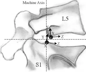
The origin of the reference system associated with L5 is the inferioposterior point of the average sagittal plane of the vertebral body. For S1, the vertebral body being more difficult to distinguish individually, since it is fused with the different sacral vertebrae, the origin of the reference system is located at the superioposterior point of the average sagittal plan. For the two systems of axes, the X axis is directed towards the left and it is perpen-dicular to the sagittal plan. The XZ plan selected was defined parallel to the lower endplate of the vertebral body of L5, respectively the upper endplate of that of S1. Figure2shows a schematic sagittal representation of the segment and its associated reference systems.
All rigid body motions have been described in three axis rotations and one translation using the ZYX Car-dan angle decomposition.
Helical axis of rotation
The motion of a rigid body may be expressed with a unique rotation about and a unique translation along a particular axis [33]. The axis along which the object translates and rotates is called the helical axis (or screw axis). This representation of a joint motion is very useful in order to understand and compare complex motions, such as joint movement. It is therefore possible to compare the helical axis of rotation of a joint and the translation of the bones involved in a joint. The math-ematical helical decomposition of such angle and translations used in this study was done according to Kinzel et al. [18]. Considering the helical axis, the helical angle is defined as the angle measured around this axis
and the helical torque is the projection of the torque on this axis. Helical stiffness is calculated as the slope of the observed linear part of the helical compliance curve (helical angle versus helical torque) and the helical neutral zone by its intersection with the helical angle axis.
Statistical analysis
Statistical comparisons between the unconstrained and the partially constrained results were conducted using the two-sample Wilcoxon signed rank test. Significance was attributed to P values below 0.05.
Fig. 1a,b Picture of mechanical test set-ups. a Unconstrained system in the FE configuration with a L5-S1 FSU (1). Pulleys (2) are used to apply a pure torque. The upper PMMA block (3) is free to move in all directions. Eight active infrared light-emitting diodes (4) en-abled the measurement of the three-dimensional relative mo-tion. b Partially constrained system in the FE configuration with a L5-S1 FSU (1) embed-ded in PMMA (2). The MTS multiaxial servohydraulic sys-tem (3) allows the application of controlled torque, force, dis-placement or angle
Fig. 2 Schematic sagittal representation of the segment and its associated reference systems
Results
Figure3shows all obtained angle-torque curves as well as the mean flexibility fitted power laws for all segments and all motion types on both systems. These fitted curves are compared with the results obtained by Pan-jabi et al. [26]. The two coefficients of the power law are presented in Table 1for all motions. In order to simplify the presentation of the results, coupled motions are not shown in this paper. The coupled motions measured on the unconstrained system agree with those found by Panjabi et al. [26]. The directions of coupled motions, which are allowed to occur on the partially constrained system, were similar for both set-ups, but the magni-tudes were smaller in the partially constrained configu-ration, especially in axial torsion and LB. The largest motion and neutral zone occur in flexion. In AR, the neutral zone is the smallest and stiffness the largest compared with the other motions.
For FE (Fig. 3a), stiffness did not show significant differences between both methods (Fig. 4). Furthermore, directions and magnitude of the allowed coupled mo-tions were similar. No significant differences were found between unconstrained and partially constrained neutral zones (Fig. 5, P=0.15 for flexion and P=0.28 for extension motion). Considering AR (Fig.3b), a signifi-cant difference in stiffness (P=0.047) was found between the unconstrained and partially constrained methods. The unconstrained principal motion was 26% stiffer than the partially constrained one. No significant dif-ferences were found between unconstrained and par-tially constrained neutral zones (P=0.81). Finally, considering LB (Fig.3c), more significant differences in both stiffness (P=0.015) and neutral zone (P=0.016) were found. The unconstrained principal motion was 53% stiffer than the partially constrained one. The unconstrained neutral zone was 6% larger than the constrained one.
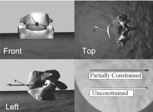
For FE, there is also no significant difference between helical stiffness (P=0.22 for flexion and P=0.25 for extension). In flexion, the helical neutral zone is 15% larger for the unconstrained compared with the partially constrained system (P=0.015). In extension, no signifi-cant differences have been observed (P=0.31). For bilateral axial rotation, there is also no significant dif-ference between helical stiffness on both systems (P=0.25). The helical neutral zone is 56% larger for the unconstrained compared with the partially constrained system (P=0.006). For bilateral LB, the helical stiffness is 35% larger for the unconstrained compared with the partially constrained system (P=0.0398). The helical neutral zone is 52% larger for the unconstrained com-pared with the partially constrained system (P=0.0005). The helical axis averaged over the seven FSUs of the left lateral bending (motion which gave the most
impor-Fig. 3 Compliance curves for FE (a), bilateral axial rotation (b) and bilateral LB (c). They were fitted with the four experimental data for each experiment and for each motion and compared with the study of Panjabi et al. [26]
tant differences in the stiffness and neutral zones between both systems) is shown on Fig.6for both systems. The unconstrained helical axis of rotation differs extensively from the partially constrained set-up, as coupled motions are more important on the former system.
Discussion
Despite the advanced age of our anatomical specimens, the principal flexibility curves obtained with the unconstrained method in FE, AR and LB were consis-tent with previous data [26]. The FE motions depend extensively on the disk material properties and stiffness of these disks increases with age. Therefore, it seems reasonable that our elderly segments are somewhat stiffer than the one tested by Panjabi et al. [26] for the FE motion. By contrast, the range of motion in axial rotation is dominated by the presence of the facets and in particular of the remaining thickness of cartilage [9], which may explain the increased laxity of our aged segments when compared with the ones measured by Panjabi et al. [26].
The partially constrained method appears to provide the same FE behavior as the unconstrained method. Since the coupled translations are comparable, the par-tially constrained set-up could therefore be used as an alternative to the unconstrained one for this particular motion. As a result, dynamic testing of L5-S1 segments could be envisaged for the FE motion type. However, a precise placement of the axis of rotation is recommended in order to keep the results comparable. According to the studies of Panjabi et al. [25] and Haher et al. [16], the axis of rotation is located around the vicinity of the posterior longitudinal ligament, near the posterior point of the average sagittal plan of the vertebral body (as used in this study and shown in Fig.2). These authors claim that changing the position of the axis of rotation has a pro-found effect on the flexibility curve of the tested FSU.
The position of the axis of rotation was found to be nearly equivalent on the two mechanical set-ups for the FE motion. As coupling is negligible for such move-ment, the axis of rotation is almost perpendicular to the sagittal plane. Differences between the sagittal locations (YZ plan) of the axis do not exceed 15 mm. The differ-ence is mainly due to the positioning of the segment on the partially constrained machine. For such a system, aligning the sagittal machine axis to the average plan of the disk and the longitudinal machine axis to the supe-rioposterior point of the average sagittal plan of S1 will shift the axis of rotation posteriorly and cranially. For the unconstrained system, fixing S1 to the table and let only L5 move will shift the axis of rotation caudally. Despite these dissimilarities between the results obtained on both systems, the mechanical behavior of the segment is comparable. Trying to characterize the mechanical behavior of injured segments or segments with fixations or implants with the partially constrained system for the
Fig. 4 Box–whisker plots of stiffness compared between both systems. The boxes represent the upper and lower quartiles, whereas the whiskers show the maximum and minimum values. Significant differences are designed by an asterisk after the P value
Fig. 5 Box–whisker plots of the neutral zone compared between both systems. The boxes represent the upper and lower quartiles, whereas the whiskers show the maximum and minimum values. Significant differences are designed by an asterisk after the P value Table 1 Coefficients and associated standard deviations of the
power law (Eq. 1) for all motions on both systems. The results for the unconstrained system are printed in italics
Flexion Extension Bilateral axial rotation Bilateral lateral bending Abs(a) 3.65 ± 1.26 2.38 ± 0.78 0.61 ± 0.39 1.53 ± 0.56 4.12± 1.03 2.16± 0.47 0.65± 0.48 1.46± 0.66 b 0.27 ± 0.06 0.37 ± 0.10 0.56 ± 0.12 0.44 ± 0.12 0.21± 0.05 0.33± 0.04 0.51± 0.19 0.39± 0.11
FE motion may increase the difference between the re-sults found on both systems. The natural axis of rotation may shift with these new conditions and additional forces may be generated in the partially constrained configuration.
The use of a partially constrained system to charac-terize lateral bending and, to a lower extend, AR of the lumbosacral FSU decreases significantly the measured stiffness. Given the rigorously controlled testing condi-tions, this behavior cannot be attributed to damage or tissue degradation and was previously observed by Grassmann et al. [13] in AR of lumbar FSUs. It was shown that coupled motions tended to restrict the principal motion of lumbar FSUs. Constraining the segment reduces the coupled motions and decreases the principal stiffness. It is not easy to conceive why the stiffness increases with the number of free DOF on the testing set-up because the opposite would be true for a linear system
As the helical axis (for the whole motion) is not ori-ented and positioned identically in the two configura-tions, the FSU is tested along two quite distinct motions. The helical decomposition tends to decrease the differ-ences between stiffness, because all motions are taken into account in this case (main motion + coupled mo-tions). On the one hand, the mean stiffness of the FSUs tested on the partially constrained system for the bilat-eral LB remains almost constant, independently of the used decomposition (7.5 Nm/deg in the Cardan decomposition and 7.7 Nm/deg in the helical decom-position). On the other hand, the mean stiffness of the
FSUs tested on the unconstrained system for the same motion decreases from 9.5 Nm/deg in the Cardan decomposition to 7.0 Nm/deg in the helical decomposi-tion. In the partially constrained configuration and in the LB case, the helical neutral zone and stiffness remain smaller than in the unconstrained configuration. Fur-thermore, differences in the mean axis of rotation posi-tion averaged over the seven FSUs (22 mm for the bilateral AR in the XZ plan and 25 mm for the bilateral LB in the XY plan, both laterally) is larger than for the FE motion and are mainly due to the large amount of coupling for such motions. Consequently, the decrease in stiffness associated with the constrained loading path must be intrinsic to the geometrically and materially non linear mechanical behaviour of the lumbosacral FSU and should be confirmed by the use of a finite element model including the joint facets with the corresponding boundary conditions.
Combining this study with the one conducted by Grassmann et al. [13] provides new information on the flexibility of the lumbosacral FSU and the related testing methods. As found for the completely constrained axial rotation [13], we have found that constraining the seg-ment decreases its stiffness. The same results have been found for LB, and the decrease of the stiffness was even more pronounced. While the softening mechanism en-forced by the constrained boundary conditions remains unknown, this novel property associated with the nonlinear behaviour of the FSU may become of signif-icance for in vivo loading in healthy and/or degenerative condition.
Fig. 6 Standard views of the helical axis for the left lateral bending. The arrows indicate the negative helical rotation
For the FE motion, both constrained and uncon-strained systems are comparable, and both could therefore be used for the characterization of intact FSU. Trying to characterize the mechanical behavior of in-jured segments or segments with fixations or implants with the partially constrained system for the FE motion may increase the difference between the results found on both systems. The natural axis of rotation may shift with these new conditions and additional forces may be generated in the partially constrained configuration.
Conclusions
According to our findings, particular care should be given when quantifying and comparing the kinematics of
the intact or instrumented spine with experimental set-ups of various degrees of constraints for AR and to an even larger extent for LB. The obtained kinematics on the investigated unconstrained and commercially avail-able partially constrained systems is not equivalent; i.e., the segment does not follow the same pathway to the equilibrium positions, except for the FE case, where both motions are similar. Furthermore, as in vivo boundary conditions are mixed conditions (i.e., torques and forces, rotations and translations are simultaneously imposed to various parts of the segment) that are not well identified, it remains difficult to impose realistic boundary conditions to the segment in vitro.
Acknowledgements This work is supported by the ‘‘Hoˆpital Orthope´dique de la Suisse Romande’’.
References
1. Abumi K, Panjabi MM, Duranceau J (1989) Biomechanical evaluation of spinal fixation devices. Part III. Stability provided by six spinal fixation devices. Spine 14:1249–1255
2. Adams M, Hutton W (1981) The rele-vance of torsion to the mechanical derangement of the lumbar spine. Spine 6:241–248
3. Ahmed AM, Duncan NA, Burke DL (1990) The effect of facet geometry on the axial torque-rotation response of lumbar motion segments. Spine 15:391– 401
4. Andersson GBJ, Schultz AB (1979) Ef-fects of fluid injection on mechanical properties of intervertebral discs. J Biomech 12:453–458
5. Asazuma T, Stokes IAF, Moreland MS et al (1990) Intersegmental spinal flexi-bility with lumbosacral instrumenta-tion: an in vitro biomechanical investigation. Spine 15:1153–1158 6. Ashman RB, Birch JB, Bone LB et al
(1988) Mechanical testing of spinal instrumentation. Clin Orthop 227:113– 125
7. Boden SD, Martin C, Rudolph R et al (1994) Increase of motion between lumbar vertebrae after excision of the capsule and cartilage of the facets-a cadaver study. J Bone Joint Surg Am 76:1847–1853
8. Brodke DS, Dick JC, Kunz DN et al (1997) Posterior lumbar interbody fu-sion—a biomechanical comparison, including a new threaded cage. Spine 22:26–31
9. Charrie`re E (2002) A calcium phosphate implant with controlled macroporosity for anterior L5-S1 interbody fusion. Ph.D. Thesis No. 2507, EPFL-Lau-sanne
10. Edwards WT (1991) Biomechanics of posterior lumbar fixation. Analysis of testing methodologies. Spine 16:1224– 1232
11. Goel VK, Goyal S, Clark C et al (1985) Kinematics of the whole lumbar spine: effect of discectomy. Spine 10:543–554 12. Goel VK, Wilder DG, Pope MH et al
(1995) Controversy: biomechanical testing of the spine. Load-controlled versus displacement-controlled analysis. Spine 20:2354–2357
13. Grassmann S, Oxland TR, Gerich U et al (1998) Constrained testing condi-tions affect the axial rotation response of the lumbar functional spinal units. Spine 23:1155–1162
14. Gunzburg R, Hutton W, Fraser R (1991) Axial rotation of the lumbar spine and the effect of flexion. Spine 16:22–28
15. Haher TR, O’Brien M, Dryer JW et al (1994) The role of the lumbar facet joints in spinal stability: identification of alternative paths of loading. Spine 19:2667–2671
16. Haher T, O’Brien M, Felmly WT et al (1992) Instantaneous axis of rotation as a function of the three columns of the spine. Spine 17 (Suppl):S149–S154 17. Kim YE, Goel VK (1990) Effects of
testing mode on the biomechanical re-sponse of a spinal motion segment. J Biomech 23:289–291
18. Kinzel GL, Hall AS, Hillberry BM (1972) Measurement of the total motion between two body segments-I analytical development. J Biomech 5:93–105 19. Kunz DN, McCabe RP, Zdeblick TA
et al (1994) A multi-degree of freedom system for biomechanical testing. J Biomech Eng 116:371–373
20. Lund T, Oxland TR, Jost B et al (1998) Interbody cage stabilization in the lumbar spine. J Bone Joint Surg Br 80:351–359
21. Nachemson AL, Schultz AB, Berkson MH. Mechanical properties of human lumbar spine motion segments: influ-ence of age, sex, disc level, and degen-eration. Spine 4:1–8
22. Oxland TR, Crisco JJ III, Panjabi MM et al (1992) The effect of injury on rotational coupling at the lumbosacral joint. A biomechanical investigation. Spine 17:74–80
23. Panjabi MM (1988) Biomechanical evaluation of spinal fixation devices: 1. A conceptual framework. Spine 13:1129–1134
24. Panjabi MM, Brand RM, White AA (1976) Three-dimensional flexibility and stiffness properties of the human tho-racic spine. J Biomech 9:185–192 25. Panjabi MM, Kato Y, Hoffman H et al
(2000) A study of stiffness protocol as exemplified by testing of a burst fracture model in sagittal plane. Spine 21:2748– 2754
26. Panjabi MM, Oxland TR, Yamamoto I, et al (1994) Mechanical behavior of the human lumbar and lumbosacral spine as shown by the three-dimensional load-displacement curves. J Bone Joint Surg Am 76:413–424
27. Pearcy M, Portek I, Shepherd J (1984) Three-dimensional X-ray analysis of normal movement in the lumbar spine. Spine 9:294–300
28. Pearcy MJ, Tibrewal SB (1984) Axial rotation and lateral bending in the normal lumbar spine measured by three-dimensional radiography. Spine 9:582–587
29. Schultz AB, Warwick DN, Berkson MH et al (1979) Mechanical properties of human lumbar motion segments-part I: responses in flexion, extension, lateral bending, and torsion. J Biomech Eng 101:46–52
30. Tencer AF, Ahmed AM, Burke DL (1982) Some static mechanical proper-ties of the lumbar intervertebral joint, intact and injured. J Biomech Eng 104:193–201
31. Tencer AF, Hampton D, Eddy S (1995) Biomechanical properties of threaded inserts for lumbar interbody spinal fu-sion. Spine 20:2408–2414
32. Wilke HJ, Claes L, Schmitt H et al (1994) A universal spine tester for in vitro experiments with muscle force simulation. Eur Spine J 3:91–97 33. Woltring HJ, Huiskes R, De Lange A
et al (1985) Finite centroid and helical axis estimation from noisy landmark measurements in the study of human joint kinematics. Biomechanics 18:379– 389