Publisher’s version / Version de l'éditeur:
Journal of Power Sources, 196, 1, 2011-01-01
READ THESE TERMS AND CONDITIONS CAREFULLY BEFORE USING THIS WEBSITE. https://nrc-publications.canada.ca/eng/copyright
Vous avez des questions? Nous pouvons vous aider. Pour communiquer directement avec un auteur, consultez la première page de la revue dans laquelle son article a été publié afin de trouver ses coordonnées. Si vous n’arrivez pas à les repérer, communiquez avec nous à [email protected].
Questions? Contact the NRC Publications Archive team at
[email protected]. If you wish to email the authors directly, please see the first page of the publication for their contact information.
Archives des publications du CNRC
This publication could be one of several versions: author’s original, accepted manuscript or the publisher’s version. / La version de cette publication peut être l’une des suivantes : la version prépublication de l’auteur, la version acceptée du manuscrit ou la version de l’éditeur.
For the publisher’s version, please access the DOI link below./ Pour consulter la version de l’éditeur, utilisez le lien DOI ci-dessous.
https://doi.org/10.1016/j.jpowsour.2010.07.007
Access and use of this website and the material on it are subject to the Terms and Conditions set forth at
All-textile flexible supercapacitors using electrospun
poly(3,4-ethylenedioxythiophene) nanofibers
Laforgue, Alexis
https://publications-cnrc.canada.ca/fra/droits
L’accès à ce site Web et l’utilisation de son contenu sont assujettis aux conditions présentées dans le site LISEZ CES CONDITIONS ATTENTIVEMENT AVANT D’UTILISER CE SITE WEB.
NRC Publications Record / Notice d'Archives des publications de CNRC:
https://nrc-publications.canada.ca/eng/view/object/?id=e19c3205-b0f4-45c3-9c08-6d8c0105ed24
https://publications-cnrc.canada.ca/fra/voir/objet/?id=e19c3205-b0f4-45c3-9c08-6d8c0105ed24
Contents lists available atScienceDirect
Journal of Power Sources
j o u r n a l h o m e p a g e :w w w . e l s e v i e r . c o m / l o c a t e / j p o w s o u r
All-textile flexible supercapacitors using electrospun
poly(3,4-ethylenedioxythiophene) nanofibers
Alexis Laforgue
∗Functional Polymer Systems Group, Industrial Materials Institute, National Research Council Canada, 75, de Mortagne Blvd, Boucherville, Quebec J4B 6Y4, Canada
a r t i c l e
i n f o
Article history: Received 4 May 2010 Accepted 4 July 2010 Available online xxx Keywords: Nanofibers PEDOT Textile supercapacitor Flexible supercapacitora b s t r a c t
Poly(3,4-ethylenedioxythiophene) (PEDOT) nanofibers were obtained by the combination of electrospin-ning and vapor-phase polymerization. The fibers had diameters around 350 nm, and were soldered at most intersections, providing a strong dimensional stability to the mats. The nanofiber mats demon-strated very high conductivity (60 ± 10 S cm−1, the highest value reported so far for polymer nanofibers) as well as improved electrochemical properties, due to the ultraporous nature of the electrospun mats. The mats were incorporated into all-textile flexible supercapacitors, using carbon cloths as the current collectors and electrospun polyacrylonitrile (PAN) nanofibrous membranes as the separator. The textile layers were stacked and embedded in a solid electrolyte containing an ionic liquid and PVDF-co-HFP as the host polymer. The resulting supercapacitors were totally flexible and demonstrated interesting and stable performances in ambient conditions.
Crown Copyright © 2010 Published by Elsevier B.V. All rights reserved.
1. Introduction
The development of improved energy storage devices is one of the keys for a successful global energy management for a greener and more energy-balanced world. Especially, one of the challenges is the improvement of the transportability of the energy: more lightweight, more compact and more mechanically flexible energy storage devices are required for a significant number of appli-cations, from wearable energy that could be incorporated into garments, to space applications where the cost by weight and vol-ume is huge.
A number of recent studies, initiatives and products have been reported and proposed for the development of flexible energy devices, based on different chemistries, such as Zn–MnO2primary
batteries (not rechargeable)[1–4], Li–MnO2primary batteries[5]as
well as secondary batteries (rechargeable) such as lithium batter-ies[6,7], supercapacitors[8–13], or radical polymer-based systems [14–16].
The idea developed in this work was to assemble an energy stor-age device by stacking layers of textile materials, in order to get a flexible and lightweight source of energy that could be easily incor-porated into fabrics. We took advantage of the in-lab development of flexible poly(3,4-ethylenedioxythiophene) (PEDOT) nanofiber non-woven mats to use them as active materials[17]. The charge storage properties of the nanofibers were characterized as well
∗ Tel.: +1 450 641 5222; fax: +1 450 641 5105. E-mail address:[email protected].
as their incorporation into all-textile solid-state supercapacitors. The latter were characterized by cyclic voltammetry, galvanostatic cycling and impedance spectroscopy.
2. Experimental
2.1. Materials
Polyvinylpyrrolidone (PVP, 1,300,000 g mol−1), polyvinylidene
fluoride-co-hexafluoropropylene (PVDF-co-HFP), polyacryloni-trile (PAN, ∼150,000 g mol−1), dimethylformamide (DMF, 99%,
Biotech grade) and 1-ethyl-3-methylimidazolium tetrafluorob-orate (EMIBF4, >98%, produced by BASF) were purchased from
Sigma–Aldrich and used without further purification. A solution of iron(III)p-toluenesulfonate (FeTos) 40 wt% in butanol as well as
3,4-ethylenedioxythiophene (EDOT) was obtained from HC Starck (under the respective trade names Clevios CB40 and Clevios M).
2.2. Fabrication of PEDOT nanofibers
The PVP powder was dissolved into the CB40 solution together with a small amount of pyridine (0.5 mol mol−1FeTos), by
mag-netically stirring overnight in a closed vial at 50◦C. The polymer
solution was then filled into a glass syringe terminated by a stainless steel needle (no. 20: ext= 0.91 mm; int= 0.58 mm). The
syringe was placed in an automatic pump (Harvard Apparatus PHD4400) and grounded (cf.Fig. 1). A stainless steel substrate was connected to a high voltage power supply (Gamma High Voltage Research Model ES75P-10W). The distance between the needle
0378-7753/$ – see front matter. Crown Copyright © 2010 Published by Elsevier B.V. All rights reserved. doi:10.1016/j.jpowsour.2010.07.007
POWER-13333; No. of Pages 6
2 A. Laforgue / Journal of Power Sources xxx (2010) xxx–xxx
Fig. 1. Optical (a) and SEM (b and c) micrographs of the PEDOT nanofibers at differ-ent magnifications.
and the substrate was fixed at 15 cm and the voltage at 27 ± 1 kV. Relative humidity (RH) in the electrospinning chamber was set to 10 ± 2% in order to prevent the nanofibers to liquefy by humidity uptake[17]. The temperature was 30 ± 5◦C. The electrospinning
process was very stable and could be typically run for hours. After electrospinning, the non-woven mats were immediately placed in a glass reactor before taking them out of the electrospin-ning chamber, in order to avoid any contact of the mats with the ambient humidity. The reactor was placed under active vacuum for 15 s and then maintained under passive vacuum for the desired polymerization time. The monomer vapors, placed in a small vial containing the liquid EDOT at the bottom of the reactor, progres-sively filled the reactor and polymerized when they came in contact with the oxidant nanofibers (cf.Fig. 1). After polymerization, the
mats were removed from the reactor and let in ambient atmosphere for 3–4 h, to ensure complete evaporation of the EDOT vapors. They were then rinsed in methanol for 30 min and dried under vacuum at room temperature for 2 h.
2.3. Nanofibers characterization
Scanning electron microscopy (SEM) was performed on a Hitachi S4700 microscope. UV–vis–NIR spectroscopy was per-formed on a Perkin Elmer Lambda 950. Four-point probes conductivity measurements were carried out using a home-made device consisting on four parallel platinum wires positioned 0.2 cm away from each other. Electrochemical characterization was per-formed with a VMP3 multipotentiostat (BioLogic, Inc.), using a three-electrode configuration. The electrospun mats were con-nected using a simple alligator clip. The reference and counter electrodes were an Ag/AgCl, NaCl saturated electrode and a platinum grid, respectively. The electrolyte was pure EMIBF4.
Electrochemistry was performed in a closed home-made electro-chemical cell in ambient conditions.
2.4. Textile-supercapacitors assembly
Single cell supercapacitors were built by stacking layers of tex-tile materials on top of each other. For both electrodes, the active materials were PEDOT nanofiber mats. The separator layer was a PAN nanofibers non-woven mat. It was obtained by the electro-spinning of a 12 wt% PAN solution in DMF, as described elsewhere [18], and the average diameter of the fibers was 390 ± 50 nm. The current collectors were carbon fabrics (ElectroChem, Inc. EC CCI 060T).
In order to test the supercapacitor cells in a liquid electrolyte, the stacked textile layers were sandwiched between two Teflon plates and maintained under pressure using stainless steel clamps. The supercapacitors were then immersed in the electrolyte in a home-made electrochemical cell, and tested in ambient conditions. To test the supercapacitors in an all-solid configuration, a solid-state electrolyte was prepared as described by Fuller et al.[19,20]. Quickly, a mixture of EMIBF4and PVDF-co-HFP was co-dissolved
(ratio 2:1) in a minimal amount of 4-methyl-2-pentanone by stir-ring at 100◦C during 30 min. At first, the hot mixture was cast
as a thin film on a glass substrate. By letting the mixture cool down and the solvent evaporate, the electrolyte gelified, giving a thin solid and flexible translucent membrane. Its conductivity was 2.8 mS cm−1at 23◦C. To incorporate the electrolyte into the
super-capacitor stack, a small quantity of the hot and viscous mixture was poured on each textile layer of the supercapacitor. The textile lay-ers were then assembled and an extra quantity of hot electrolyte was poured on the stack. The supercapacitor was let cool down and the solvent evaporated overnight. The supercapacitor was then connected to the potentiostat to test it in ambient conditions.
2.5. Textile-supercapacitors characterization
Electrochemical testing was performed using a VMP3 multipo-tentiostat. Impedance spectroscopy was carried out on complete supercapacitor cells from 10 mHz to 500 kHz using a voltage ampli-tude of 10 mV.
3. Results and discussion
3.1. PEDOT nanofibers
Quasi-pure PEDOT nanofibers were obtained by using to a two-step procedure[17]. First, nanofibers containing a high con-tent of oxidant (FeTos) were electrospun with the assistance of
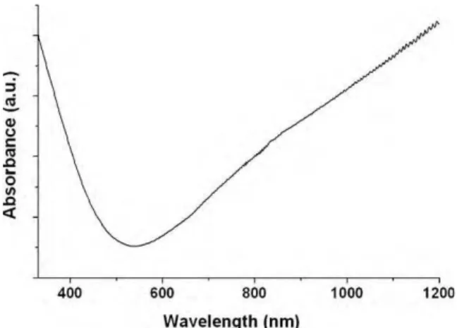
Fig. 2. UV–vis–NIR spectrum of the PEDOT nanofibers.
a sacrificial carrier polymer (PVP). After evaporation of the sol-vent during the electrospinning process, the nanofibers contained 91.7 wt% of FeTos, 2.3 wt% PVP and 6 wt% pyridine. The signifi-cantly low amount of polymer caused the fibers to be extremely sensitive to relative humidity and liquefied instantaneously upon incorporation of moisture or any organic vapor. Consequently the electrospinning was performed under a controlled dry atmosphere (typically below 10% RH). The nanofiber mats were then transferred to the vapor-phase reactor without contact with the room atmo-sphere. The polymerization was carried out under passive vacuum at room temperature for a minimum of 5 days. After polymeriza-tion, the nanofibers were rinsed with methanol in order to remove any unreacted species as well as the pyridine and PVP. Extensive structural and morphological characterization of the nanofibers is reported elsewhere[17].Fig. 1shows optical and SEM micrographs of the resulting PEDOT fibers. The fibers displayed the typical light blue color of conductive PEDOT[21,22]. Their average diameter was 350 ± 60 nm. The nanofibers were soldered at many intersections, giving a strong dimensional stability to the mat.
The UV–vis–NIR spectrum of the nanofibers displayed a low absorption in the visible region and an increasing absorption after 700 nm, extending in the near infrared. This absorption profile is characteristic of the presence of bipolarons delocalized on the
poly-Fig. 3. (a) Cyclic voltammogram of a PEDOT nanofiber mat in EMIBF4. mPEDOT= 2.0 mg, scan ratev= 5 mV s−1. (b) Charge storage capacity as a function of the scan rate.
mer backbone, demonstrating the conductive state of the polymer (cf.Fig. 2)[23,24]. The conductivity of the mat was measured with a four-point probe setup and gave an average value of 60 ± 10 S cm−1.
This is the highest value ever reported for conducting polymers
Fig. 4. Assembly of a textile supercapacitor. (a) Schematic representation of the stacked textile layers; (b) photographs of a 3 cm2all-textile flexible supercapacitor; (c) SEM image of the active materials (PEDOT nanofibers); (d) SEM image of the separator (PAN nanofibers).
POWER-13333; No. of Pages 6
4 A. Laforgue / Journal of Power Sources xxx (2010) xxx–xxx
electrospun mats. Moreover, giving that the porosity of the mats is around 80% (i.e. the material represents only 20% of the volume), and that the conductivity measurement does not take into account the porosity of the sample, the conductivity of single fibers can be estimated to be around 300 S cm−1[25].
The electrochemical properties of the nanofiber mats were investigated using cyclic voltammetry in an ionic liquid (EMIBF4).
No special precautions were taken in order to prevent contamina-tion of the medium by oxygen and water. The mats were connected at one extremity by an alligator clip, without the use of any addi-tional current collector.Fig. 3a presents a cyclic voltammogram of a PEDOT nanofiber mat.
The typical p-doping/undoping process of PEDOT can be observed, with precisely defined peaks due to the high conductiv-ity of the nanofibers. The charge storage capacconductiv-ity of the nanofibers was as high as 30 mAh g−1, and the coulombic reversibility was
over 98%. Fig. 3b presents the charge capacity as a function of cyclic voltammetry scan rate. It shows that after a slight decrease from 5 to 20 mV s−1, the charge capacity stayed relatively steady,
around 24 mAh g−1. This result demonstrates a very efficient
inser-tion/deinsertion of the ions from the electrolyte in the polymer during the doping/undoping process. It is believed that the ultra-porous nature of the active materials (∼80% porosity) is the key property that allows for this efficiency. The nanofibers average diameter being 350 nm, the maximum diffusion length of a dop-ing ion into the polymer is around 175 nm, a value by far lower than that in micro-sized particles. These electrochemical character-istics make the electrospun nanofibers good candidates for active materials in supercapacitors.
3.2. Supercapacitors assembly
All-textile supercapacitors were build by stacking layers of textile materials, as shown inFig. 4a. Carbon cloths were used as current collectors and electrospun polyacrylonitrile (PAN) nanofiber mats were used as separators (cf. Fig. 4d). PEDOT nanofibers were used as both positive and negative active mate-rials (type I device)[26]. The supercapacitor stack was embedded in a solid and flexible electrolyte made of PVDF-co-HFP and EMIBF4
(1:2). After drying of the electrolyte, the textile supercapacitors were fully flexible and no delamination of the layers was observed upon bending (cf.Fig. 4b).
3.3. Electrochemical testing
The supercapacitors were tested in ambient conditions. In a first step, the stacked layers were maintained together using Teflon
Fig. 5. Galvanostatic cycling of a PEDOT/PEDOT supercapacitor in liquid electrolyte, between 0 and 1 V. mPEDOT+= 4.34 mg; mPEDOT−= 4.0 mg; i = ±0.5 mA cm−2.
sheets and stainless steel clips, in order to test them in a liquid electrolyte (pure EMIBF4), with a three-electrode configuration.
Fig. 5 shows the galvanostatic cycling of a supercapacitor between 0 and 1 V. The positive and negative electrodes were not pre-cycled before the assembly. Because the PEDOT was partially doped during the vapor-phase polymerization, the voltage limits were ideal for a type I supercapacitor when the active material masses were matched. At 0 V, both electrodes had their open circuit potential at 0.43 V/Ref. By increasing the voltage of the device to 1 V, the potential of the positive electrode was increased to 0.96 V/Ref, and the PEDOT was then fully doped (cf. cyclic voltammogram Fig. 3a). On the other hand, at 1 V the negative electrode reached a potential of −0.04 V/Ref, corresponding to a partially undoped state
Fig. 6. (a) Galvanostatic cycling of a solid-state textile supercapacitor at 2 mA cm−2; (b) cell capacity at different current densities (according to the mass of active mate-rials); (c) cell capacity during long-term cycling. The arrow shows a cycle where bending tests were carried out during cycling.
for the PEDOT. It was imperative not to dedope further the polymer in order to keep a reasonable conductivity, as will be demonstrated later.
The perfectly linear curves obtained within these potential limits were similar to the ones obtained with electrochemical double-layer supercapacitors (EDLCs), and the pseudo-capacitive behaviors of the active materials could then be described using the usual capacitive features of EDLCs. The device had a capacity of 20 F g−1 of active materials, the positive and negative electrodes
reaching values of 75 F g−1and 85 F g−1, respectively. The
discrep-ancy between the capacities of the electrodes was reproducible on all tested devices, and illustrates the fact that it is easier to extract ions from a partially doped polymer (negative electrode case) than to insert more ions in a partially doped one (positive electrode case). The equivalent series resistance (ESR) of the cell could be measured by the ohmic drop at the beginning of discharge and was 2.2 cm−2
at 5000 Hz (the potentiostat recording one point every 200 s). In a second step, solid-state supercapacitors (as shown inFig. 4b) were tested. Fig. 6a presents a galvanostatic cycling curve of a solid-state textile supercapacitor between 0 and 1 V. The same typ-ical linear curves as in liquid electrolyte were obtained, with no decrease in the capacity (20 F g−1). The only noticeable difference
was an increase of the ESR to 20.7 cm−2 illustrating a decrease
of ion mobility within the active layers and in the solid electrolyte. Severe bending tests (more than 90◦) in both directions (left–right
and up–down) were carried out during the second cycle shown (as marked by the arrow), and no effect was observed on the cell perfor-mance. The cycling was performed at different current densities (cf. Fig. 6b) and demonstrated a perfect stability of the performances even at high current densities. This is a further evidence of the very efficient ion insertion/deinsertion in the nanostructured active materials, as observed with cyclic voltammetry (cf.Fig. 3b). The sta-bility of the cell performance upon cycling was very good, even if performed in ambient conditions: the cell capacity was still 90% of the initial capacity after 10,000 cycles (cf.Fig. 6c).
3.4. Impedance spectroscopy
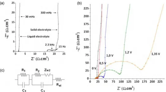
Impedance spectroscopy was used to investigate the resistance limitations within the solid-state cells.Fig. 7a presents the Nyquist plots of the supercapacitors in liquid and solid electrolytes. In
liq-uid electrolyte, the plot presents a typical curve of a pure capacitor, with no semi-circle at high frequency, indicative of very low inter-facial resistances in the system. In the solid electrolyte, we can observe a significant increase of the electrolyte resistance, repre-sented by the increase of the real part of the impedance (distance between 0 and the high frequency part of the curve on x-axis), from 1.5 to 16.4 cm−2. Moreover, two semi-circles are observed,
revealing two successive ohmic barriers (from 500 kHz to 2.3 kHz and then from 2.3 kHz to 15 Hz), followed by a capacitive behavior at low frequencies. These semi-circles are associated with different ohmic phenomena occurring in the system: the first one (at higher frequencies) is the charge transfer from the active materials to the current collector; the second one (at lower frequencies) is asso-ciated with the charge transfer at the PEDOT/electrolyte interface (i.e. the PEDOT doping/undoping process). A diffusion element is associated to the latter process due to the diffusion of the doping ions at the surface of the nanofibers. An equivalent circuit of the proposed impedance system is presented inFig. 7c. These results show that the increase in the impedance of the system in the solid electrolyte is due to a lower ion mobility within the solid electrolyte (compared to the liquid electrolyte) as well as within the active materials layer.
Fig. 7b presents the Nyquist plots of a solid-state supercapacitor at different voltages. It can be observed that the second semi-circle, related to the doping/undoping process, is significantly increased at higher voltage, due to the progressive undoping of the PEDOT on the negative electrode: at 0.5 V, the negative electrode is still in a fairly doped state and the conductivity is still high. By increasing further the voltage, the negative electrode is progressively undoped, and the polymer looses its conductivity. At a cell voltage of 1.35 V, the negative electrode is at an estimated potential of −0.2 V vs. Ag/AgCl, i.e. still not fully undoped (cf.Fig. 3a). However, its conductivity has already dropped, increasing the overall cell resistance by a factor 8. This experiment illustrates one of the limitations of the type I configuration for conducting polymer supercapacitors (same mate-rial for both electrodes): when the cell is at its maximum voltage, one of the electrodes is undoped and suffers from a lack of conduc-tivity. However, this drawback can be circumvented by designing an asymmetric supercapacitor using another type of active materi-als for the negative electrode of the supercapacitor[27], like carbon nanotubes or flexible electrospun carbon nanofibers[28].
Fig. 7. (a) Nyquist plot of the supercapacitor cell in liquid and solid electrolytes at 0 V; (b) Nyquist plots of the supercapacitor cell in solid electrolytes at different voltages. Frequency range: 10 mHz to 500 kHz, signal amplitude 10 mV. (c) Equivalent circuit associated with a supercapacitor electrode. R1and C1are the resistance and capacitance associated with the charge transfer between the current collector and the active materials; R2, C2and Zw2are the resistance, capacitance and diffusion impedance associated with the charge transfer at the active materials/electrolyte interface; Relis the resistance of the electrolyte layer.
POWER-13333; No. of Pages 6
6 A. Laforgue / Journal of Power Sources xxx (2010) xxx–xxx
4. Conclusions and perspectives
The use of electrospun PEDOT nanofiber mats as active materi-als of all-textile supercapacitors was demonstrated. The nanofiber mats were obtained by a two-step process including the elec-trospinning of oxidant containing nanofibers, followed by the vapor-phase polymerization of EDOT. The nanofibers displayed very high conductivities and flexibility. Type I supercapacitors were assembled by stacking layers of textiles with different functions (current collectors, active materials and separator) and embedded in a solid electrolyte made of EMIBF4and PVDF-co-HFP. The
elec-trochemical performances of the solid-state supercapacitors were very similar to the ones obtained in liquid electrolyte, owing to the nanostructure nature of the active materials ensuring an effective wetability by the electrolyte and a limited diffusion length of the doping ions within the polymer structure. The cells also demon-strated a high cyclability in ambient conditions and no effect of bending of the cell during its use.
However, the performances were limited by the type I config-uration, which allows the use of only half of the electrode capac-itance, and exhibits a higher cell resistance in the charged state. The use of an asymmetric configuration with the PEDOT nanofibers as the positive electrode and a flexible negative electrode made of another active material will improve the performances signifi-cantly, by allowing higher voltages to be reached as well as the use of the whole PEDOT capacitance on the positive electrode.
References
[1] Powerpaper Ltd. website,http://www.powerpaper.com/.
[2] Blue Spark Technologies website,http://www.bluesparktechnologies.com/. [3] Enfucell website,http://www.enfucell.com/.
[4] P. Hiralal, S. Imaizumi, H.E. Unalan, H. Matsumoto, M. Minagawa, M. Rouvala, A. Tanioka, G.A.J. Amaratunga, ACS Nano 4 (2010) 2730–2734.
[5] Rocket website,http://www.rocket.co.kr/. [6] Solicore website,http://www.solicore.com/.
[7] G. Dennler, S. Bereznev, D. Fichou, K. Holl, D. Ilic, R. Koeppe, M. Krebs, A. Labouret, C. Lungenschmied, A. Marchenko, Solar Energy 81 (2007) 947–957. [8] C. Meng, C. Liu, S. Fan, Electrochemistry Communications 11 (2009) 186–189. [9] M. Kaempgen, C.K. Chan, J. Ma, Y. Cui, G. Gruner, Nano Letters 9 (2009)
1872–1876.
[10] V.L. Pushparaj, M.M. Shaijumon, A. Kumar, S. Murugesan, L. Ci, R. Vajtai, R.J. Linhardt, O. Nalamasu, P.M. Ajayan, Proceedings of the National Academy of Sciences 104 (2007) 13574–13577.
[11] L. Hu, M. Pasta, F.L. Mantia, L. Cui, S. Jeong, H.D. Deshazer, J.W. Choi, S.M. Han, Y. Cui, Nano Letters 10 (2010) 708–714.
[12] Y.-Y. Horng, Y.-C. Lu, Y.-K. Hsu, C.-C. Chen, L.-C. Chen, K.-H. Chen, Journal of Power Sources 195 (2010) 4418–4422.
[13] J.-H. Sung, S.-J. Kim, S.-H. Jeong, E.-H. Kim, K.-H. Lee, Journal of Power Sources 162 (2006) 1467–1470.
[14] NEC press release 13 February 2009,http://www.nec.co.jp/press/en/0902/1302.html. [15] H. Nishide, K. Oyaizu, Science 319 (2008) 737–738.
[16] T. Suga, H. Ohshiro, S. Sugita, K. Oyaizu, H. Nishide, Advanced Materials 21 (2009) 1627–1630.
[17] A. Laforgue, L. Robitaille, Macromolecules 43 (2010) 4194–4200. [18] A. Laforgue, L. Robitaille, Chemistry of Materials 22 (2010) 2474–2480. [19] J. Fuller, A.C. Breda, R.T. Carlin, Journal of the Electrochemical Society 144 (1997)
L67–L70.
[20] J. Fuller, A.C. Breda, R.T. Carlin, Journal of Electroanalytical Chemistry 459 (1998) 29–34.
[21] C. Kvarnström, H. Neugebauer, S. Blomquist, H.J. Ahonen, J. Kankare, A. Ivaska, N.S. Sariciftci, Synthetic Metals 101 (1999) 66.
[22] Q. Pei, G. Zuccarello, M. Ahlskog, O. Inganäs, Polymer 35 (1994) 1347–1351. [23] H. Neugebauer, Journal of Electroanalytical Chemistry 563 (2004) 153–159. [24] S. Kim, I. Pang, J. Lee, Macromolecular Rapid Communications 28 (2007)
1574–1580.
[25] A. Laforgue, L. Robitaille, Synthetic Metals 158 (2008) 577–584.
[26] A. Rudge, J. Davey, I. Raistrick, S. Gottesfeld, J.P. Ferraris, Journal of Power Sources 47 (1994) 89–107.
[27] A. Laforgue, P. Simon, J.F. Fauvarque, J.F. Sarrau, P. Lailler, Journal of the Elec-trochemical Society 148 (2001) A1130–A1134.
[28] S. Imaizumi, H. Matsumoto, K. Suzuki, M. Minagawa, M. Kimura, A. Tanioka, Polymer Journal 41 (2009) 1124–1128.