Publisher’s version / Version de l'éditeur:
Applied Physics Letters, 89, 18, pp. 183506-1-183506-3, 2006-10-01
READ THESE TERMS AND CONDITIONS CAREFULLY BEFORE USING THIS WEBSITE. https://nrc-publications.canada.ca/eng/copyright
Vous avez des questions? Nous pouvons vous aider. Pour communiquer directement avec un auteur, consultez la
première page de la revue dans laquelle son article a été publié afin de trouver ses coordonnées. Si vous n’arrivez pas à les repérer, communiquez avec nous à [email protected].
Questions? Contact the NRC Publications Archive team at
[email protected]. If you wish to email the authors directly, please see the first page of the publication for their contact information.
NRC Publications Archive
Archives des publications du CNRC
This publication could be one of several versions: author’s original, accepted manuscript or the publisher’s version. / La version de cette publication peut être l’une des suivantes : la version prépublication de l’auteur, la version acceptée du manuscrit ou la version de l’éditeur.
For the publisher’s version, please access the DOI link below./ Pour consulter la version de l’éditeur, utilisez le lien DOI ci-dessous.
https://doi.org/10.1063/1.2374684
Access and use of this website and the material on it are subject to the Terms and Conditions set forth at
High temperature integrated ultrasonic shear wave probes
Jen, C.-K.; Ono, Y.; Kobayashi, M.
https://publications-cnrc.canada.ca/fra/droits
L’accès à ce site Web et l’utilisation de son contenu sont assujettis aux conditions présentées dans le site LISEZ CES CONDITIONS ATTENTIVEMENT AVANT D’UTILISER CE SITE WEB.
NRC Publications Record / Notice d'Archives des publications de CNRC:
https://nrc-publications.canada.ca/eng/view/object/?id=f635b47b-a1a1-4a48-b622-b77e5b1e99bd https://publications-cnrc.canada.ca/fra/voir/objet/?id=f635b47b-a1a1-4a48-b622-b77e5b1e99bdHigh temperature integrated ultrasonic shear wave probes
C.-K. Jen,a兲Y. Ono, and M. Kobayashi
Industrial Materials Institute, National Research Council of Canada, 75 Blvd. de Mortagne, Boucherville, Quebec J4B 6Y4, Canada
共Received 12 June 2006; accepted 16 September 2006; published online 31 October 2006兲 Integrated ultrasonic shear wave probes have been fabricated using steel substrates through a paint-on method with the use of mode conversion from longitudinal to shear waves. The probe can be operated up to 150 ° C. A probe simultaneously generating and receiving both longitudinal and shear waves is also demonstrated. © 2006 American Institute of Physics.关DOI:10.1063/1.2374684兴
Due to the simplicity, speed, economy, and capability to probe the interior of an opaque material, the ultrasonic tech-niques are often used to perform nondestructive testing and characterization共NDT&C兲 of materials.1Many NDT&Cs are also mandatory to be performed at elevated temperatures, thus high temperature共HT兲 ultrasonic transducers 共UTs兲 are in demand. In addition, ultrasonic techniques prefer and sometimes require UTs of large bandwidth and high effi-ciency. Various efforts have been devoted to the development of such piezoelectric HTUTs 共Refs. 2–5兲 and they may be supplied by several companies. However, the reported efforts have so far devoted to longitudinal共L兲 wave UTs only. It is understood that shear共S兲 waves may be advantageous over L waves for NDT&C of materials because liquid and gas me-dium do not support S waves. For instance, the higher sen-sitivity to detect cracks or gaps filled with liquids could be expected using S waves than L waves in a pulse-echo tech-nique since reflection coefficients of S waves at solid/liquid interfaces are unity, namely, total reflection, while those of L waves are less than unity.6 In addition, S waves have better spatial resolution than L waves to detect small defects such as cracks and inclusions in products and materials due to shorter wavelength of S waves as compared to that of L waves at the same frequency.6
For the evaluation of material properties, sometimes it is important to measure shear modulus and viscoelastic proper-ties in which S wave properproper-ties are a requisite. Furthermore, a UT setup to generate and receive both L and S waves at the same sensor location would also be of interest because engi-neering constants such as Young’s modulus require measure-ment of both S and L waves. In the past special crystal cut, for example, 10° rotated Y-cut lithium niobate and tilted c-axis zinc oxide thin films were reported to generate and receive both L and S waves simultaneously.7 In this study, methods are presented to achieve HT integrated ultrasonic S wave transducers and also provide a means to excite and receive both L and S waves at elevated temperatures.
The mode conversion from L to S wave due to reflection at a solid-air interface was reported.8,9 It means that the L wave UT together with L-S mode conversion caused by the reflection at a solid-air interface can be effectively used as a Swave probe as shown in Fig.1. In Fig.1, Liwaves
gener-ated by a L wave UT reach a solid-air interface and reflected as Lr and Sr waves. The equations governing the reflection
and mode conversion with respect to the L wave incident
anglecan be given in Eqs.共1兲–共3兲,10where Vland Vsare L
and S wave velocities in the solid, respectively, and Rlland
Rsl are energy reflection coefficients of the L and S waves, respectively. Vl sin = Vs sin, 共1兲 Rll=
冋
cos22−共Vs/Vl兲2sin 2sin 2
cos22+共V
s/Vl兲2sin 2sin 2
册
2
, 共2兲
Rsl=
4共Vs/Vl兲2cos22sin 2cos 2
关cos2
2+共Vs/Vl兲2sin 2sin 2兴2
. 共3兲
In this study, a mild steel with the L wave velocity Vl
= 5900 m / s and S wave velocity Vs= 3200 m / s was used as
the substrate. Figure2shows the calculated energy reflection coefficient based on Eqs.共2兲and共3兲 for the mild steel sub-strate. It indicates that the maximum energy conversion rate from the Liwave to the Srwave is 97.5% at= 67.2°, and the
reduction of the energy conversion rate is within 1% in the range between 60.8° and 72.9°.
We have developed integrated L wave thick film 共⬎40m兲 HTUTs.4 Thick ceramic films as piezoelectric UTs were successfully deposited on metallic and nonmetallic substrates by a spray technique. In the film fabrication, a composite consisting of piezoelectric powders such as lead zirconate titanate 共PZT兲 well mixed with solution such as PZT of high dielectric constant is directly sprayed onto the substrate. It is then dried and fired. Multiple coating is used to achieve preferable thickness which is related to the oper-ating ultrasonic frequency. A corona poling technique is used to achieve the piezoelectricity of the film and the top elec-trode is accomplished by painting a silver paste. The attrac-tive characteristics of these L UTs are that they共a兲 can be
a兲Author to whom correspondence should be addressed; electronic mail: [email protected]
FIG. 1. Reflection and mode conversion with an incidence of L wave at a solid-air interface.
APPLIED PHYSICS LETTERS 89, 183506共2006兲
0003-6951/2006/89共18兲/183506/3/$23.00 89, 183506-1 © 2006 American Institute of Physics
integrated onto the desired planar or curved substrate at the desired NDT&C site with handheld equipments and under possible lowest temperature without a furnace, 共b兲 do not need a couplant,共c兲 can operate in pulse-echo and transmis-sion modes with a signal to noise ratio 共SNR兲 better than 30 dB between 5 and 10 MHz,共d兲 can operate from −100 up to more than 400 ° C, and共e兲 can be operated with an array configuration. Typically, the measured d33of this PZT
com-posite film is about 30⫻ 10−12m / V, the Kt about 0.2, the
relative dielectric constant 320, the density 4400 kg/ m3, and
the L wave velocity about 2200 m / s. Such integrated L wave HTUTs together with the above mentioned characteristics are used to achieve our HT integrated S wave probe presented here.
Our approach considers a simple way to fabricate the L wave UT and lets the L UT be in a plane parallel to the mode converted S wave direction as shown in Fig.3共a兲. This ap-proach could reduce the machining time of the substrate and thick UT film fabrication difficulty. By considering this cri-terion, the+ needs to be 90°. From Eq. 共1兲, Snell’s law, we can obtain= 61.5°. At this angle, the conversion rate is 96.7% that is only 0.8% smaller than the maximum conver-sion rate at 67.2°, based on the result in Fig.2. Therefore, Figs. 3共a兲 and 3共b兲 show the design schematic and actual device developed for this study, respectively. Figures 4共a兲
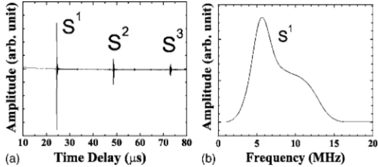
and 4共b兲 show the ultrasonic signal in time and frequency domains, respectively, of the received Srwave in the
pulse-echo mode at 150 ° C. The Snrepresents the nth round-trip of
the S wave echoes traversing back and forth between the L UT and the probing end in Fig.3. The center frequency of the S1 echo was 5.7 MHz and the 6 dB bandwidth was 4.0 MHz. The SNR of S1echo was about 30 dB. The SNR is defined as the ratio of the amplitude of the S1echo over that
of the undesired signals between the Sn echoes in Fig.4共a兲.
The signal strength of the S1 echo at 150 ° C was 5 dB smaller than that at room temperature. It can be seen that the received L wave is not visible due to the fact that the dimen-sion of the substrate has been chosen so that the reflected L wave from the probing end does not enter into the aperture of the L UT. The same design scheme has also been applied onto an aluminum substrate. Ultrasonic measurement results at 150 ° C with good SNR have been obtained with the alu-minum substrate as well.
If one would like to generate and receive both L and S waves at the same time, then the S wave probe shown in Fig.
3can be modified to achieve such a purpose. In fact, it sim-ply makes a slanted surface with an angle of 45° from the intersection of the slanted plane and the line from the center of the L UT as shown in Fig.5共a兲. The 45° angle plane will reflect the energy of the Liwave into the Lr,45°wave normal
to the probing end as shown in Fig.5共a兲. Therefore, in prin-ciple, the upper part of the L wave, generated from L UT, can be used to produce the Srwave and the lower part to produce
the Lr,45° wave. Figure 5共b兲 shows an actual device
devel-oped. Figure6shows ultrasonic signal in time domain in the pulse-echo mode at 150 ° C, in which the Sr共S1兲 and Lr共L1兲
waves are observed simultaneously. The L1 represents the
first round-trip L wave echo traversing between the L UT and the probing end. The center frequencies of the S1 and L1 echoes were 6.2 and 7.3 MHz and the 6 dB bandwidths were 4.0 and 5.9 MHz, respectively. As expected, there was no difference in frequency spectra of converted S waves in Figs.
4共a兲 and6. During the top electrode fabrication for the de-vice shown in Fig. 5共b兲, the area of the top electrode was adjusted so that the amplitudes of the reflected Sr and Lr,45°
waves were nearly the same. The SNR of the L1and S1 was
about 20 dB. A similar approach was also applied onto an aluminum substrate and ultrasonic measurement results at 150 ° C with good SNR were also obtained.
In conclusion, integrated ultrasonic S wave probes were fabricated onto steel substrates through a paint-on method
FIG. 2. Energy reflection coefficient vs incident angle.
FIG. 3.共Color online兲 Schematic diagram and 共b兲 actual device of an inte-grated S wave probe with the L wave UT located in a plane parallel to the direction of mode converted S wave where= 61.5°.
FIG. 4. Ultrasonic signal in共a兲 time and 共b兲 frequency domains of the S wave probe shown in Fig.3共b兲at 150 ° C.
FIG. 5.共Color online兲 Schematic diagram and 共b兲 actual device of an inte-grated L and S wave probe with the L wave UT located in a plane parallel to the direction of mode converted S wave.
183506-2 Jen, Ono, and Kobayashi Appl. Phys. Lett. 89, 183506 共2006兲
with the use of mode conversion from L to S waves. The theoretical calculation indicates that the maximum energy conversion rate from the L to S wave is 97.5% at the L wave incident angle= 67.2° as shown in Fig.2, and the reduction of the energy conversion rate is within 1% in the range between 60.8° and 72.9°. A novel approach was taken to fabricate the L wave UT and let the L UT be in a plane parallel to the propagation direction of the mode converted S waves as shown in Fig.3. By considering this criterion, the is 61.5° and the reduction of energy conversion rate at this angle is only 0.8% smaller than the maximum conversion
rate at= 67.2°. This approach could reduce the machining time of the substrate and thick UT film fabrication difficulty. A probe that can simultaneously generate and receive both L and S waves was also demonstrated. All the above mentioned probes have been made and operated up to 150 ° C with a center frequency of 5 – 7 MHz, 6 dB bandwidth of 4 – 6 MHz, and SNR of more than 20 dB. Similar results have been obtained for ultrasonic probes with aluminum sub-strates. It is noted that the UT can operate up to more than 400 ° C when bismuth titanate powders instead of PZT pow-ders are used.4,5
1
J. Krautkrämer and H. H. Krautkrämer, Ultrasonic Testing of Materials, 4th edition共Springer, Berlin, 1990兲, pp. 528–550.
2
T. Arakawa, K. Yoshikawa, S. Chiba, K. Muto, and Y. Atsuta, Nondestr. Test. Eval. 7, 263共1992兲.
3
K. J. Kirk, A. McNab, A. Cochran, I. Hall, and G. Hayward, IEEE Trans. Ultrason. Ferroelectr. Freq. Control 46, 311共1999兲.
4
M. Kobayashi and C.-K. Jen, Smart Mater. Struct. 13, 951共2004兲. 5
R. Kazys, A. Voleisis, R. Sliteris, L. Mazeika, R. V. Nieuwenhove, P. Kupschus, and H. A. Abderrahim, IEEE Trans. Ultrason. Ferroelectr. Freq. Control 52, 525共2005兲.
6
H. Kuttruff, Ultrasonics: Fundamentals and Applications 共Elsevier Applied Science, London, 1991兲, pp. 277–279.
7
C.-K. Jen, K. Sreenivas, and M. Sayer, J. Acoust. Soc. Am. 84, 26共1988兲. 8
B. A. Auld, Acoustic Fields and Waves in Solids共Wiley, New York, 1973兲, Vol. 2, pp. 30–38.
9
M. O. Si-Chaib, H. Djelouah, and M. Bocquet, NDT & E Int. 33, 91 共2000兲.
10
W. G. Mayer, Ultrasonics 3, 62共1965兲. FIG. 6. Ultrasonic signal at 150 ° C obtained with the L and S wave probe in
Fig.5共b兲.
183506-3 Jen, Ono, and Kobayashi Appl. Phys. Lett. 89, 183506 共2006兲